Poor grounding through cable glands causes 30% of industrial electrical failures, leading to equipment damage, fires, and safety hazards. Proper grounding techniques can prevent these costly disasters.
Proper grounding via cable glands requires continuous electrical path from cable armor to equipment ground, impedance below 1 ohm for effective fault current flow, corrosion-resistant connections, proper EMC shielding continuity, and compliance with electrical codes (NEC1, IEC) for personnel safety and equipment protection.
Last week, David called me after a devastating incident at his chemical plant. A lightning strike caused €500,000 in equipment damage because their cable gland grounding system failed to provide adequate protection. The investigation revealed multiple grounding deficiencies that could have been prevented with proper design and installation.
目錄
- Why Is Proper Grounding Through Cable Glands Critical for Safety?
- What Are the Essential Components of an Effective Cable Gland Grounding System?
- How Do You Design and Install Grounding Systems for Different Applications?
- What Are Common Grounding Mistakes and How Can You Avoid Them?
Why Is Proper Grounding Through Cable Glands Critical for Safety?
Grounding through cable glands serves multiple critical safety functions that protect both personnel and equipment from electrical hazards. Understanding these functions is essential for proper system design.
Proper grounding provides fault current return path for protective device operation, limits touch voltages during ground faults, dissipates static electricity buildup, provides EMC shielding continuity, protects against lightning and surge damage, and ensures compliance with electrical safety codes and standards.
Fault Current Protection
Ground Fault Current Path:
- Low impedance path: Enables protective devices to operate quickly
- Fault current magnitude: Must be sufficient to trip circuit breakers
- Clearing time: Reduces arc flash energy and equipment damage
- Personnel protection: Limits step and touch voltages
Impedance Requirements:
- NEC requirement: Effective ground fault current path
- IEEE 142 guidance: Ground resistance typically <1 ohm
- IEC 61936: Specific requirements for different voltage levels
- Testing verification: Regular impedance measurements required
Hassan recently told me: “Chuck, your grounding analysis revealed our fault current path had 15 ohms impedance. We never would have cleared a ground fault safely.”
Lightning and Surge Protection
Lightning Strike Scenarios:
- Direct strikes: Cable armor provides conduction path
- Induced surges: Grounding limits voltage buildup
- Ground potential rise2: Proper bonding prevents flashover
- 設備保護: Surge protective devices require good grounding
Surge Current Handling:
- Peak current capacity: 10kA to 200kA depending on application
- Energy dissipation: Heat generation and thermal effects
- Multiple discharge paths: Parallel grounding conductors
- Coordination: With surge protective devices
EMC and Shielding Continuity
Electromagnetic Compatibility:
- 遮罩連續性: 360-degree connection around cable
- 傳輸阻抗3: Low impedance at high frequencies
- Common mode currents: Proper return path prevents radiation
- Noise reduction: Effective shielding reduces interference
屏蔽效能:
- 頻率響應: Effectiveness varies with frequency
- 連接品質: Crimped connections preferred over clamps
- Cable armor types: Braid, tape, or wire armor considerations
- Termination methods: Proper shield termination techniques
Static Electricity Dissipation
Static Buildup Prevention:
- Charge accumulation: On non-conductive surfaces
- Dissipation path: Through grounding system
- Ignition prevention: In explosive atmospheres
- Personnel protection: Prevents shock hazards
Dissipation Requirements:
- Resistance range: 10⁶ to 10⁹ ohms for static dissipation
- Continuous path: From source to ground reference
- 環境因素: Humidity and contamination effects
- 監控系統: Static charge level measurement
At Bepto, we design our cable glands with integrated grounding features that ensure reliable electrical continuity and compliance with all relevant safety standards. 😉
What Are the Essential Components of an Effective Cable Gland Grounding System?
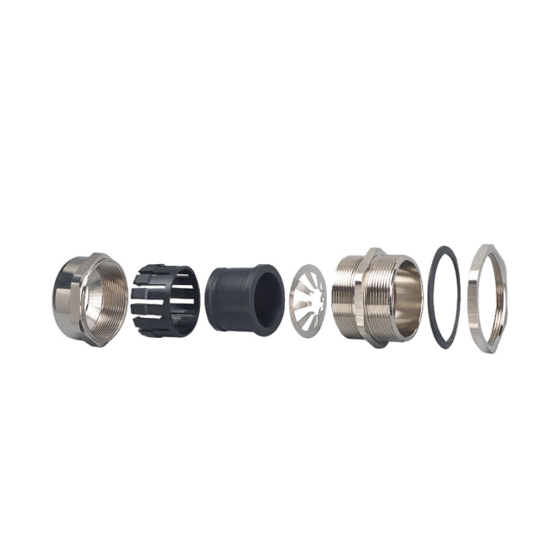
An effective grounding system requires multiple components working together to provide reliable electrical continuity and safety protection. Each component has specific requirements and functions.
Essential grounding components include cable armor termination hardware, grounding bushings or lugs, bonding conductors, ground bars or busbars, grounding electrodes, and testing points for verification, all designed to provide continuous low-impedance path to earth ground.
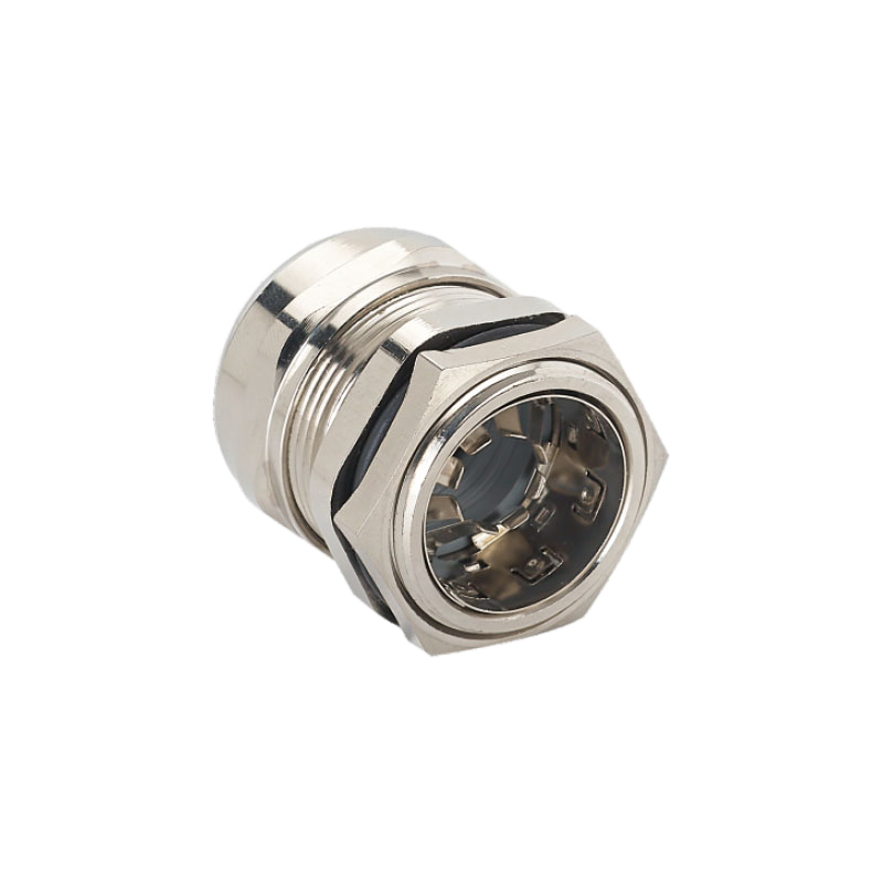
Cable Armor Termination
Armor Termination Methods:
- Compression glands: Direct mechanical connection to armor
- Barrier glands: Separate armor and conductor termination
- Explosion-proof glands: Threaded engagement with armor
- EMC glands: 360-degree shield termination
Connection Requirements:
- 機械完整性: Withstand cable pulling forces
- 電氣連續性: Low resistance connection
- 耐腐蝕性: Long-term reliability
- 環境保護: Seal against moisture ingress
Grounding Hardware
Grounding Bushing Design:
- 材質: Bronze, brass, or stainless steel
- 線程交戰: Minimum 5 full threads
- Grounding lug: Integral or separate attachment
- 密封: O-ring or gasket seal
Ground Lug Specifications:
- Current capacity: Based on fault current calculations
- Wire range: Accommodate specified conductor sizes
- 扭力要求: Proper connection without damage
- Marking: Clear identification of grounding point
David shared: “Your grounding hardware selection eliminated the corrosion problems we had with our previous system. The connections are still perfect after three years.”
Bonding Conductors
Conductor Sizing:
- NEC Table 250.122: Equipment grounding conductor sizing
- Fault current capacity: Based on protective device ratings
- Voltage drop: Minimize impedance for effective operation
- Mechanical protection: Prevent damage during installation
安裝需求:
- Routing: Direct path to grounding point
- Support: Proper mechanical support
- 保護: Against physical damage
- 無障礙: For inspection and testing
Grounding Electrode Systems
Electrode Types:
- Ground rods: Driven electrodes for general applications
- Ground plates: Buried plates for high current applications
- Concrete-encased electrodes: Ufer grounds4 in foundations
- Ground rings: Perimeter grounding for large facilities
System Design:
- Resistance targets: Typically 5-25 ohms depending on application
- Soil resistivity: Testing required for proper design
- Corrosion protection: Appropriate materials for soil conditions
- Interconnection: Multiple electrodes bonded together
Testing and Verification Points
Test Point Requirements:
- 無障礙: Easy access for routine testing
- 識別: Clear marking of test points
- 保護: Weather-resistant enclosures
- 文件: Test point locations and procedures
測試方法:
- 電阻測量: Ground resistance testing
- 連續性測試: Path verification
- Impedance testing: AC impedance measurement
- 熱成像: Connection quality assessment
How Do You Design and Install Grounding Systems for Different Applications?
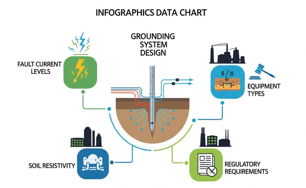
Different applications have unique grounding requirements based on voltage levels, environmental conditions, and safety considerations. Proper design ensures effective protection for each specific application.
Grounding system design requires analysis of fault current levels, environmental conditions, soil resistivity, equipment types, and regulatory requirements to determine electrode configuration, conductor sizing, connection methods, and testing procedures for optimal safety and performance.
Low Voltage Applications (≤1000V)
Residential and Commercial:
- Service entrance: Main grounding electrode conductor
- Equipment grounding: Branch circuit protection
- GFCI protection: Personnel safety in wet locations
- Surge protection: Whole-house surge protective devices
工業設施:
- Equipment grounding: Motor and machinery protection
- 控制系統: Instrumentation and control grounding
- 緊急系統: Backup power grounding
- 製程設備: Chemical and manufacturing applications
Medium Voltage Applications (1kV-35kV)
Distribution Systems:
- Transformer grounding: Neutral and case grounding
- Switchgear grounding: Metal-clad equipment
- Cable systems: Sheath and armor grounding
- Protective relaying: Ground fault detection
設計考量:
- Ground fault current: Higher magnitude fault currents
- Touch and step voltages: Personnel safety calculations
- Ground potential rise: System performance during faults
- Coordination: With protective devices and systems
Hassan told me: “Your medium voltage grounding design prevented a major incident when we had a cable fault. The system performed exactly as designed.”
High Voltage Applications (>35kV)
Transmission Systems:
- Substation grounding: Comprehensive grounding grids
- Tower grounding: Transmission line structures
- Cable systems: High voltage cable installations
- Equipment grounding: Transformers and switchgear
Special Requirements:
- IEEE 80 compliance: Substation grounding design
- Soil resistivity modeling: Computer analysis required
- Safety calculations: Touch and step voltage limits
- 季節性變化: Soil moisture effects
Hazardous Location Applications
Explosive Atmospheres:
- 本質安全: Special grounding requirements
- 防爆: Enclosure grounding integrity
- 靜電消散: Prevent ignition sources
- Bonding requirements: Metallic equipment interconnection
Special Considerations:
- API RP 2003: Petroleum industry grounding
- NFPA 77: Static electricity protection
- IEC 60079: International explosive atmosphere standards
- 文件: Detailed grounding drawings and procedures
海洋與離岸應用
Shipboard Systems:
- Hull grounding: Ship’s structure as ground reference
- 隔離: From shore ground when in port
- 陰極保護: Corrosion prevention systems
- 安全系統: Emergency equipment grounding
離岸平台:
- Structure grounding: Platform steel as ground reference
- Seawater grounding: Natural electrode system
- Lightning protection: Comprehensive protection systems
- Helicopter decks: Special grounding requirements
David recently shared: “Your offshore grounding expertise helped us design a system that’s performed flawlessly for five years in harsh North Sea conditions.”
安裝最佳實務
Cable Gland Installation:
- 扭力規格: Proper tightening without damage
- 複合線: Conductive compounds where required
- 密封完整性: Maintain environmental protection
- 接地驗證: Test continuity after installation
Connection Methods:
- Compression connections: Preferred for permanent installations
- Welded connections: High current applications
- Bolted connections: Accessible for maintenance
- 防腐蝕: Appropriate materials and coatings
測試與試運轉
Initial Testing:
- 連續性驗證: All grounding paths
- 電阻測量: Ground electrode systems
- Impedance testing: Fault current paths
- 絕緣測試: Verify proper isolation
持續維護:
- Annual testing: Ground resistance measurements
- 目視檢查: Connection condition assessment
- 熱成像:熱點識別
- 文件: Test results and trending
At Bepto, we provide comprehensive grounding design support and testing guidance to ensure your cable gland grounding systems meet all safety and performance requirements. 😉
What Are Common Grounding Mistakes and How Can You Avoid Them?
Grounding mistakes can have catastrophic consequences, from equipment damage to personnel injury. Understanding common errors helps prevent these dangerous situations.
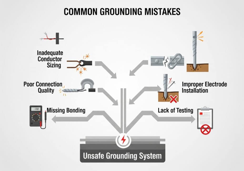
Common grounding mistakes include inadequate conductor sizing, poor connection quality, missing bonding between systems, improper electrode installation, lack of testing and maintenance, and failure to consider environmental factors, all leading to ineffective fault protection and safety hazards.
Design Phase Mistakes
Inadequate System Analysis:
- 故障電流計算: Underestimating available fault current
- Impedance analysis: Not considering total circuit impedance
- Voltage drop: Ignoring grounding conductor voltage drop
- 未來擴展: Not planning for system growth
Improper Conductor Sizing:
- Table 250.122 misapplication: Using minimum sizes inappropriately
- Fault current capacity: Inadequate for available fault current
- Parallel paths: Not considering multiple grounding paths
- Length considerations: Voltage drop over long distances
Hassan shared: “We discovered our grounding conductors were undersized by 50% when we did a proper fault current analysis. Your guidance prevented a potential disaster.”
Installation Mistakes
Poor Connection Quality:
- 連接鬆脫: High resistance and heating
- Dissimilar metals: 電偶腐蝕5 issues
- 扭力不足: Connections loosening over time
- Missing hardware: Washers, lock washers, or thread compound
Improper Cable Gland Installation:
- Insufficient thread engagement: Mechanical and electrical failure
- 過度緊固: Damage to threads or seals
- Wrong gland type: Inappropriate for cable armor type
- Missing grounding hardware: No electrical continuity
環境考量
Corrosion Problems:
- 材料選擇: Inappropriate for environment
- 電鍍相容性: Dissimilar metal connections
- 防護塗層: Missing or inadequate protection
- 排水: Water accumulation at connections
Soil Conditions:
- Resistivity variations: Seasonal and moisture effects
- Chemical contamination: Accelerated corrosion
- 物理保護: Damage from excavation or settling
- Electrode depth: Insufficient for stable resistance
David told me: “Your environmental analysis revealed why our ground resistance was varying by 300%. The seasonal moisture changes were dramatic.”
Testing and Maintenance Failures
測試不足:
- Initial verification: Not testing after installation
- Periodic testing: Missing routine maintenance testing
- Test methods: Using inappropriate test equipment
- 文件: Poor record keeping and trending
疏於維護:
- 目視檢查: Not identifying obvious problems
- 連接維護: Allowing corrosion buildup
- System modifications: Not updating grounding after changes
- 訓練: Inadequate personnel training
Code Compliance Issues
NEC Violations:
- Article 250: Grounding and bonding requirements
- Equipment grounding: Missing or inadequate conductors
- Bonding requirements: Not bonding metallic systems
- GFCI protection: Missing where required
Local Code Issues:
- Amendments: Local modifications to national codes
- 檢查要求: Special testing or documentation
- Permit requirements: Installation and modification permits
- Utility requirements: Coordination with utility grounding
預防策略
Design Review Process:
- Independent review: Third-party design verification
- 遵守法規: Systematic code review
- Calculation verification: Independent fault current analysis
- Future considerations: Planning for modifications and expansion
Quality Installation:
- 合格人員: Properly trained installers
- Inspection procedures: Step-by-step verification
- 測試協議: Comprehensive commissioning tests
- 文件: Complete as-built drawings and test records
持續維護:
- Routine inspection: Regular visual and thermal inspection
- Periodic testing: Annual or bi-annual testing programs
- 趨勢分析: Identifying degradation patterns
- Corrective action: Prompt repair of identified problems
Hassan recently said: “Implementing your prevention strategies transformed our grounding reliability. We haven’t had a grounding-related failure in two years.”
Bepto’s Grounding Support Services
We provide comprehensive grounding support to prevent common mistakes:
- Design review services: Independent verification of grounding designs
- 安裝訓練: Proper techniques and procedures
- Testing support: Equipment and procedure recommendations
- Maintenance programs: Ongoing support and trending analysis
- 緊急應變: Rapid support for grounding failures
Case Study: Preventing Catastrophic Failure
Situation: Chemical processing plant with recurring equipment failures
問題: Inadequate grounding causing protective device misoperation
解決方案: Complete grounding system redesign and upgrade
結果: Zero grounding-related failures over three years
節約: €2.3 million in prevented downtime and equipment damage
David shared: “The investment in proper grounding design and Bepto’s support has paid for itself many times over. Our system reliability is now industry-leading.”
總結
Proper grounding through cable glands requires systematic design, quality installation, and ongoing maintenance to provide effective fault protection and prevent catastrophic failures.
FAQs About Cable Gland Grounding
Q: What’s the difference between grounding and bonding in cable gland applications?
A: Grounding connects equipment to earth ground for fault protection, while bonding connects metallic parts together to eliminate potential differences. Cable glands typically require both – bonding to connect cable armor to equipment, and grounding to connect the equipment to earth ground.
Q: How do I determine the proper size for grounding conductors through cable glands?
A: Grounding conductor sizing follows NEC Table 250.122 based on the rating of the overcurrent protective device. However, you must also verify the conductor can handle available fault current without damage. At Bepto, we provide sizing calculations for your specific applications.
Q: Can I use aluminum grounding conductors with cable glands?
A: Aluminum conductors can be used if properly connected with appropriate hardware designed for aluminum. However, copper is preferred for grounding applications due to better corrosion resistance and lower resistance. Always check local codes for specific requirements.
Q: How often should I test cable gland grounding systems?
A: Testing frequency depends on the application and environment. Generally, annual testing is recommended for critical systems, with visual inspections every six months. High-corrosion environments may require more frequent testing. We provide specific recommendations based on your conditions.
Q: What should I do if I find high resistance in my cable gland grounding system?
A: High resistance indicates a problem that must be corrected immediately. Common causes include loose connections, corrosion, or damaged conductors. The system should be taken out of service until repairs are completed and proper resistance is verified through testing.
-
Access the official source for the National Electrical Code (NEC) to understand its comprehensive safety standards. ↩
-
Learn the technical details of Ground Potential Rise (GPR) and its implications for electrical system safety. ↩
-
Dive into the concept of transfer impedance and its critical role in measuring cable shield effectiveness. ↩
-
Explore the design and application of Ufer grounds (concrete-encased electrodes) as an effective grounding method. ↩
-
Understand the electrochemical process of galvanic corrosion that occurs when dissimilar metals are in contact. ↩
