
Solar installers are losing thousands of dollars annually due to undetected voltage drop issues that reduce system efficiency by 3-8%, create dangerous hot spots exceeding 85°C at high-resistance connections, cause premature inverter shutdowns and equipment failures, generate costly warranty claims and customer complaints, and violate electrical code requirements for maximum allowable voltage drop limits. The complexity of voltage drop calculations across multiple string configurations, varying cable lengths, diverse connector types, and changing environmental conditions creates confusion among installers who often overlook the critical impact of connector resistance, leading to underperforming systems, safety hazards, and reduced profitability that can devastate solar installation businesses.
Voltage drop in solar arrays is calculated using Ohm’s Law1 (V = I × R) where total resistance includes cable resistance plus connector resistance, with quality connectors contributing less than 0.1% voltage drop while poor connectors can cause 1-3% losses. Proper calculation requires analyzing string current, cable length and gauge, connector specifications, and temperature effects to ensure total voltage drop remains below 3% per NEC requirements for optimal system performance and code compliance.
Last week, I received an emergency call from Jennifer Martinez, lead electrician at a major solar EPC company in Phoenix, Arizona, who discovered that cheap MC4 connectors on a 1.5MW commercial project were causing 4.2% voltage drop and creating hot spots over 95°C, threatening system shutdown and voiding performance warranties. After replacing all connections with our premium low-resistance connectors and recalculating the voltage drop, Jennifer’s team achieved 98.7% system efficiency and eliminated all thermal issues, saving the project $180,000 in potential losses! ⚡
Obsah
- What Is Voltage Drop and Why Does It Matter in Solar Arrays?
- How Do You Calculate Voltage Drop in Solar String Configurations?
- What Is the Impact of Connector Resistance on System Performance?
- How Do You Minimize Voltage Drop Through Proper Design and Component Selection?
- What Are the Code Requirements and Best Practices for Voltage Drop Management?
- FAQs About Solar Array Voltage Drop
What Is Voltage Drop and Why Does It Matter in Solar Arrays?
Understanding voltage drop fundamentals is essential for designing efficient and code-compliant solar photovoltaic systems.
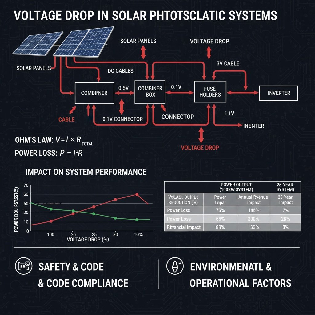
Voltage drop in solar arrays is the reduction in electrical potential that occurs when current flows through resistance in cables, connectors, and other system components, resulting in lower voltage delivered to inverters and reduced power output. This phenomenon follows Ohm’s Law where voltage drop equals current multiplied by total circuit resistance, including DC cable resistance, connector contact resistance, fuse holder resistance, and combiner box internal resistance. Excessive voltage drop reduces system efficiency, creates thermal stress on components, violates electrical code requirements, and can cause inverter shutdown or malfunction.
Physical Principles of Voltage Drop
Ohm’s Law Application: Voltage drop (V) equals current (I) multiplied by resistance (R), where resistance includes all series components in the current path.
Power Loss Relationship: Power loss due to voltage drop equals I²R, meaning losses increase exponentially with current and linearly with resistance.
Vplyv teploty: Conductor resistance increases with temperature, typically 0.4% per degree Celsius for copper, affecting voltage drop calculations.
Current Distribution: In parallel string configurations, unequal voltage drops can cause current imbalances and reduced overall system performance.
Vplyv na výkon systému
Power Output Reduction: Each 1% voltage drop typically reduces system power output by approximately 1%, directly affecting energy production and revenue.
Inverter Efficiency: Reduced DC voltage can push inverters outside optimal operating ranges, further reducing conversion efficiency.
Maximum Power Point Tracking2: Voltage drop affects MPPT algorithms, potentially causing inverters to operate at suboptimal power points.
System Monitoring: Voltage drop can mask actual panel performance issues and complicate system troubleshooting.
Economic Consequences
| Voltage Drop Level | Power Loss | Annual Revenue Impact (100kW System) | 25-Year Financial Impact |
|---|---|---|---|
| 1% | 1kW | $150-300 | $3,750-7,500 |
| 2% | 2kW | $300-600 | $7,500-15,000 |
| 3% | 3kW | $450-900 | $11,250-22,500 |
| 5% | 5kW | $750-1,500 | $18,750-37,500 |
Safety and Code Compliance Issues
Thermal Effects: High resistance connections create heat, potentially causing fires or equipment damage.
Arc Fault Risk: Poor connections with high resistance are more prone to arcing and electrical faults.
Code Violations: NEC Article 690 limits voltage drop to 3% for optimal system performance and safety.
Insurance Implications: Non-compliant installations may void insurance coverage and create liability issues.
Environmental and Operational Factors
Kolísanie teploty: Daily and seasonal temperature changes affect conductor resistance and voltage drop calculations.
Účinky starnutia: Component resistance typically increases over time due to corrosion, mechanical stress, and material degradation.
Požiadavky na údržbu: High-resistance connections require more frequent inspection and maintenance to prevent failures.
System Reliability: Excessive voltage drop reduces overall system reliability and increases maintenance costs.
Working with David Thompson, senior project manager at a leading solar developer in Denver, Colorado, I learned that proper voltage drop analysis during design phase can identify potential issues before installation, saving 15-20% on total project costs through optimized cable sizing and connector selection! 📊
How Do You Calculate Voltage Drop in Solar String Configurations?
Accurate voltage drop calculations require systematic analysis of all resistance components in solar DC circuits.
Solar string voltage drop calculation involves determining total circuit resistance by adding cable resistance (calculated from conductor material, length, and cross-sectional area) plus connector resistance (specified by manufacturer testing), then multiplying by string current to find voltage drop using Ohm’s Law. The process requires analyzing string configuration, cable routing distances, conductor specifications, connector types and quantities, operating temperature effects, and current levels under various irradiance conditions to ensure accurate results for system optimization and code compliance.
Basic Calculation Formula
Fundamental Equation: Voltage Drop (V) = Current (I) × Total Resistance (R_total)
Total Resistance Components: R_total = R_cable + R_connectors + R_fuses + R_combiner
Cable Resistance Formula: R_cable = ρ × L / A × (1 + α × ΔT)
- ρ = resistivity3 of conductor material
- L = cable length (round trip for DC circuits)
- A = conductor cross-sectional area
- α = temperature coefficient
- ΔT = temperature rise above reference
String Configuration Analysis
Series String Calculation: Total voltage drop equals sum of individual component voltage drops along current path.
Parallel String Considerations: Each parallel path must be analyzed separately, with unequal voltage drops causing current redistribution.
String Current Determination: Use module specifications at Standard Test Conditions (STC)4 and apply environmental correction factors.
Temperature Correction: Apply temperature coefficients for both module current and conductor resistance changes.
Cable Resistance Calculation Methods
| Typ kábla | Resistance Calculation | Temperature Correction | Typické hodnoty |
|---|---|---|---|
| 12 AWG Copper | 2.0 ohms/1000ft @ 20°C | +0.4%/°C | 6.6 ohms/km |
| 10 AWG Copper | 1.2 ohms/1000ft @ 20°C | +0.4%/°C | 3.9 ohms/km |
| 8 AWG Copper | 0.78 ohms/1000ft @ 20°C | +0.4%/°C | 2.6 ohms/km |
| 6 AWG Copper | 0.49 ohms/1000ft @ 20°C | +0.4%/°C | 1.6 ohms/km |
Connector Resistance Integration
Contact Resistance Values: Quality MC4 connectors: 0.25-0.5 milliohms; Standard connectors: 1-3 milliohms; Poor quality: 5-15 milliohms
Connection Count: Count all series connections including panel connections, mid-string connections, and combiner inputs.
Aging Factors: Apply degradation factors for connector resistance increase over system lifetime.
Environmental Effects: Consider moisture, corrosion, and thermal cycling impacts on contact resistance.
Praktický príklad výpočtu
System Parameters:
- String configuration: 20 panels × 400W, Isc = 10.5A
- Cable: 12 AWG copper, 150 feet total length
- Connectors: 40 MC4 connections @ 0.5 milliohms each
- Operating temperature: 75°C (ambient 25°C + 50°C rise)
Cable Resistance Calculation:
R_cable = 2.0 ohms/1000ft × 150ft × (1 + 0.004 × 50°C) = 0.36 ohms
Connector Resistance Calculation:
R_connectors = 40 × 0.0005 ohms = 0.02 ohms
Total Voltage Drop:
V_drop = 10.5A × (0.36 + 0.02) ohms = 3.99V
Percentage Voltage Drop:
% Drop = 3.99V / (20 × 40V) × 100% = 0.5%
Advanced Calculation Considerations
Irradiance Variations: Calculate voltage drop at different irradiance levels (25%, 50%, 75%, 100% STC).
Module Temperature Effects: Account for module current temperature coefficients in current calculations.
Inverter Input Variations: Consider multiple MPPT inputs with different cable lengths and configurations.
System Monitoring: Include monitoring equipment resistance in total system calculations.
Calculation Tools and Software
Spreadsheet Methods: Develop standardized calculation templates for consistent analysis across projects.
Design Software Integration: Use PVsyst, Helioscope, or Aurora for automated voltage drop analysis.
Mobile Apps: Field calculation apps for quick verification and troubleshooting.
Metódy overovania: Cross-check calculations using multiple methods and measurement validation.
At Bepto, our technical team provides comprehensive voltage drop calculation tools and connector resistance specifications that help installers achieve optimal system performance while meeting all electrical code requirements! 🔧
What Is the Impact of Connector Resistance on System Performance?
Connector resistance significantly affects solar array performance, often representing the largest controllable loss factor in DC systems.
Connector resistance impact on solar arrays includes direct power losses through I²R heating, voltage drop that reduces inverter efficiency, thermal stress that accelerates component aging, current imbalances in parallel configurations, and safety hazards from overheating connections. High-quality connectors with contact resistance below 0.5 milliohms contribute less than 0.1% system losses, while poor connectors exceeding 5 milliohms can cause 2-5% power losses, generate dangerous hot spots, create arc fault conditions, and violate electrical safety codes, making connector selection critical for system performance, safety, and long-term reliability.
Quantifying Connector Losses
Power Loss Calculation: P_loss = I² × R_connector × Number of connections
Cumulative Effect: Multiple high-resistance connections compound losses throughout the system.
Temperature Rise: ΔT = P_loss / (thermal mass × thermal conductivity), affecting nearby components.
Efficiency Impact: Each milliohm of connector resistance typically reduces system efficiency by 0.01-0.02%.
Connector Resistance Comparison
| Connector Quality | Odolnosť kontaktu | Power Loss (10A) | Temperature Rise | Annual Cost Impact (100kW) |
|---|---|---|---|---|
| Premium (Silver-plated) | 0.25 mΩ | 0.025W | <5°C | $50-100 |
| Štandard | 1.0 mΩ | 0.1W | 10-15°C | $200-400 |
| Low Quality | 5.0 mΩ | 0.5W | 25-40°C | $1,000-2,000 |
| Failed/Corroded | 15+ mΩ | 1.5W+ | 50-80°C | $3,000-6,000+ |
Thermal Effects and Hot Spot Formation
Heat Generation Mechanism: I²R losses convert electrical energy to heat at connection points.
Hot Spot Development: Localized heating can exceed 100°C, damaging cables and nearby components.
Thermal Runaway5: Increasing temperature raises resistance, creating positive feedback loops.
Component Degradation: Elevated temperatures accelerate insulation breakdown and material aging.
Impact on Different System Configurations
String Inverter Systems: Connector losses affect entire string performance and MPPT efficiency.
Power Optimizer Systems: Individual panel optimization can partially compensate for connector losses.
Microinverter Systems: Connector issues affect only individual panels but complicate troubleshooting.
Central Inverter Systems: Large combiner systems amplify connector resistance impacts.
Current Imbalance Effects
Parallel String Variations: Different connector resistances cause unequal current sharing between parallel strings.
Power Mismatch Losses: Current imbalances reduce total power output beyond simple resistance losses.
MPPT Confusion: Varying string characteristics can confuse maximum power point tracking algorithms.
Monitoring Complications: Current imbalances complicate performance monitoring and fault detection.
Long-term Performance Degradation
Corrosion Progression: Poor connections deteriorate over time, increasing resistance and losses.
Účinky tepelného cyklu: Repeated heating and cooling cycles stress connection materials.
Vystavenie životnému prostrediu: UV radiation, moisture, and pollutants accelerate connector degradation.
Požiadavky na údržbu: High-resistance connections require frequent inspection and replacement.
Safety and Code Compliance Issues
Arc Fault Risk: High-resistance connections are primary sources of dangerous arc faults.
Fire Hazards: Overheating connectors can ignite nearby combustible materials.
Electrical Code Violations: Excessive voltage drop violates NEC Article 690 requirements.
Insurance Implications: Poor connections may void equipment warranties and insurance coverage.
Economic Analysis of Connector Quality
Initial Cost Comparison: Premium connectors cost 2-3x more but provide 10-20x better performance.
Analýza nákladov počas životného cyklu: Quality connectors reduce maintenance, replacement, and energy loss costs.
Performance Guarantees: Poor connectors can void system performance warranties.
Zmierňovanie rizík: Quality connectors reduce liability exposure and insurance claims.
Working with Hassan Al-Rashid, operations manager at a 50MW solar facility in Riyadh, Saudi Arabia, I discovered that upgrading from standard to premium connectors reduced system losses by 2.3% and eliminated 90% of thermal hot spots, improving annual revenue by $125,000 while dramatically reducing maintenance requirements! 🌡️
How Do You Minimize Voltage Drop Through Proper Design and Component Selection?
Strategic design approaches and quality component selection effectively minimize voltage drop while optimizing system performance and cost.
Minimizing voltage drop requires systematic design optimization including proper cable sizing using voltage drop calculations and economic analysis, strategic system layout to minimize cable runs and connection points, selection of low-resistance components including premium connectors and conductors, implementation of parallel paths to reduce current density, consideration of higher voltage system designs, and integration of monitoring systems for ongoing performance verification. Effective strategies combine electrical engineering principles with practical installation considerations to achieve optimal balance between performance, cost, and reliability while maintaining code compliance and safety standards.
Cable Sizing Optimization
Conductor Size Selection: Use voltage drop calculations to determine minimum cable size, then consider economic optimization.
Ekonomická analýza: Balance cable cost increases against energy production gains over system lifetime.
Ampacity Considerations: Ensure selected cable size meets current carrying capacity requirements with appropriate derating factors.
Budúce rozšírenie: Consider oversizing cables to accommodate potential system expansions or modifications.
System Layout Strategies
Combiner Box Placement: Position combiners to minimize total cable runs and balance string lengths.
String Configuration: Optimize string lengths and parallel combinations to minimize current and cable requirements.
Inverter Location: Strategic inverter placement reduces DC cable runs and associated voltage drop.
Vedenie káblov: Plan efficient cable routes that minimize length while maintaining accessibility and code compliance.
Kritériá výberu komponentov
| Component Category | Kľúčové špecifikácie | Vplyv na výkon | Úvahy o nákladoch |
|---|---|---|---|
| DC Cables | Resistance per foot, ampacity, temperature rating | Direct voltage drop impact | Higher grade = lower losses |
| Konektory MC4 | Contact resistance, current rating, environmental rating | Connection losses and reliability | Premium = 10x better performance |
| Kombinované boxy | Internal resistance, fuse specifications | System-level losses | Quality affects long-term costs |
| DC Disconnects | Contact resistance, current rating | Safety and performance | Reliability critical |
Advanced Design Techniques
Parallel Path Implementation: Use multiple parallel cable runs to reduce current density and voltage drop.
Voltage Level Optimization: Consider higher voltage string configurations to reduce current and associated losses.
Smart String Design: Implement string configurations that balance voltage drop with shading and maintenance considerations.
Monitorovanie integrácie: Include monitoring points that enable ongoing voltage drop assessment and optimization.
Connector Specification and Selection
Contact Resistance Requirements: Specify maximum allowable contact resistance based on system performance targets.
Environmental Ratings: Select connectors with appropriate IP ratings for installation environment.
Current Capacity: Ensure connector current ratings exceed maximum system currents with appropriate safety factors.
Požiadavky na certifikáciu: Verify UL listing and compliance with applicable electrical codes and standards.
Osvedčené postupy inštalácie
Kvalita pripojenia: Implement proper installation procedures to achieve specified contact resistance.
Špecifikácie krútiaceho momentu: Follow manufacturer torque requirements for mechanical connections.
Ochrana životného prostredia: Ensure proper sealing and protection from environmental factors.
Zabezpečenie kvality: Implement testing procedures to verify connection quality during installation.
Monitoring and Maintenance Strategies
Monitorovanie výkonu: Install monitoring systems that can detect voltage drop issues and connection problems.
Tepelné monitorovanie: Use thermal imaging to identify high-resistance connections and hot spots.
Preventívna údržba: Establish regular inspection and maintenance schedules for connections and components.
Trendy výkonnosti: Track system performance over time to identify degradation and maintenance needs.
Rámec analýzy nákladov a prínosov
Počiatočná investícia: Compare costs of premium components against standard alternatives.
Energy Production Impact: Calculate energy production gains from reduced voltage drop over system lifetime.
Zníženie nákladov na údržbu: Quantify reduced maintenance and replacement costs from quality components.
Hodnota zmiernenia rizika: Consider insurance, warranty, and liability benefits of quality installations.
Design Verification Methods
Calculation Validation: Use multiple calculation methods and software tools to verify design performance.
Testovanie v teréne: Implement commissioning procedures that verify actual voltage drop performance.
Porovnávanie výkonnosti: Compare actual performance against design predictions and industry standards.
Priebežná optimalizácia: Use monitoring data to identify opportunities for ongoing system optimization.
Code Compliance Strategies
NEC Article 690: Ensure designs meet voltage drop requirements and safety standards.
Local Code Requirements: Verify compliance with local electrical codes and utility interconnection standards.
Inspection Preparation: Design systems that facilitate electrical inspection and approval processes.
Normy dokumentácie: Maintain comprehensive documentation for design calculations and component specifications.
At Bepto, our engineering team provides comprehensive design support and premium connector solutions that help installers achieve voltage drop below 1% while maintaining cost-effective system designs that exceed performance expectations! ⚡
What Are the Code Requirements and Best Practices for Voltage Drop Management?
Understanding electrical code requirements and industry best practices ensures compliant and high-performing solar installations.
Code requirements for solar array voltage drop management include NEC Article 690 specifications limiting voltage drop to 3% for feeder and branch circuits, UL standards for component performance and safety, local electrical code amendments and utility interconnection requirements, and international standards for global installations. Best practices exceed minimum code requirements through systematic design approaches, quality component selection, comprehensive testing procedures, detailed documentation, and ongoing monitoring to ensure optimal system performance, safety, and long-term reliability while maintaining full compliance with all applicable regulations and standards.
National Electrical Code (NEC) Requirements
Article 690.7 – Maximum Voltage: Establishes maximum system voltage limits and calculation methods.
Article 690.8 – Circuit Sizing and Current: Specifies conductor sizing requirements and current calculations.
Voltage Drop Limits: NEC recommends maximum 3% voltage drop for optimal performance, though not explicitly required.
Bezpečnostné požiadavky: Mandates proper grounding, overcurrent protection, and disconnection means.
Voltage Drop Calculation Standards
Štandardné podmienky: Calculations based on 75°C conductor temperature and maximum anticipated current.
Bezpečnostné faktory: Include appropriate safety margins for current calculations and environmental conditions.
Požiadavky na dokumentáciu: Maintain detailed calculations for inspection and verification purposes.
Metódy overovania: Specify testing procedures to confirm actual performance meets design calculations.
Component Certification Requirements
| Typ súčasti | Požadované certifikáty | Výkonnostné normy | Požiadavky na testovanie |
|---|---|---|---|
| DC Cables | UL 4703, USE-2 rating | Temperature, UV resistance | Ampacity, voltage rating |
| Konektory MC4 | UL 6703 listing | Contact resistance, environmental | IP rating, thermal cycling |
| Kombinované boxy | UL 1741, UL 508A | Internal resistance, safety | Short circuit, ground fault |
| Disconnects | UL 98, NEMA ratings | Contact resistance, interrupting | Load break, fault current |
Installation Standards and Practices
Workmanship Standards: Follow manufacturer installation instructions and industry best practices.
Kvalita pripojenia: Achieve specified torque values and contact resistance requirements.
Ochrana životného prostredia: Ensure proper sealing and protection from moisture and contamination.
Požiadavky na prístupnosť: Maintain required clearances and access for maintenance and inspection.
Testing and Commissioning Procedures
Pre-Energization Testing: Verify continuity, insulation resistance, and polarity before system startup.
Voltage Drop Verification: Measure actual voltage drop under load conditions to confirm design performance.
Thermal Testing: Use thermal imaging to identify high-resistance connections and hot spots.
Dokumentácia o výkone: Record all test results and maintain commissioning documentation.
Inspection and Approval Process
Plan Review Requirements: Submit detailed electrical plans showing voltage drop calculations and component specifications.
Field Inspection Points: Identify critical inspection points for electrical connections and system performance.
Code Compliance Verification: Demonstrate compliance with all applicable electrical codes and standards.
Correction Procedures: Establish procedures for addressing code violations or performance issues.
International Code Variations
Normy IEC: International Electrotechnical Commission standards for global installations.
Regional Requirements: Local electrical codes may have specific voltage drop or component requirements.
Utility Interconnection: Utility-specific requirements for system design and performance.
Import/Export Regulations: Component certification requirements for international projects.
Best Practices Beyond Code Minimums
Konzervatívny dizajn: Target voltage drop below 2% for optimal performance margins.
Quality Components: Specify premium components that exceed minimum code requirements.
Comprehensive Testing: Implement testing procedures that exceed minimum code requirements.
Documentation Excellence: Maintain detailed records that facilitate inspection and future maintenance.
Maintenance and Ongoing Compliance
Pravidelné kontroly: Establish inspection schedules that ensure ongoing code compliance.
Monitorovanie výkonu: Monitor system performance to identify potential code compliance issues.
Nápravné opatrenia: Implement procedures for addressing performance degradation or code violations.
Vedenie záznamov: Maintain comprehensive records of inspections, tests, and maintenance activities.
Liability and Insurance Considerations
Code Compliance Documentation: Maintain evidence of code compliance for insurance and liability protection.
Professional Standards: Follow professional engineering standards and industry best practices.
Warranty Protection: Ensure installations meet manufacturer warranty requirements.
Riadenie rizík: Implement quality assurance procedures that minimize liability exposure.
Future Code Developments
Emerging Standards: Stay current with evolving electrical codes and industry standards.
Technology Integration: Prepare for new technologies and changing code requirements.
Požiadavky na školenie: Maintain current training and certification for changing code requirements.
Industry Participation: Engage with industry organizations to influence code development and interpretation.
Working with Maria Rodriguez, chief electrical inspector for a major metropolitan area in Texas, I learned that installations using premium connectors and conservative voltage drop design consistently pass inspection on first attempt while reducing callback rates by over 95%! 📋
Záver
Voltage drop management in solar arrays requires comprehensive understanding of electrical principles, systematic calculation methods, and strategic component selection to achieve optimal system performance. Quality connectors with low contact resistance play a critical role in minimizing losses, preventing safety hazards, and ensuring long-term reliability. Proper design approaches that consider cable sizing, system layout, and component specifications can effectively control voltage drop while maintaining code compliance and cost effectiveness. Following NEC requirements and industry best practices ensures safe, reliable, and high-performing solar installations that maximize energy production and return on investment. Regular monitoring and maintenance of connections and components maintains optimal performance throughout system lifetime while preventing costly failures and safety issues.
FAQs About Solar Array Voltage Drop
Q: What is the maximum allowable voltage drop in solar DC circuits?
A: The NEC recommends maximum 3% voltage drop for optimal system performance, though this is not a strict requirement. Best practice targets 2% or less to ensure optimal inverter efficiency and system performance while providing safety margins for component aging and environmental variations.
Q: How much does connector resistance contribute to total voltage drop?
A: Quality MC4 connectors contribute 0.05-0.1% voltage drop while poor connectors can cause 1-3% losses. With 40-60 connections typical in residential systems, connector resistance can represent 20-50% of total system voltage drop, making quality selection critical for performance.
Q: Can I use smaller cables if I use better connectors to reduce voltage drop?
A: While better connectors reduce losses, cable sizing must still meet ampacity requirements and voltage drop targets. Premium connectors provide more design flexibility and safety margins but cannot compensate for undersized conductors in high-current applications.
Q: How do I measure voltage drop in an existing solar system?
A: Measure voltage at panel outputs and inverter inputs under load conditions using calibrated multimeters. Compare readings to calculate actual voltage drop, then use thermal imaging to identify high-resistance connections causing excessive losses or hot spots.
Q: What causes connector resistance to increase over time?
A: Connector resistance increases due to corrosion from moisture exposure, oxidation of contact surfaces, thermal cycling stress, mechanical loosening from vibration, and contamination from dust or pollutants. Quality connectors with proper sealing and materials resist these degradation mechanisms better than standard alternatives.
-
Understand the fundamental relationship between voltage, current, and resistance as described by Ohm’s Law. ↩
-
Learn how Maximum Power Point Tracking (MPPT) algorithms in solar inverters continuously adjust the electrical operating point to maximize power extraction. ↩
-
Explore the concept of electrical resistivity, an intrinsic property that quantifies how strongly a given material opposes the flow of electric current. ↩
-
Discover what Standard Test Conditions (STC) are in the solar industry and how they provide a universal baseline for rating panel performance. ↩
-
Learn about thermal runaway, a dangerous process where an increase in temperature changes conditions in a way that causes a further increase in temperature, often leading to destructive results. ↩
