Choosing the wrong cable gland for your fiber optic installation can lead to signal loss, moisture ingress, and costly system failures. With fiber optic networks becoming the backbone of modern telecommunications, selecting the appropriate gland isn’t just about making a connection—it’s about ensuring long-term reliability and performance.
Kluczem do wyboru dławnic kabli światłowodowych jest zrozumienie warunków środowiskowych, specyfikacji kabli i wymagań dotyczących ochrony. You need glands that provide excellent sealing (Stopień ochrony IP681), maintain bend radius2 protection, and offer electromagnetic compatibility when required.
I’ve seen too many projects fail because engineers overlooked critical factors like temperature cycling, chemical exposure, or simply chose the cheapest option available. Let me share what I’ve learned from helping customers worldwide avoid these costly mistakes.
Spis treści
- What Makes Fiber Optic Cable Glands Different?
- How to Determine Your Environmental Requirements?
- What Are the Key Technical Specifications?
- How to Choose the Right Material and Design?
- Jakich typowych błędów należy unikać?
- FAQs About Fiber Optic Cable Glands
What Makes Fiber Optic Cable Glands Different?
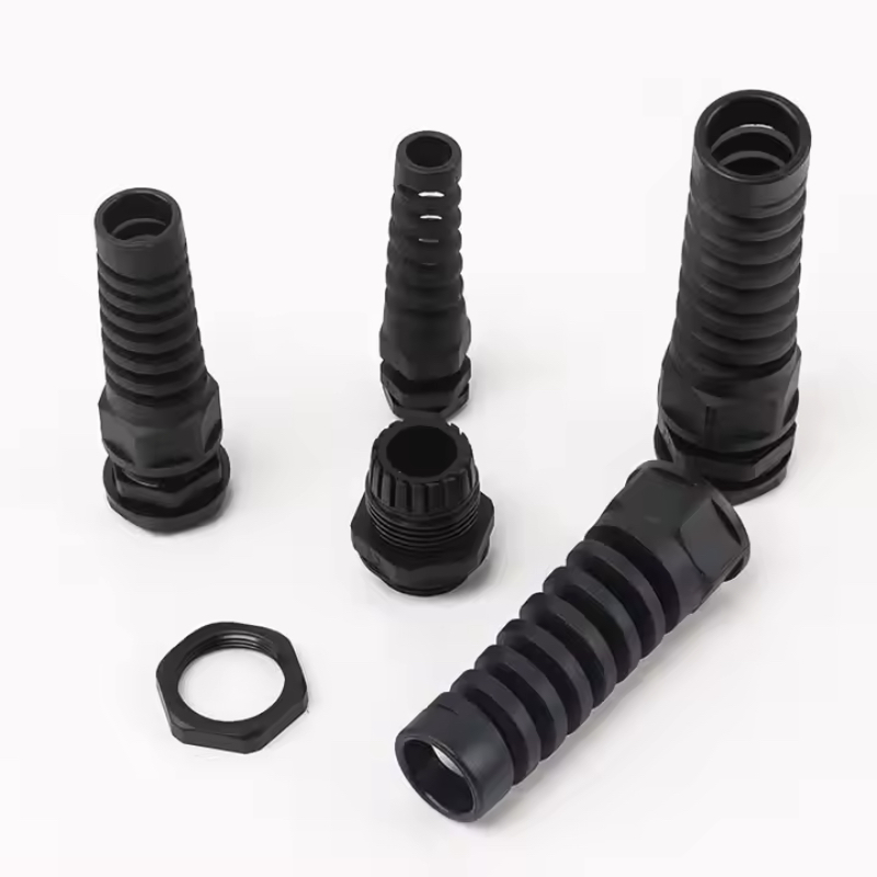
Fiber optic cable glands require specialized design features that standard electrical cable glands simply cannot provide. The delicate nature of optical fibers demands precise bend radius control, superior sealing, and often enhanced vibration resistance.
Unlike traditional electrical cables, fiber optic cables are extremely sensitive to mechanical stress. A standard cable gland that works perfectly for copper conductors can easily damage optical fibers through excessive compression or inadequate bend radius protection. This is why we developed specialized fiber optic glands with integrated strain relief and controlled compression zones.
Key Differentiating Features
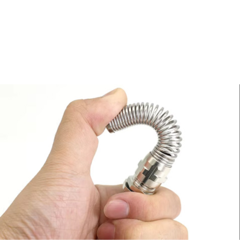
Ochrona przed zginaniem: Fiber optic cables have strict minimum bend radius requirements—typically 10 times the cable diameter for single-mode fibers3 and 20 times for multimode. Our fiber optic glands incorporate curved entry paths and internal guides to maintain these critical specifications.
Controlled Compression: While electrical cables can withstand significant compression forces, optical fibers require gentle, evenly distributed pressure. Specialized sealing systems use soft elastomers and graduated compression to achieve IP68 sealing without fiber damage.
Odporność na wibracje: Telecommunications installations often face continuous vibration from HVAC systems, traffic, or industrial equipment. Enhanced strain relief designs prevent micro-movements that could cause signal degradation over time.
I remember working with David, a network engineer from a major telecom provider in Germany. His team initially tried using standard nylon cable glands for their fiber installation to save costs. Within six months, they experienced intermittent signal losses during temperature changes. After switching to our specialized fiber optic glands with integrated bend radius protection, the issues disappeared completely. 😊
How to Determine Your Environmental Requirements?
Environmental assessment is the foundation of proper gland selection—you must understand temperature ranges, chemical exposure, UV radiation, and ingress protection needs before making any technical decisions.
The environment where your fiber optic cables operate directly impacts material selection, sealing requirements, and long-term reliability. I’ve seen installations fail because engineers didn’t account for seasonal temperature variations or underestimated chemical exposure levels.

Krytyczne czynniki środowiskowe
| Czynnik | Zastosowania wewnętrzne | Outdoor Applications | Industrial Applications |
|---|---|---|---|
| Zakres temperatur | -10°C to +60°C | -40°C do +85°C | -20°C do +120°C |
| Wymagany stopień ochrony IP | IP54 minimum | IP68 essential | IP68 + chemical resistance |
| Odporność na promieniowanie UV | Not required | UV stabilized materials | UV + chemical resistance |
| Poziom wibracji | Niski | Medium (wind/weather) | High (machinery) |
Indoor Installations: Focus on dust protection (IP54 minimum), moderate temperature stability, and easy maintenance access. Nylon glands often provide excellent cost-effectiveness for controlled environments.
Instalacje zewnętrzne: Require maximum ingress protection (IP68), UV-stabilized materials, and wide temperature cycling capability. Stainless steel or UV-resistant nylon compounds are essential.
Środowiska przemysłowe: Demand chemical resistance, high-temperature capability, and enhanced vibration protection. Brass or stainless steel construction with specialized elastomers becomes necessary.
Hassan, who manages a petrochemical facility in Saudi Arabia, learned this lesson the hard way. His initial installation used standard outdoor-rated glands, but the harsh chemical environment degraded the sealing materials within two years. We provided chemical-resistant stainless steel glands with PTFE4 seals, and they’ve performed flawlessly for over five years now.
What Are the Key Technical Specifications?
Cable diameter, thread size, and ingress protection rating form the technical foundation of gland selection—get these wrong, and even the best materials won’t save your installation.
Proper technical specification matching ensures reliable sealing, adequate strain relief, and long-term performance. Each specification serves a critical function in the overall system integrity.
Essential Technical Parameters
Zakres średnic kabli: Most fiber optic cables range from 3mm to 20mm outer diameter. Your gland must accommodate the specific cable size with appropriate sealing range. Our glands typically offer 2-3mm adjustment range per size to handle manufacturing tolerances.
Specyfikacja gwintu: Common options include:
Ingress Protection (IP) Ratings:
- IP54: Dust protected, splash resistant (indoor minimum)
- IP65: Dust tight, water jet resistant (outdoor standard)
- IP68: Dust tight, continuous submersion (marine/industrial)
Specyfikacje wydajności
Zakres temperatur: Verify both operating and storage temperature requirements. Elastomer seals are often the limiting factor—standard NBR seals work to +80°C, while silicone or EPDM extends to +150°C.
Wytrzymałość na rozciąganie: Fiber optic cables require gentler handling than electrical cables. Look for glands rated for 50-100N pull force rather than the 500N+ ratings common for power cables.
Bend Radius Maintenance: Critical for signal integrity. Quality glands maintain minimum bend radius even under installation stress and long-term environmental cycling.
How to Choose the Right Material and Design?
Material selection directly impacts longevity, chemical compatibility, and cost-effectiveness—brass offers durability, stainless steel provides ultimate corrosion resistance, while nylon delivers cost-effective performance for controlled environments.
The material choice affects not just initial cost but long-term maintenance requirements and system reliability. Each material has distinct advantages depending on your application requirements.
Material Comparison
| Materiał | Zalety | Najlepsze aplikacje | Ograniczenia |
|---|---|---|---|
| Nylon PA66 | Cost-effective, lightweight, chemical resistant | Indoor, telecom, data centers | UV degradation, temperature limits |
| Mosiądz (niklowany) | Excellent conductivity, moderate cost, good strength | General outdoor, industrial | Corrosion in marine environments |
| Stal nierdzewna 316L | Superior corrosion resistance, high temperature | Marine, chemical, extreme environments | Higher cost, weight |
Nylon Advantages: Our glass-filled PA66 glands offer excellent chemical resistance, lightweight installation, and cost-effectiveness for indoor applications. The material naturally dampens vibration and provides good insulation properties.
Brass Benefits: Nickel-plated brass combines mechanical strength with moderate corrosion resistance. The material offers excellent threading durability and maintains consistent torque specifications over time.
Stainless Steel Applications: When facing saltwater, chemical exposure, or extreme temperatures, 316L stainless steel provides unmatched durability. The material maintains structural integrity across wide temperature ranges and resists virtually all environmental challenges.
Rozważania projektowe
Single vs. Multi-Cable Designs: Single-cable glands offer maximum sealing integrity and individual strain relief. Multi-cable versions reduce enclosure penetrations but require careful cable diameter matching.
Strain Relief Options: Integrated bend radius protection, adjustable strain relief boots, and graduated compression systems all contribute to long-term fiber protection.
Jakich typowych błędów należy unikać?
The most costly mistakes in fiber optic gland selection involve inadequate environmental assessment, improper installation torque, and choosing price over performance for critical applications.
After helping thousands of customers worldwide, I’ve identified recurring mistakes that lead to premature failures, signal degradation, and costly reinstallations.
Critical Mistakes to Avoid
Over-tightening During Installation: Fiber optic cables are delicate. Excessive installation torque can compress optical fibers, causing immediate or gradual signal loss. Always follow manufacturer torque specifications—typically 15-25 Nm for most sizes.
Ignoring Bend Radius Requirements: Sharp bends at the gland entry point cause immediate signal attenuation. Ensure your gland design maintains minimum bend radius throughout the connection zone.
Nieodpowiednia ochrona środowiska: Choosing indoor-rated glands for outdoor applications, or standard materials for chemical environments, leads to premature seal failure and moisture ingress.
Wrong Thread Selection: Mismatched threads create stress concentrations and sealing problems. Verify enclosure thread specifications before ordering glands.
Insufficient Cable Diameter Range: Glands with narrow cable diameter ranges may not accommodate manufacturing tolerances or future cable changes. Select glands with adequate adjustment range.
Najlepsze praktyki instalacji
Always perform a trial fit before final installation. Check that the cable seats properly in the strain relief area and that the sealing system engages correctly across the full cable diameter range. Pre-lubricate O-rings with compatible silicone grease to ensure proper sealing and prevent installation damage.
Wnioski
Selecting the right cable glands for fiber optic applications requires careful consideration of environmental conditions, technical specifications, and material compatibility. Focus on bend radius protection, appropriate ingress protection ratings, and proven sealing systems rather than simply choosing the lowest-cost option.
Remember that fiber optic installations represent significant infrastructure investments. The additional cost of properly specified glands is minimal compared to the expense of signal degradation, system downtime, or complete reinstallation. At Bepto, we’re committed to helping you make the right choice the first time, backed by our comprehensive certifications and proven track record in demanding applications worldwide.
FAQs About Fiber Optic Cable Glands
Q: What’s the difference between fiber optic cable glands and regular electrical cable glands?
A: Dławnice światłowodowe zapewniają specjalistyczną ochronę promienia gięcia i łagodniejszą kompresję, aby zapobiec uszkodzeniu światłowodu, podczas gdy dławnice elektryczne koncentrują się głównie na uszczelnieniu i odciążeniu bez tych krytycznych funkcji ochrony światłowodu.
P: Jak określić prawidłowy stopień ochrony IP dla mojej instalacji światłowodowej?
A: W zastosowaniach wewnętrznych zazwyczaj wymagany jest minimalny stopień ochrony IP54, instalacje zewnętrzne wymagają stopnia ochrony IP68, a środowiska przemysłowe mogą wymagać stopnia ochrony IP68 oraz odporności chemicznej w zależności od warunków narażenia.
P: Czy mogę użyć tego samego dławika kablowego do różnych typów kabli światłowodowych?
A: Yes, if the cable outer diameters fall within the gland’s sealing range and the bend radius requirements are met. However, verify that armored cables don’t require specialized grounding provisions.
P: Jakiego momentu obrotowego należy użyć podczas instalacji dławików światłowodowych?
A: Większość dławnic światłowodowych wymaga momentu obrotowego instalacji 15-25 Nm, znacznie mniejszego niż w przypadku dławnic kabli elektrycznych. Zawsze należy zapoznać się ze specyfikacjami producenta i używać skalibrowanego klucza dynamometrycznego, aby zapobiec nadmiernemu ściśnięciu.
P: Jak często należy sprawdzać lub wymieniać dławnice kabli światłowodowych?
A: Sprawdzaj integralność uszczelnienia co roku w zastosowaniach zewnętrznych, co 2-3 lata w instalacjach wewnętrznych. Wymień natychmiast, jeśli zauważysz degradację uszczelnienia, luźne połączenia lub jakiekolwiek oznaki wnikania wilgoci w okolice dławika.
-
Zobacz oficjalną definicję stopnia ochrony IP68, który oznacza ochronę przed pyłem i ciągłym zanurzeniem w wodzie. ↩
-
Understand why maintaining a minimum bend radius is critical for the performance and reliability of fiber optic cables. ↩
-
Explore the key differences in construction, application, and performance between single-mode and multimode fibers. ↩
-
Discover the technical properties of Polytetrafluoroethylene (PTFE), known for its exceptional chemical and thermal resistance. ↩
-
Poznaj specyfikacje i zastosowania amerykańskiego standardu NPT (National Standard Pipe Thread). ↩
