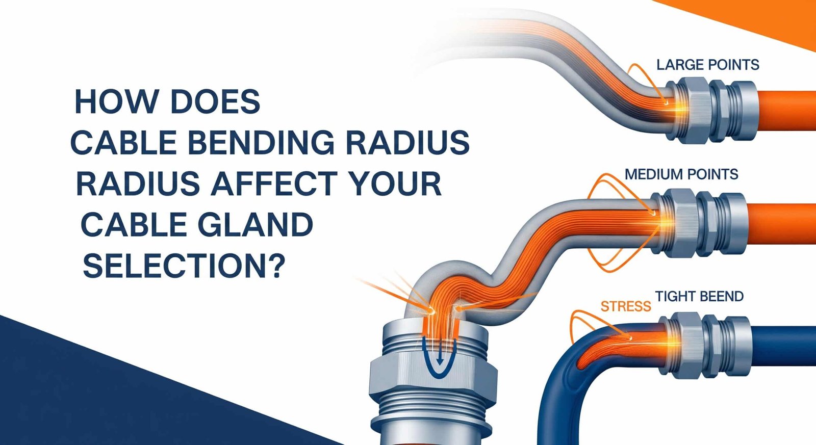
Improper cable bending creates stress concentrations that damage conductors, compromise insulation integrity, and cause premature cable failures, while inadequate bending radius calculations lead to installation problems, reduced cable life, and safety hazards that can result in system downtime and costly repairs. Many installers underestimate the critical relationship between cable bending radius and cable gland selection, leading to installations that appear correct but fail prematurely due to mechanical stress and strain relief inadequacies.
Cable bending radius directly impacts cable gland selection by determining minimum bend requirements, strain relief needs, and installation space requirements, with proper selection requiring understanding of cable construction, environmental conditions, and mechanical stress factors to ensure reliable long-term performance and prevent cable damage during installation and operation. The relationship between bending radius and gland design is fundamental to successful cable management systems.
Having worked with electrical contractors across major automotive plants in Detroit, data centers in Frankfurt, and petrochemical facilities throughout the Middle East, I’ve seen how proper understanding of cable bending radius can prevent costly installation mistakes and ensure reliable system performance. Let me share the essential knowledge for selecting cable glands that properly accommodate your cable bending requirements.
Spis treści
- What Is Cable Bending Radius and Why Does It Matter?
- How Do You Calculate Minimum Bending Radius for Different Cable Types?
- What Cable Gland Features Support Proper Bending Radius Management?
- How Do Environmental Factors Affect Bending Radius Requirements?
- What Are the Best Practices for Installation and Long-Term Performance?
- FAQs About Cable Bending Radius
What Is Cable Bending Radius and Why Does It Matter?
Cable bending radius1 is the minimum radius a cable can be bent without damaging its internal structure, affecting conductor integrity, insulation performance, and overall cable life, making it a critical factor in cable gland selection because inadequate bending radius support leads to stress concentrations, premature failures, and safety hazards in electrical installations.
Understanding bending radius fundamentals is essential because even high-quality cables and glands will fail if basic mechanical principles are ignored during design and installation.
Mechanical Stress Fundamentals
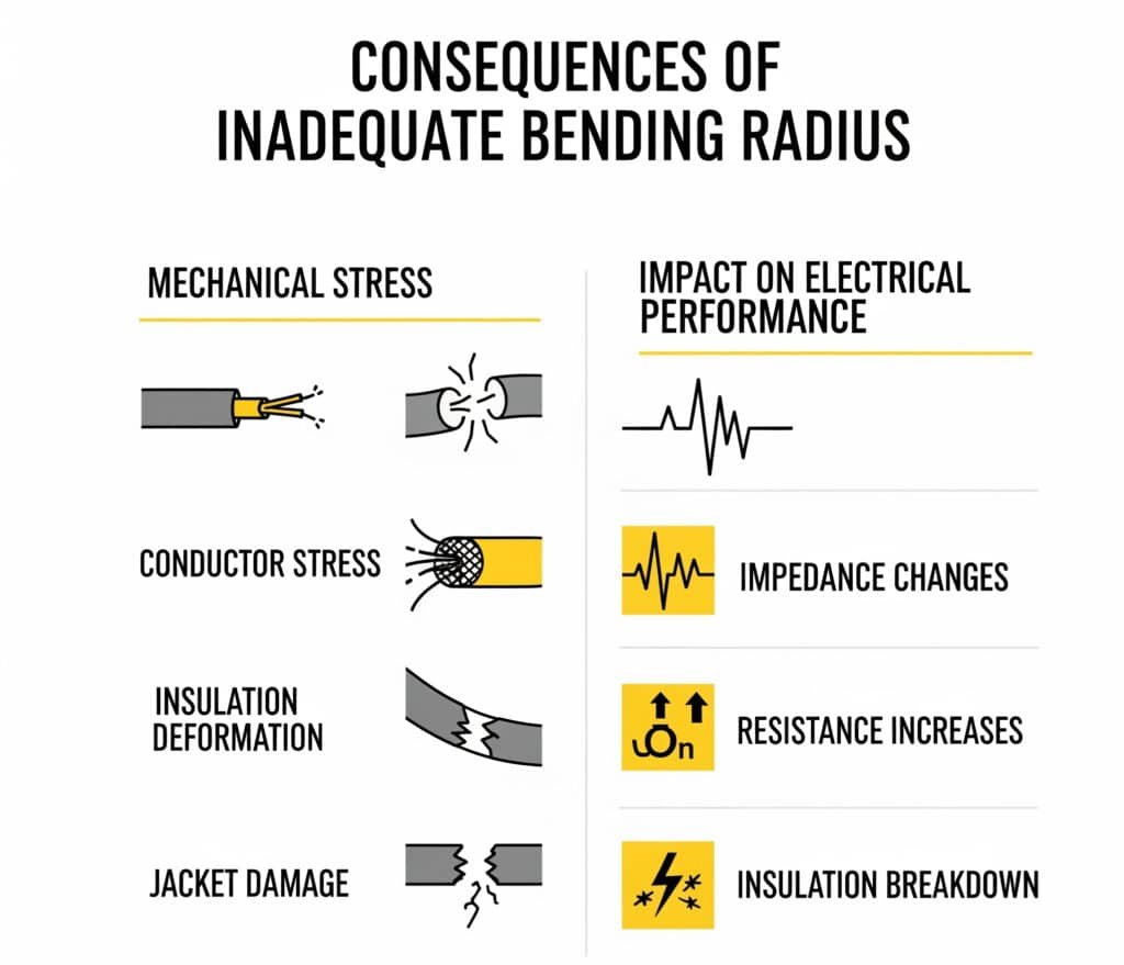
Conductor Stress: When cables bend, outer conductors experience tensile stress while inner conductors face compressive forces, with excessive bending causing conductor breakage, work hardening2, and eventual failure.
Insulation Deformation: Cable insulation stretches on the outer radius and compresses on the inner radius during bending, with tight bends causing permanent deformation, cracking, and reduced wytrzymałość dielektryczna3.
Shielding Integrity: Cable shielding systems experience differential stress during bending, potentially causing shield discontinuities that compromise EMC performance and create safety hazards.
Uszkodzenie kurtki: Outer cable jackets bear the highest stress during bending, with inadequate radius causing surface cracking, environmental seal loss, and accelerated aging.
Impact on Electrical Performance
Impedance Changes: Tight bends alter cable geometry and conductor spacing, causing impedance variations that affect signal integrity in data and communication cables.
Capacitance Variations: Bending changes the relationship between conductors and ground planes, creating capacitance variations that can cause signal reflections and timing issues.
Resistance Increases: Conductor deformation from excessive bending increases electrical resistance, causing voltage drops, power losses, and heat generation.
Insulation Breakdown: Stressed insulation has reduced breakdown voltage and increased leakage current, creating safety hazards and reliability issues.
Long-Term Reliability Consequences
Fatigue Failures: Repeated flexing at inadequate bending radius causes fatigue failures in conductors and insulation, leading to intermittent faults and eventual complete failure.
Environmental Ingress: Jacket damage from improper bending allows moisture and contaminants to enter cables, accelerating insulation degradation and corrosion.
Thermal Issues: Increased resistance from bent conductors causes localized heating, accelerating insulation aging and potentially creating fire hazards.
Maintenance Problems: Cables installed with inadequate bending radius are difficult to service and often require complete replacement rather than repair.
David, a procurement manager for a major automotive manufacturer in Stuttgart, Germany, faced recurring cable failures in robotic welding systems where space constraints forced tight cable routing. His maintenance team was replacing cables every 8-12 months due to conductor breakage and insulation failures at bend points. We analyzed the installation and found cables were being bent to half their minimum radius specification. By selecting right-angle cable glands and redesigning the cable routing with proper bend radius support, we extended cable life to over 3 years and eliminated 90% of the cable-related downtime. The initial investment in proper cable glands paid for itself within six months through reduced maintenance costs. 😊
How Do You Calculate Minimum Bending Radius for Different Cable Types?
Calculating minimum bending radius requires understanding cable construction, conductor materials, insulation types, and application requirements, with standard calculations based on cable outer diameter multiplied by construction-specific factors ranging from 4x for flexible cables to 15x for rigid constructions, while considering dynamic vs. static bending requirements and environmental conditions.
Proper calculation is critical because using generic rules of thumb can lead to either over-conservative designs that waste space or under-specified installations that cause premature failures.
Standardowe metody obliczeniowe
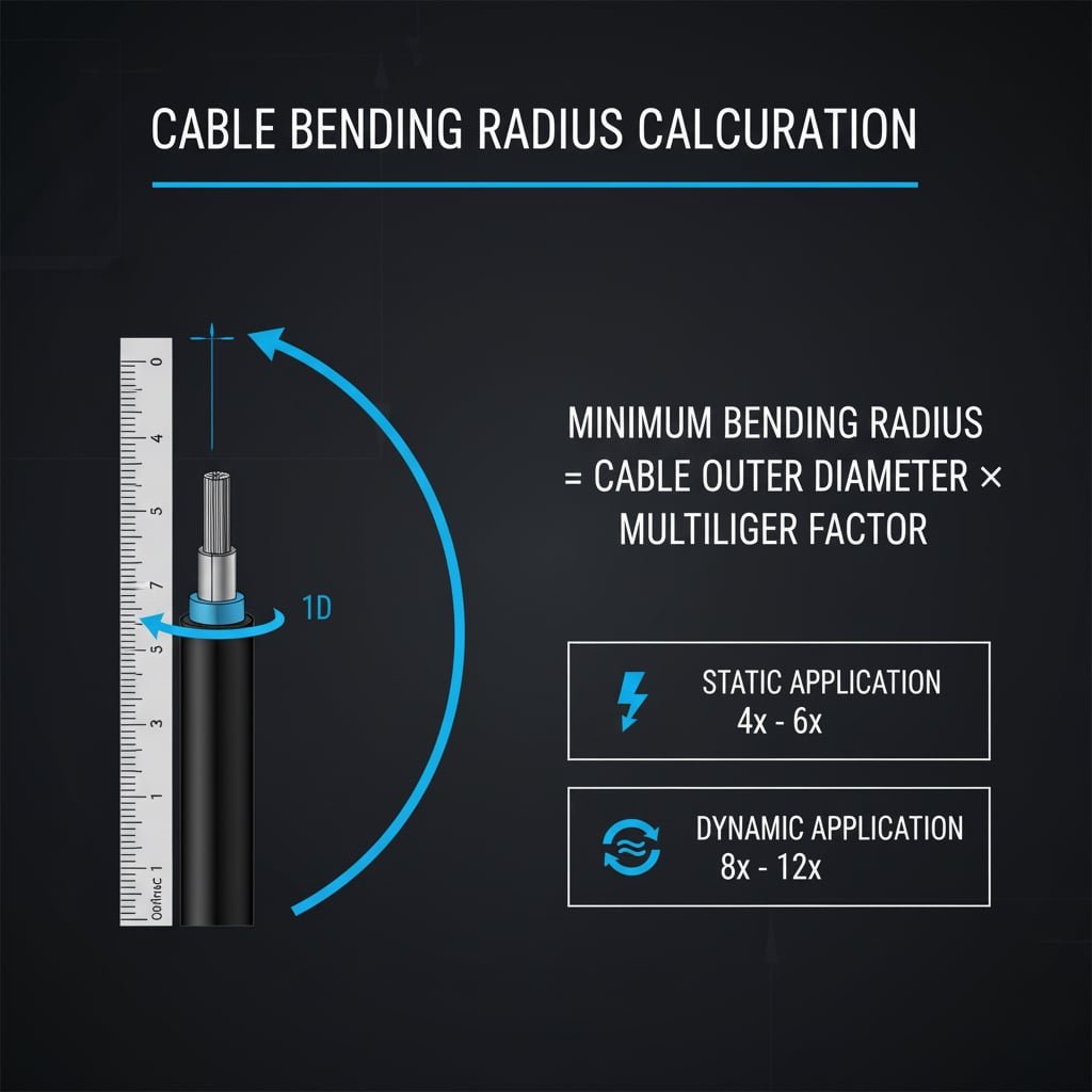
Basic Formula: Minimum bending radius = Cable outer diameter × Multiplier factor, where the multiplier depends on cable construction, conductor type, and application requirements.
Static vs. Dynamic Bending: Static installations (permanent bends) typically allow smaller radius than dynamic applications (repeated flexing), with dynamic applications requiring 2-3 times larger radius.
Installation vs. Operating Radius: Temporary bending during installation may allow smaller radius than permanent operating conditions, but installation stress must still be controlled to prevent damage.
Rozważania dotyczące temperatury: Cold temperatures increase cable stiffness and require larger bending radius, while high temperatures may soften insulation and allow smaller radius with proper support.
Wymagania dotyczące typu kabla
Power Cables (600V-35kV):
- Single conductor: 8-12 times outer diameter
- Multi-conductor: 6-10 times outer diameter
- Armored cables: 12-15 times outer diameter
- High voltage: 15-20 times outer diameter
Control and Instrumentation Cables:
- Flexible control: 4-6 times outer diameter
- Shielded pairs: 6-8 times outer diameter
- Multi-pair data: 4-6 times outer diameter
- Thermocouple: 5-7 times outer diameter
Communication Cables:
- Ethernet/Cat6: 4-6 times outer diameter
- Coaxial: 5-7 times outer diameter
- Fiber optic4: 10-20 times outer diameter
- Tray cable: 6-8 times outer diameter
Specialty Applications:
- Marine cables: 8-12 times outer diameter
- Mining cables: 10-15 times outer diameter
- Robotics cables: 3-5 times outer diameter
- Solar DC cables: 5-8 times outer diameter
Environmental and Application Factors
Wpływ temperatury: Low temperatures increase cable stiffness requiring larger bending radius, while manufacturer specifications typically assume 20°C (68°F) ambient conditions.
Wibracje i ruch: Applications with vibration or repeated movement require larger bending radius to prevent fatigue failures and maintain long-term reliability.
Narażenie chemiczne: Aggressive chemicals can soften or harden cable jackets, affecting flexibility and requiring adjusted bending radius calculations.
UV and Weather Exposure: Outdoor installations may experience jacket hardening from UV exposure, requiring larger bending radius over time.
Calculation Example Table
| Typ kabla | Diameter | Static Multiplier | Dynamic Multiplier | Min. Radius (Static) | Min. Radius (Dynamic) |
|---|---|---|---|---|---|
| 12 AWG THWN | 6 mm | 6x | 10x | 36mm (1.4″) | 60mm (2.4″) |
| 4/0 AWG Power | 25 mm | 8x | 12x | 200mm (7.9″) | 300mm (11.8″) |
| Cat6 Ethernet | 6 mm | 4x | 8x | 24mm (0.9″) | 48mm (1.9″) |
| RG-6 Coax | 7 mm | 5x | 10x | 35mm (1.4″) | 70mm (2.8″) |
| 2/0 Armored | 35 mm | 12x | 18x | 420mm (16.5″) | 630mm (24.8″) |
What Cable Gland Features Support Proper Bending Radius Management?
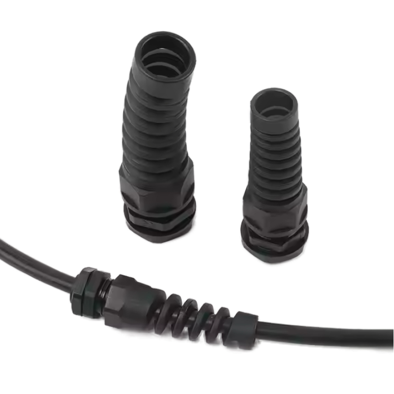
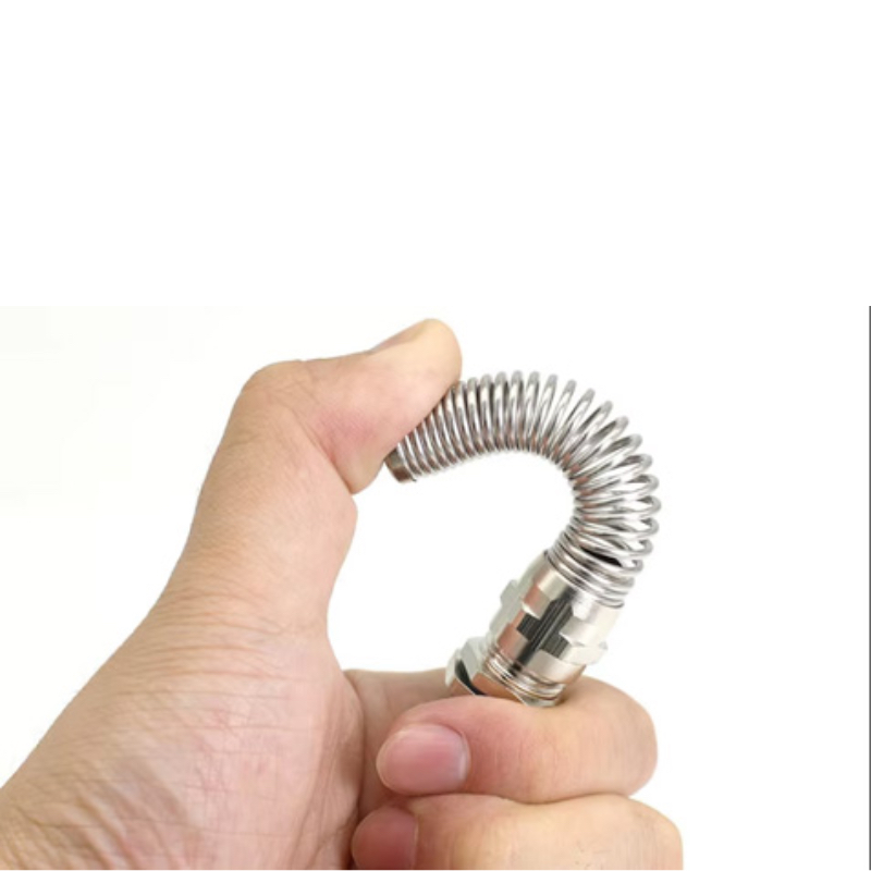
Cable glands that support proper bending radius include right-angle designs, extended strain relief systems, flexible conduit connections, and adjustable entry angles that accommodate installation constraints while maintaining minimum bend requirements, with specialized features like bend restrictors, cable guides, and multi-directional entries providing optimal cable protection.
Selecting glands with appropriate bending radius support is essential because even proper calculations are useless if the cable gland design forces cables into tight bends at the connection point.
Right-Angle Cable Gland Designs
90-Degree Entries: Pre-formed right-angle entries eliminate sharp bends at the gland connection point, providing smooth cable transition that maintains proper bending radius throughout the connection.
45-Degree Entries: Angled entries provide compromise between space savings and bending radius requirements, suitable for applications with moderate space constraints.
Variable Angle Designs: Adjustable entry angles allow optimization for specific installation requirements, providing flexibility while maintaining proper cable support.
Integrated Bend Support: Internal radius supports within the gland body ensure cables maintain proper curvature even under mechanical stress or thermal cycling.
Strain Relief and Cable Support Systems
Extended Strain Relief: Longer strain relief sections distribute bending stress over greater cable length, reducing stress concentrations and improving long-term reliability.
Progressive Stiffness: Strain relief systems with graduated stiffness provide smooth transition from rigid gland body to flexible cable, preventing stress concentration points.
Multi-Point Support: Multiple support points along the strain relief length ensure even stress distribution and prevent cable kinking under load.
Removable Strain Relief: Replaceable strain relief components allow maintenance and upgrade without complete gland replacement, reducing long-term costs.
Flexible Connection Systems
Liquid-Tight Connectors: Flexible metal or polymer conduit connections provide excellent bending radius accommodation while maintaining environmental sealing.
Bellows Connections: Accordion-style flexible connections absorb movement and vibration while maintaining proper cable bending radius and environmental protection.
Universal Joint Designs: Articulated connections allow multi-directional movement while supporting proper cable bending throughout the range of motion.
Spring-Loaded Systems: Spring mechanisms maintain constant support pressure on cables during thermal expansion and mechanical movement.
Space-Saving Solutions
Compact Right-Angle Designs: Miniaturized right-angle glands provide proper bending radius support in space-constrained applications like control panels and junction boxes.
Stackable Configurations: Multiple cable entries in compact arrangements that maintain individual cable bending radius requirements.
Integrated Cable Management: Built-in cable routing features that guide cables through proper bend radius paths within the gland assembly.
Systemy modułowe: Configurable gland systems that can be customized for specific bending radius and space requirements.
Matryca kryteriów wyboru
| Typ aplikacji | Recommended Gland Features | Bending Radius Benefit | Typowe zastosowania |
|---|---|---|---|
| Panele sterowania | Right-angle, compact design | Saves 60-80% space | Industrial automation |
| Outdoor Enclosures | Extended strain relief | Reduces stress 50% | Weather stations |
| Vibration Environments | Elastyczne połączenia | Prevents fatigue failure | Sprzęt mobilny |
| High-Density Installations | Stackable, multi-entry | Optimizes cable routing | Centra danych |
| Dostęp serwisowy | Removable strain relief | Enables service | Sprzęt procesowy |
Hassan, who manages a petrochemical facility in Jubail, Saudi Arabia, needed to upgrade control system cabling in existing control rooms where space constraints made proper cable bending radius nearly impossible with standard cable glands. The original installation used straight glands that forced cables into tight 90-degree bends immediately at the panel entry, causing frequent cable failures and maintenance issues. We provided compact right-angle cable glands with integrated strain relief that maintained proper bending radius while reducing the required panel space by 70%. The installation eliminated cable stress points and reduced cable-related maintenance calls by 85%, while the improved cable management also enhanced the professional appearance of the control room.
How Do Environmental Factors Affect Bending Radius Requirements?
Environmental factors significantly impact bending radius requirements through temperature effects on cable flexibility, chemical exposure affecting jacket properties, UV degradation changing material characteristics, and mechanical stresses from vibration and movement that require increased safety margins in bending radius calculations to ensure reliable long-term performance.
Understanding environmental impacts is crucial because cable and gland specifications are typically based on standard laboratory conditions that may not reflect actual installation environments.
Temperature Effects on Cable Flexibility
Low Temperature Impact: Cold temperatures increase cable stiffness dramatically, with some cables becoming 3-5 times stiffer at -40°C compared to room temperature, requiring proportionally larger bending radius.
Efekty wysokiej temperatury: Elevated temperatures soften cable jackets and insulation, potentially allowing smaller bending radius but also reducing mechanical strength and increasing deformation risk.
Thermal Cycling Stress: Repeated temperature changes cause expansion and contraction that creates additional stress at bend points, requiring larger safety margins in bending radius calculations.
Installation Temperature: Cables installed in cold conditions may crack or damage if bent to warm-weather specifications, requiring temperature-adjusted installation procedures.
Chemical and Environmental Exposure
Chemical Softening: Some chemicals soften cable jackets, reducing mechanical strength and requiring larger bending radius to prevent permanent deformation.
Chemical Hardening: Other chemicals cause jacket hardening that increases stiffness and requires larger bending radius than original specifications.
Ozone and UV Exposure: Outdoor installations experience jacket degradation that changes flexibility characteristics over time, requiring periodic reassessment of bending capabilities.
Moisture Effects: Water absorption can change cable jacket properties, affecting flexibility and requiring adjusted bending radius calculations for wet environments.
Mechanical Stress Considerations
Vibration Environments: Continuous vibration creates fatigue stress that requires larger bending radius to prevent premature failure, typically 1.5-2 times static requirements.
Dynamic Movement: Applications with regular cable movement need significantly larger bending radius to accommodate repeated flexing without fatigue failure.
Installation Stress: Temporary installation stresses during cable pulling and routing must be considered, often requiring larger radius during installation than final operating conditions.
Support System Effects: Cable tray systems, conduits, and other support structures affect bending stress distribution and may require adjusted radius calculations.
Environmental Adjustment Factors
Temperature Adjustment Table:
- -40°C to -20°C: Multiply standard radius by 2.0-2.5
- -20°C to 0°C: Multiply standard radius by 1.5-2.0
- 0°C to 20°C: Use standard radius specifications
- 20°C to 60°C: May reduce radius by 10-20% with proper support
- Above 60°C: Requires specialized high-temperature calculations
Chemical Exposure Adjustments:
- Mild chemical exposure: Add 20-30% safety margin
- Moderate exposure: Add 50-75% safety margin
- Severe exposure: Requires specialized cable and gland materials
- Unknown chemicals: Use maximum safety margins until testing confirms compatibility
Vibration and Movement Adjustments:
- Low vibration (< 2g): Add 25% safety margin
- Moderate vibration (2-5g): Add 50% safety margin
- High vibration (> 5g): Add 100% safety margin
- Continuous flexing: Use dynamic bending specifications
Long-Term Performance Considerations
Efekty starzenia: Cable jackets become stiffer with age, requiring larger bending radius over time or planned replacement schedules.
Dostęp serwisowy: Environmental conditions may limit maintenance access, requiring more conservative bending radius specifications to extend service life.
System Expansion: Future cable additions or modifications may require different routing, necessitating flexible bending radius accommodation in original design.
Monitorowanie wydajności: Regular inspection programs should monitor cable condition at bend points to identify environmental effects before failures occur.
What Are the Best Practices for Installation and Long-Term Performance?
Best practices for cable bending radius management include pre-installation planning, proper cable routing design, use of appropriate support systems, regular inspection programs, and documentation of installation parameters to ensure long-term reliability and enable effective maintenance throughout the system lifecycle.
Following systematic best practices is essential because even perfect calculations and component selection can be undermined by poor installation techniques or inadequate maintenance planning.
Planowanie przed instalacją
Cable Route Surveying: Detailed measurement and documentation of cable routes to identify potential bending radius constraints before cable ordering and installation begins.
Space Allocation: Adequate space reservation for proper cable bending radius, including consideration of future cable additions and maintenance access requirements.
Support System Design: Proper specification and installation of cable trays, conduits, and other support systems that maintain bending radius throughout the cable run.
Installation Sequence Planning: Coordination of cable installation sequence to prevent interference and ensure proper bending radius for all cables in multi-cable installations.
Techniki instalacji
Cable Handling Procedures: Proper techniques for cable handling during installation to prevent damage from excessive bending, twisting, or tension.
Pulling Tension Control: Monitoring and limiting cable pulling tension to prevent conductor damage and ensure cables can achieve proper bending radius after installation.
Temporary Support Systems: Use of temporary guides and supports during installation to maintain proper bending radius before permanent support systems are in place.
Punkty kontrolne kontroli jakości: Regular inspection during installation to verify bending radius compliance and identify potential issues before completion.
Support System Implementation
Cable Tray Selection: Proper tray width, depth, and bend radius specifications to accommodate all cables with appropriate safety margins.
Conduit Sizing: Adequate conduit diameter and bend radius to prevent cable damage during installation and allow proper cable positioning.
Strain Relief Installation: Proper installation and adjustment of cable gland strain relief systems to provide optimal cable support without over-constraint.
Vibration Isolation: Implementation of vibration isolation systems in environments where mechanical stress could affect cable bending performance.
Maintenance and Monitoring Programs
Regularne harmonogramy inspekcji: Systematic inspection of cable bend points to identify early signs of stress, damage, or performance degradation.
Testowanie wydajności: Periodic electrical testing to identify performance changes that might indicate cable stress or damage at bend points.
Monitorowanie środowiska: Tracking environmental conditions that could affect cable flexibility and bending radius requirements over time.
Documentation Updates: Maintaining current records of cable installations, modifications, and performance history to support maintenance planning.
Installation Best Practices Checklist
Planning Phase:
- Calculate minimum bending radius for all cable types
- Survey installation routes for space constraints
- Select appropriate cable glands and support systems
- Plan installation sequence and procedures
Installation Phase:
- Use proper cable handling techniques
- Monitor pulling tension continuously
- Install temporary supports as needed
- Verify bending radius compliance at each bend point
Completion Phase:
- Document final cable routing and bend locations
- Perform electrical testing to verify performance
- Install permanent identification and warning labels
- Establish maintenance inspection schedule
Long-Term Management:
- Conduct regular visual inspections
- Monitor environmental conditions
- Track performance trends
- Update documentation for any modifications
Wnioski
Understanding cable bending radius and its impact on cable gland selection is fundamental to creating reliable electrical installations that provide long-term performance and safety. Proper bending radius management requires systematic consideration of cable construction, environmental factors, installation constraints, and long-term maintenance requirements.
Success in cable bending radius management comes from thorough planning, appropriate component selection, proper installation techniques, and ongoing maintenance programs. At Bepto, we provide comprehensive cable gland solutions with the technical expertise to help you achieve optimal cable bending radius management, ensuring reliable performance and extended service life for your electrical installations.
FAQs About Cable Bending Radius
Q: What happens if I bend a cable tighter than its minimum radius?
A: Bending cables tighter than minimum radius causes conductor damage, insulation stress, and reduced electrical performance that can lead to premature failure. The damage may not be immediately visible but will cause reliability issues over time.
Q: How do I calculate bending radius for armored cables?
A: Armored cables typically require 12-15 times the outer diameter for minimum bending radius due to the metal armor construction. Always check manufacturer specifications as some armored cables may require even larger radius depending on armor type.
Q: Can I use smaller bending radius if the cable will never move after installation?
A: Static installations may allow slightly smaller radius than dynamic applications, but you should never go below manufacturer minimum specifications. Even static cables experience thermal expansion and vibration that can cause stress at tight bend points.
Q: Do right-angle cable glands eliminate bending radius concerns?
A: Right-angle cable glands help manage bending radius by providing gradual direction changes, but you still need to ensure adequate space for the cable to achieve its minimum bending radius after exiting the gland.
Q: How does temperature affect cable bending radius requirements?
A: Cold temperatures make cables stiffer and require larger bending radius, typically 1.5-2.5 times normal requirements below freezing. Hot temperatures may allow smaller radius but can reduce mechanical strength and increase deformation risk.
-
Learn the industry standards and formulas used to define and calculate minimum bend radius. ↩
-
Understand the material science behind work hardening and how it affects conductor durability. ↩
-
Explore a detailed guide on dielectric strength and how it is measured for electrical insulation. ↩
-
Discover why the glass core of fiber optic cables requires a much larger bend radius than copper. ↩

