
Last winter, I received a distressing call from Robert, a solar installer in Minnesota, who was dealing with multiple connector failures across a 2MW solar farm. After investigating, we discovered that improper strain relief had caused micro-movements in the cables during thermal cycling, leading to contact degradation and power losses exceeding $15,000 monthly. This costly lesson highlights why proper strain relief isn’t just a technical detail—it’s critical for system reliability and profitability.
Pelepasan tegangan yang tepat untuk kabel surya pada konektor melibatkan penggunaan kelenjar kabel yang sesuai, sepatu boot pelepas tegangan, dan metode pengamanan untuk mencegah transfer tegangan mekanis dari pergerakan kabel ke sambungan listrik, memastikan keandalan jangka panjang pada instalasi fotovoltaik di luar ruangan. Effective strain relief protects against thermal expansion, wind loading, and installation stresses that can compromise connector integrity over 25+ year system lifespans.
At Bepto Connector, we’ve witnessed countless installations where inadequate strain relief led to premature failures, warranty claims, and safety hazards. Through our decade of experience in solar connector manufacturing, I’ll share the essential principles and practical techniques that ensure your solar cable connections remain secure and reliable throughout their operational lifetime.
Daftar Isi
- What Is Strain Relief and Why Is It Critical for Solar Connectors?
- What Are the Main Types of Strain Relief Solutions for Solar Applications?
- How Do You Select the Right Strain Relief Method for Your Installation?
- What Are the Best Practices for Installing Strain Relief on Solar Connectors?
- FAQs About Solar Cable Strain Relief
What Is Strain Relief and Why Is It Critical for Solar Connectors?
Strain relief represents one of the most overlooked yet critical aspects of solar connector design, directly impacting system reliability, safety, and long-term performance in demanding outdoor environments.
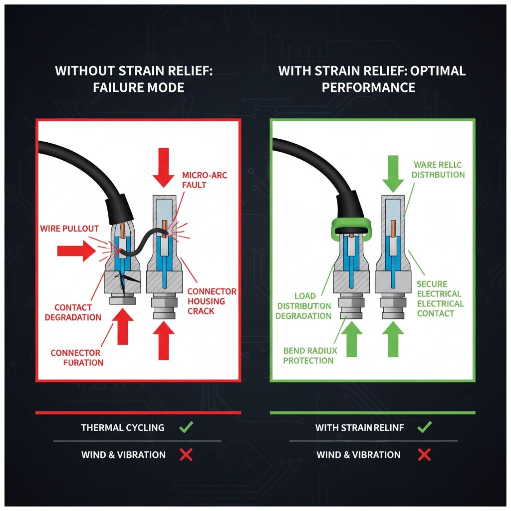
Strain relief prevents mechanical stress from cable movement, thermal expansion, wind loading, and installation forces from transferring to the electrical connection points within solar connectors, protecting against contact degradation, wire pullout, and premature failure. Without proper strain relief, even minor cable movements can cause micro-arcing1, increased resistance, and eventual connector failure.
Understanding Mechanical Stress in Solar Installations
Efek Siklus Termal: Solar cables experience daily temperature variations from -40°C to +90°C, causing expansion and contraction that creates repetitive stress on connections. Without strain relief, this cycling leads to fatigue failure2 of both mechanical and electrical components.
Environmental Loading: Wind forces, ice accumulation, and thermal expansion of mounting structures create dynamic loads that cables must accommodate. Proper strain relief distributes these forces along the cable length rather than concentrating them at the connector interface.
Tekanan Instalasi: Cable routing during installation often requires tight bends and pulling forces that can damage connectors if not properly managed through strain relief systems.
Failure Modes Without Proper Strain Relief
| Jenis Kegagalan | Cause | Konsekuensi | Pencegahan |
|---|---|---|---|
| Wire Pullout | Excessive tension | Open circuit, arc fault | Cable gland with grip |
| Contact Degradation | Micro-movement | Increased resistance, heating | Strain relief boot |
| Kerusakan Isolasi | Sharp bend radius | Ground fault, safety hazard | Perlindungan radius tikungan |
| Connector Housing Crack | Konsentrasi stres | Water ingress, corrosion | Distribusi beban |
Working with Maria, a project manager in Arizona managing a 50MW utility installation, taught me the critical importance of systematic strain relief planning. “Samuel,” she explained during our site visit, “we initially tried to save costs by using basic connectors without integrated strain relief. Within six months, we had over 200 connector failures due to thermal cycling stress. The replacement costs and downtime far exceeded the initial savings from cheaper components.”
Economic Impact of Strain Relief Failures
Biaya Langsung:
- Connector replacement: $50-200 per failure
- Labor costs: $100-500 per repair visit
- System downtime: $500-2000 per day lost generation
- Warranty claims and liability exposure
Biaya Tidak Langsung:
- Reduced system performance and efficiency
- Increased maintenance requirements
- Insurance premium impacts
- Reputation and customer satisfaction issues
Regulatory and Safety Considerations
Proper strain relief is mandated by various electrical codes and safety standards:
NEC Requirements3: Article 690 requires secure cable connections that prevent stress on terminals
Standar IEC: IEC 628524 specifies mechanical endurance requirements for solar connectors
UL Certification: UL 6703 includes strain relief testing as part of connector approval
Persyaratan Asuransi: Many policies require code-compliant installations including proper strain relief
What Are the Main Types of Strain Relief Solutions for Solar Applications?
Solar installations require diverse strain relief solutions tailored to specific cable types, environmental conditions, and mechanical loading requirements, each offering distinct advantages for different applications.
The primary strain relief solutions for solar connectors include integrated cable glands, strain relief boots, cable ties and clamps, flexible conduit systems, and service loops, with selection based on cable diameter, environmental exposure, mechanical loading, and installation accessibility requirements. Each method addresses specific stress patterns and installation challenges common in photovoltaic systems.
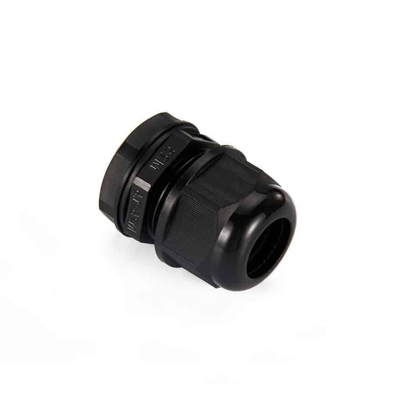
Integrated Cable Glands
Threaded Cable Glands: Most common solution featuring threaded entry with internal gripping mechanism and sealing gasket. Available in metric (M12-M63) and NPT5 (1/2″-2″) thread sizes.
Fitur Utama:
- 360-degree cable grip with rubber or elastomer sealing
- IP68 weatherproof rating when properly installed
- Adjustable compression for various cable diameters
- Compatible with armored and non-armored cables
Aplikasi: Ideal for junction boxes, combiner boxes, and inverter connections where robust sealing and strain relief are required.
Keuntungan: Single component solution, excellent sealing, wide cable diameter range
Keterbatasan: Requires threaded entry port, higher cost than basic solutions
Strain Relief Boots and Grommets
Molded Rubber Boots: Pre-formed elastomer components that slip over cable and connector interface, providing flexibility and weather protection.
Design Variations:
- Straight boots for linear cable runs
- 45° and 90° angled boots for directional changes
- Split boots for retrofit applications
- Heat-shrink boots for permanent installation
Pilihan Bahan:
- EPDM rubber: Excellent UV and ozone resistance
- Silicone: Wide temperature range (-60°C to +200°C)
- TPE (Thermoplastic Elastomer): Good flexibility and durability
- PVC: Cost-effective for indoor applications
Mechanical Securing Systems
Cable Ties and Clamps: Simple, cost-effective solutions for basic strain relief in protected environments.
UV-Resistant Cable Ties:
- Nylon 6.6 with UV stabilizers
- Stainless steel ties for extreme environments
- Releasable ties for maintenance access
- Various lengths and tensile strengths
Cable Clamps and Brackets:
- P-clamps for single cable securing
- Multi-cable clamps for harness management
- Adjustable clamps for various cable sizes
- Vibration-dampening rubber inserts
Hassan, a solar contractor in Saudi Arabia specializing in desert installations, shared his experience with strain relief selection: “In our extreme environment with 50°C temperatures and frequent sandstorms, we learned that standard rubber boots fail within two years. Now we exclusively use silicone strain relief boots with stainless steel cable glands for critical connections. The initial cost is higher, but the reliability improvement has eliminated our callback issues.”
Service Loops and Cable Management
Service Loop Design: Controlled cable routing that provides stress relief through geometric configuration rather than mechanical components.
Prinsip-prinsip Desain:
- Minimum bend radius: 8-10 times cable diameter
- Loop diameter: 12-18 inches for maintenance access
- Secure mounting at multiple points
- Weather-resistant support materials
Cable Tray and Raceway Systems:
- Perforated cable trays for ventilation
- Flexible conduit for protected routing
- Cable ladder systems for large installations
- Expansion joints for thermal movement
Specialized Solutions for Harsh Environments
Marine-Grade Strain Relief: Enhanced corrosion resistance for coastal installations
Cold-Weather Solutions: Flexible materials that remain pliable at low temperatures
Aplikasi Suhu Tinggi: Heat-resistant materials for concentrated solar installations
Explosion-Proof Systems: ATEX/IECEx certified components for hazardous locations
How Do You Select the Right Strain Relief Method for Your Installation?
Selecting appropriate strain relief requires systematic evaluation of environmental conditions, mechanical requirements, cable specifications, and long-term maintenance considerations to ensure optimal performance and cost-effectiveness.
Choose strain relief methods based on cable type and diameter, environmental exposure level, expected mechanical loading, installation accessibility, maintenance requirements, and budget constraints, with integrated solutions preferred for critical applications and simple methods suitable for protected environments. The selection process should consider both initial installation costs and long-term reliability implications.
Matriks Penilaian Lingkungan Hidup
| Faktor Lingkungan | Low Impact | Medium Impact | High Impact | Strain Relief Requirement |
|---|---|---|---|---|
| Paparan sinar UV | Indoor/Shaded | Partial Sun | Direct Sun | Bahan tahan UV |
| Kisaran Suhu | ±20°C | ±40°C | ±60°C | Temperature-rated components |
| Moisture/Humidity | Dry | Occasional | Berkelanjutan | IP65+ sealing required |
| Wind Loading | <50 mph | 50-100 mph | >100 mph | Enhanced securing needed |
| Paparan Bahan Kimia | Tidak ada | Mild | Aggressive | Chemical-resistant materials |
Cable-Specific Selection Criteria
Single Conductor Cables (PV Wire):
- Cable diameter: 4-16 AWG typical
- Flexible construction requires gentle strain relief
- Recommended: Strain relief boots or cable glands
- Avoid: Sharp-edged clamps or excessive compression
Multi-Conductor Cables (AC/DC):
- Larger diameter requires robust strain relief
- Often armored or shielded construction
- Recommended: Threaded cable glands with armor gripping
- Consider: Cable diameter expansion under load
Flexible Cables (Robot/Tracker Applications):
- Continuous flexing requires specialized solutions
- High cycle count requirements (>1 million cycles)
- Recommended: Flexible boots with reinforced construction
- Avoid: Rigid strain relief that restricts movement
Mechanical Loading Analysis
Static Loading: Permanent cable weight and installation tension
- Calculate cable weight per linear foot
- Determine maximum span lengths
- Size strain relief for 3x static load safety factor
Pemuatan Dinamis: Wind, thermal, and operational forces
- Wind loading: Use local building codes (typically 90-150 mph)
- Thermal expansion: Calculate for full temperature range
- Safety factor: 5x for dynamic loading conditions
Fatigue Considerations: Repetitive loading over system lifetime
- Thermal cycles: 9,000+ cycles over 25 years
- Wind cycles: Variable based on location
- Material selection: Fatigue-resistant elastomers
Installation and Maintenance Factors
Persyaratan Aksesibilitas:
- Maintenance frequency and procedures
- Tool access for installation and service
- Component replacement feasibility
- Safety considerations for elevated work
Kompleksitas Instalasi:
- Installer skill level requirements
- Special tools or equipment needed
- Time requirements and labor costs
- Quality control and inspection needs
Working with James, a maintenance supervisor for a 100MW solar facility in Texas, highlighted the importance of maintenance-friendly strain relief design. “We learned the hard way that fancy strain relief systems are worthless if they can’t be serviced safely,” he told me. “Now we specify solutions that can be inspected and replaced without disconnecting the entire string. The slight increase in initial cost pays for itself in reduced maintenance time and improved safety.”
Optimalisasi Biaya-Manfaat
Pertimbangan Biaya Awal:
- Component costs: $5-50 per connection point
- Installation labor: $10-100 per connection
- Special tools or equipment requirements
- Training and certification needs
Analisis Biaya Siklus Hidup:
- Expected service life: 25+ years for quality components
- Maintenance frequency and costs
- Failure rates and replacement costs
- Performance impact of degraded connections
Penilaian Risiko:
- Consequence of failure (safety, financial, regulatory)
- Probability of failure based on application
- Insurance and warranty implications
- Reputation and customer satisfaction impact
What Are the Best Practices for Installing Strain Relief on Solar Connectors?
Proper installation of strain relief systems requires attention to detail, adherence to manufacturer specifications, and understanding of field conditions that affect long-term performance and reliability.
Best practices for strain relief installation include proper cable preparation, correct component sizing, appropriate torque specifications, adequate bend radius maintenance, secure mounting, and comprehensive testing to ensure reliable mechanical and electrical performance throughout the system lifetime. Following systematic installation procedures prevents common failure modes and ensures optimal strain relief effectiveness.
Perencanaan dan Persiapan Pra-Instalasi
Cable Route Planning:
- Identify stress concentration points
- Plan service loops and bend radius requirements
- Determine mounting point locations and spacing
- Consider thermal expansion and contraction paths
Component Selection Verification:
- Confirm cable diameter compatibility
- Verify environmental rating requirements
- Check thread compatibility and sealing requirements
- Ensure adequate grip length and compression range
Tool and Material Preparation:
- Torque wrenches calibrated to specification
- Cable stripping and preparation tools
- Sealants and lubricants as specified
- Safety equipment for elevated work
Urutan dan Teknik Pemasangan
Langkah 1: Persiapan Kabel
- Strip cable jacket to specified length (typically 1-2 inches)
- Remove any sharp edges or burrs
- Clean cable surface of contaminants
- Oleskan pelumas kabel jika ditentukan
Langkah 2: Perakitan Komponen
- Thread strain relief components onto cable in correct order
- Position components at proper locations
- Ensure sealing gaskets are properly seated
- Check for proper orientation and alignment
Step 3: Connection and Securing
- Make electrical connections per manufacturer specifications
- Install strain relief components with proper compression
- Menerapkan nilai torsi yang ditentukan menggunakan alat yang dikalibrasi
- Verify no cable movement at connection points
Parameter Instalasi Kritis
Spesifikasi Torsi:
- Cable gland compression nuts: 15-25 Nm typical
- Strain relief boot clamps: 5-10 Nm typical
- Support bracket fasteners: 20-40 Nm typical
- Always use manufacturer specifications
Bend Radius Requirements:
- Minimum static bend radius: 8x cable diameter
- Dynamic bend radius: 12x cable diameter
- Service loop radius: 6-12 inches minimum
- Avoid sharp edges and stress concentrators
Pedoman Kompresi:
- Cable gland compression: Snug plus 1/4 turn
- Strain relief boots: Firm contact without over-compression
- Cable ties: Tight enough to prevent slippage, not cable deformation
- Visual inspection for proper cable grip
Quality Control and Testing Procedures
Visual Inspection Checklist:
- Proper component orientation and alignment
- No visible cable damage or deformation
- Adequate bend radius at all points
- Secure mounting and support
- Complete weather sealing
Pengujian Mekanis:
- Pull test: Apply 50N force for 1 minute
- No cable movement at connection points
- No component loosening or deformation
- Maintain electrical continuity throughout test
Environmental Verification:
- IP rating confirmation through water spray test
- Temperature cycling verification if required
- UV exposure assessment for material compatibility
- Chemical resistance verification for harsh environments
Common Installation Mistakes and Prevention
Over-Compression Issues:
- Symptom: Cable jacket deformation or conductor damage
- Cause: Excessive torque or wrong component size
- Prevention: Use torque wrench and verify cable diameter
Penyegelan yang Tidak Memadai:
- Symptom: Water ingress and corrosion
- Cause: Missing gaskets or improper assembly
- Prevention: Follow assembly sequence and inspect seals
Insufficient Strain Relief:
- Symptom: Cable movement at connection points
- Cause: Wrong component selection or installation
- Prevention: Verify grip length and compression
Sarah, a quality control manager for a major EPC contractor, emphasized the importance of systematic installation procedures: “We implemented detailed installation checklists and mandatory photos at each step after experiencing field failures due to inconsistent installation quality. Our failure rate dropped by 80% once we standardized the strain relief installation process and provided proper training to all installation crews.”
Documentation and Maintenance Requirements
Dokumentasi Instalasi:
- Component specifications and lot numbers
- Torque values and test results
- Installation photos showing proper assembly
- Installer certification and date
Maintenance Schedule:
- Annual visual inspection of all strain relief components
- Torque verification every 5 years
- Component replacement based on condition assessment
- Documentation of all maintenance activities
Pemantauan Kinerja:
- Electrical connection resistance monitoring
- Thermal imaging for hot spot detection
- Penilaian integritas mekanis
- Environmental degradation tracking
Kesimpulan
Proper strain relief for solar cable connectors is fundamental to system reliability, safety, and long-term performance. The investment in quality strain relief components and proper installation techniques pays dividends through reduced maintenance costs, improved system availability, and enhanced safety. At Bepto Connector, we’ve seen how attention to strain relief details prevents costly failures and ensures solar installations deliver their expected 25+ year performance. Whether you’re installing residential systems or utility-scale projects, never compromise on strain relief quality—your system’s reliability depends on it. Remember that the best connector in the world will fail prematurely without proper strain relief, making this seemingly simple detail one of your most important design decisions.
FAQs About Solar Cable Strain Relief
Q: What happens if I don’t use strain relief on solar connectors?
A: Without strain relief, cable movement transfers stress directly to electrical connections, causing contact degradation, increased resistance, heating, and eventual failure. This can lead to arc faults, fire hazards, and system downtime within months of installation.
Q: How do I know what size strain relief to use for my solar cables?
A: Measure the cable outer diameter and select strain relief components with grip ranges that include your cable size. Typical PV cables range from 10-16 AWG (4-6mm diameter), requiring M12-M20 cable glands or equivalent strain relief boots.
Q: Can I retrofit strain relief to existing solar connector installations?
A: Yes, split strain relief boots and clamp-on cable glands can be retrofitted to existing installations. However, this requires disconnecting power and may be more expensive than proper initial installation with integrated strain relief.
Q: How often should I inspect strain relief components on solar installations?
A: Perform annual visual inspections for damage, loosening, or degradation. In harsh environments or high-wind areas, inspect every 6 months. Replace components showing cracking, hardening, or loss of grip immediately.
Q: What’s the difference between IP65 and IP68 strain relief for solar applications?
A: IP65 provides protection against water jets and is suitable for most solar applications. IP68 offers complete submersion protection and is required for ground-mounted systems prone to flooding or installations in marine environments.
-
Understand the phenomenon of micro-arcing (or fretting corrosion) in electrical contacts and how it leads to connection failure. ↩
-
Explore the concept of fatigue failure, where a material fractures under repeated cyclic loading, even below its static strength limit. ↩
-
Review a summary of the National Electrical Code (NEC) Article 690, which covers the safety standards for solar PV systems. ↩
-
Learn about the international standard IEC 62852, which specifies the safety and performance requirements for DC connectors in photovoltaic systems. ↩
-
See a chart and explanation of the American National Standard Pipe Thread (NPT) standards used for threaded pipes and fittings. ↩
