Bevezetés
Imagine discovering that your “high-performance” EMC cable glands are actually letting through 100 times more electromagnetic interference than specified, causing critical system failures in a hospital’s MRI facility. Without proper transfer impedance testing, you’re essentially flying blind when it comes to shielding effectiveness, potentially exposing sensitive equipment to devastating EMI that could cost millions in downtime and safety risks.
Az átviteli impedancia vizsgálata a külső árnyékolás és a belső vezető közötti elektromos csatolás mérésével ellenőrzött körülmények között számszerűsíti az EMC kábelek árnyékolásának hatékonyságát, amelyet általában milliohm/méterben (mΩ/m) fejeznek ki, az 1 mΩ/m alatti értékek kiváló árnyékolási teljesítményt jeleznek 1 GHz-ig terjedő frekvenciákon, míg a 10 mΩ/m feletti értékek nem megfelelő védelemre utalnak az érzékeny elektronikus alkalmazások esetében. This standardized measurement provides objective data for comparing different EMC gland designs and validating performance claims.
Last year, Marcus, a project engineer at a German automotive testing facility in Stuttgart, faced recurring EMI issues that were invalidating their electromagnetic compatibility tests. Despite using supposedly “premium” EMC cable glands, their anechoic chamber1 was experiencing interference that made accurate measurements impossible. After we conducted comprehensive transfer impedance testing on their existing glands and compared them with our certified EMC solutions, we discovered their previous supplier’s products had transfer impedance values exceeding 15 mΩ/m – completely inadequate for precision testing environments. Our replacement glands achieved 0.3 mΩ/m, solving their interference problems immediately.
Tartalomjegyzék
- What Is Transfer Impedance and Why Does It Matter?
- How Is Transfer Impedance Testing Performed?
- What Transfer Impedance Values Indicate Good Shielding?
- How Do Different EMC Gland Designs Affect Test Results?
- What Are the Key Applications for Transfer Impedance Data?
- GYIK az átviteli impedancia vizsgálatáról
What Is Transfer Impedance and Why Does It Matter?
Transfer impedance represents the fundamental metric for quantifying electromagnetic shielding effectiveness in cable assemblies and EMC glands.
Transfer impedance measures the electrical coupling between a cable’s outer shield and its inner conductor, expressed as the ratio of induced voltage to the current flowing on the shield surface, providing a frequency-dependent characterization of shielding effectiveness that directly correlates to real-world EMI protection performance. Understanding this parameter enables engineers to make informed decisions about EMC gland selection for critical applications.
The Physics Behind Transfer Impedance
Transfer impedance quantifies how effectively a shield prevents electromagnetic coupling:
Mathematical Definition:
- Transfer impedance (ZT) = Induced voltage (V) / Shield current (I)
- Measured in ohms per unit length (Ω/m or mΩ/m)
- Frequency-dependent parameter typically measured from 10 kHz to 1 GHz
- Lower values indicate better shielding effectiveness
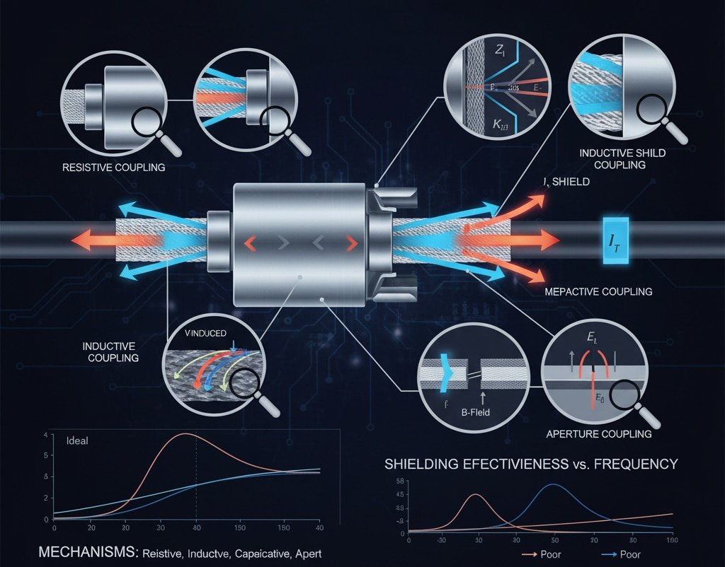
Physical Mechanisms:
- Resistive Coupling: DC resistance of shield material
- Inductive Coupling: Magnetic field penetration through shield gaps
- Capacitive Coupling: Electric field coupling through dielectric materials
- Aperture Coupling2: Electromagnetic leakage through mechanical discontinuities
Why Transfer Impedance Testing Is Critical
Traditional shielding effectiveness measurements often fail to capture real-world performance:
Limitations of Conventional Testing:
- Shielding effectiveness (SE) measurements use idealized test conditions
- Far-field measurements don’t reflect near-field coupling scenarios
- Static measurements miss frequency-dependent behavior
- Doesn’t account for mechanical stress effects on shielding
Transfer Impedance Advantages:
- Directly measures shield-to-conductor coupling
- Reflects actual installation conditions
- Provides frequency-dependent characterization
- Correlates directly with EMI susceptibility levels
- Enables quantitative comparison between different designs
Industry Standards and Requirements
Several international standards govern transfer impedance testing:
Key Standards:
- IEC 62153-4-33: Triaxial method for transfer impedance measurement
- EN 50289-1-6: Test methods for communication cables
- MIL-C-85485: Military specification for EMI/RFI shielding
- IEEE 299: Standard for measuring shielding effectiveness
Typical Requirements by Application:
- Távközlés: < 5 mΩ/m for high-speed data transmission
- Orvosi berendezések: < 1 mΩ/m for MRI and sensitive diagnostic equipment
- Repülés/védelem: < 0.5 mΩ/m for mission-critical systems
- Ipari automatizálás: < 3 mΩ/m for process control applications
How Is Transfer Impedance Testing Performed?
Transfer impedance testing requires specialized equipment and precise measurement techniques to ensure accurate and repeatable results.
Transfer impedance testing is performed using the triaxial method specified in IEC 62153-4-3, where the cable sample is mounted in a precision test fixture with inner conductor, outer shield, and external tube configuration, while a network analyzer injects current into the shield and measures the induced voltage on the inner conductor across frequencies from 10 kHz to 1 GHz. Our laboratory maintains full traceability to international standards for all EMC gland testing.
Test Setup and Equipment
Essential Test Equipment:
- Vector Network Analyzer (VNA)4: Measures complex impedance vs. frequency
- Triaxial Test Fixture: Provides controlled measurement environment
- Precision Coaxial Cables: Minimize measurement uncertainties
- Kalibrációs szabványok: Ensure measurement accuracy and traceability
- Environmental Chamber: Controls temperature and humidity during testing
Test Fixture Configuration:
- Inner Conductor: Connected to VNA port for voltage measurement
- Shield Under Test: Current injection point for transfer impedance measurement
- Outer Tube: Provides reference ground and electromagnetic isolation
- Termination Network: 50-ohm impedance matching for accurate measurements
Step-by-Step Testing Procedure
Minta előkészítése:
- Mount EMC cable gland in standardized test fixture
- Ensure proper electrical connections with specified torque values
- Verify shield continuity and inner conductor isolation
- Document sample configuration and environmental conditions
Calibration Process:
- Perform VNA calibration using precision standards
- Verify test fixture performance with reference samples
- Establish measurement uncertainty and repeatability limits
- Document calibration certificates and traceability chain
Measurement Execution:
- Connect sample to calibrated test system
- Set frequency sweep parameters (typically 10 kHz – 1 GHz)
- Apply specified current levels (typically 100 mA)
- Record transfer impedance magnitude and phase data
- Repeat measurements for statistical validation
Adatelemzés és értelmezés
Raw Data Processing:
- Convert S-parameter measurements to transfer impedance values
- Apply frequency-dependent correction factors
- Calculate measurement uncertainty bounds
- Generate standardized test reports
Teljesítménymérők:
- Peak Transfer Impedance: Maximum value across frequency range
- Average Transfer Impedance: RMS value for broadband assessment
- Frekvenciaválasz: Identification of resonant frequencies
- Phase Characteristics: Important for time-domain performance
Hassan, who manages a petrochemical facility in Dubai, required EMC cable glands for hazardous area applications where both explosion protection and EMI shielding were critical. Standard shielding effectiveness tests couldn’t provide the detailed frequency response data needed for their sophisticated process control systems. Our comprehensive transfer impedance testing revealed that while several competing products met basic shielding requirements, only our ATEX-tanúsítvány5 EMC glands maintained consistent performance below 2 mΩ/m across the entire frequency spectrum, ensuring reliable operation of their critical safety systems in the harsh industrial environment.
What Transfer Impedance Values Indicate Good Shielding?
Understanding transfer impedance benchmarks enables proper EMC gland selection for specific application requirements and performance expectations.
Transfer impedance values below 1 mΩ/m indicate excellent shielding performance suitable for the most demanding applications, values between 1-5 mΩ/m represent good performance for typical industrial applications, while values above 10 mΩ/m suggest inadequate shielding that may compromise system performance in EMI-sensitive environments. Our EMC cable glands consistently achieve values below 0.5 mΩ/m through optimized design and manufacturing processes.

Performance Classification System
| Performance Level | Transfer Impedance Range | Tipikus alkalmazások | Bepto Product Examples |
|---|---|---|---|
| Kiváló | < 1 mΩ/m | Medical, Aerospace, Precision Test | Premium EMC Series |
| Jó | 1-5 mΩ/m | Industrial Automation, Telecommunications | Standard EMC Series |
| Acceptable | 5-10 mΩ/m | General Industrial, Commercial | Basic EMC Series |
| Szegény | > 10 mΩ/m | Nem kritikus alkalmazások | Nem ajánlott |
Frekvenciafüggő megfontolások
Transfer impedance varies significantly with frequency, requiring careful analysis:
Low Frequency Performance (< 1 MHz):
- Dominated by shield resistance
- Material conductivity is primary factor
- Typical values: 0.1-2 mΩ/m for quality EMC glands
- Critical for power frequency interference (50/60 Hz)
Mid Frequency Performance (1-100 MHz):
- Inductive coupling becomes significant
- Shield construction geometry affects performance
- Typical values: 0.5-5 mΩ/m for well-designed glands
- Important for radio frequency interference
High Frequency Performance (> 100 MHz):
- Aperture coupling dominates
- Mechanical precision becomes critical
- Typical values: 1-10 mΩ/m depending on design
- Relevant for digital switching noise and harmonics
Design Factors Affecting Performance
Anyagi tulajdonságok:
- Vezetőképesség: Higher conductivity reduces resistive coupling
- Áteresztőképesség: Magnetic materials provide additional shielding
- Vastagság: Thicker shields generally improve performance
- Felületkezelés: Plating and coatings affect contact resistance
Mechanical Design:
- Contact Pressure: Adequate compression ensures low contact resistance
- 360-Degree Continuity: Eliminates circumferential gaps
- Strain Relief: Prevents mechanical stress on shield connections
- Tömítés kialakítása: Conductive gaskets maintain electrical continuity
Alkalmazás-specifikus követelmények
Orvosi berendezések:
- MRI systems require < 0.1 mΩ/m to prevent image artifacts
- Patient monitoring equipment needs < 0.5 mΩ/m for signal integrity
- Surgical equipment requires < 1 mΩ/m to prevent interference
Távközlés:
- Fiber optic equipment needs < 2 mΩ/m for optical-electrical interfaces
- Base station equipment requires < 3 mΩ/m for signal processing
- Data center applications need < 5 mΩ/m for high-speed digital signals
Ipari automatizálás:
- Process control systems require < 3 mΩ/m for analog signal integrity
- Motor drives need < 5 mΩ/m to prevent switching noise interference
- Safety systems require < 1 mΩ/m for reliable operation
How Do Different EMC Gland Designs Affect Test Results?
EMC cable gland design features directly impact transfer impedance performance, with specific construction elements providing measurable improvements in shielding effectiveness.
Different EMC gland designs significantly affect transfer impedance results, with 360-degree compression designs achieving 0.2-0.8 mΩ/m, spring-finger contacts reaching 0.5-2 mΩ/m, and basic clamp designs typically measuring 2-8 mΩ/m, while advanced multi-stage shielding with conductive gaskets can achieve values below 0.1 mΩ/m for the most demanding applications. Our design optimization focuses on minimizing all coupling mechanisms simultaneously.
Compression-Based Designs
360-Degree Compression Systems:
- Uniform radial compression around entire cable shield
- Eliminates circumferential gaps that cause aperture coupling
- Achieves consistent contact pressure distribution
- Typical performance: 0.2-0.8 mΩ/m across frequency range
Tervezési jellemzők:
- Tapered compression sleeves for gradual pressure application
- Multiple compression zones for redundant shielding
- Strain relief integration prevents stress concentration
- Material selection optimized for conductivity and durability
Spring-Finger Contact Systems
Radial Spring Contacts:
- Multiple spring fingers provide redundant electrical connections
- Self-adjusting contact pressure accommodates cable variations
- Maintains electrical continuity under vibration and thermal cycling
- Typical performance: 0.5-2 mΩ/m depending on finger density
Performance Factors:
- Finger material and plating affect contact resistance
- Contact force distribution influences shielding uniformity
- Number of contact points determines redundancy level
- Mechanical tolerance control ensures consistent performance
Multi-Stage Shielding Approaches
Cascaded Shielding Elements:
- Primary shield connection for main EMI protection
- Secondary gasket seal for additional isolation
- Tertiary barrier for ultimate performance
- Typical performance: < 0.1 mΩ/m for premium designs
Advanced Features:
- Conductive elastomer gaskets for environmental sealing
- Ferrite loading for magnetic field attenuation
- Graded impedance transitions for reflection minimization
- Integrated filtering for specific frequency suppression
Összehasonlító teljesítményelemzés
Design Optimization Trade-offs:
- Cost vs. Performance: Premium designs cost 2-3x more but achieve 10x better shielding
- Installation Complexity: Advanced designs require more precise installation procedures
- Környezeti tartósság: Better shielding designs typically offer superior environmental protection
- Karbantartási követelmények: Higher performance designs often require less frequent maintenance
Frekvenciaválasz jellemzői:
- Simple clamp designs show poor high-frequency performance
- Spring-finger systems maintain consistent mid-frequency response
- Compression designs excel across entire frequency spectrum
- Multi-stage approaches optimize performance for specific applications
Gyártásminőségi hatás
Precision Manufacturing Requirements:
- Dimensional tolerances affect contact pressure uniformity
- Surface finish influences contact resistance
- Assembly procedures impact final performance
- Quality control testing ensures specification compliance
Bepto Manufacturing Advantages:
- CNC machining ensures precise dimensional control
- Automated assembly maintains consistent quality
- 100% electrical testing validates performance
- Statistical process control monitors production variations
What Are the Key Applications for Transfer Impedance Data?
Transfer impedance data serves multiple critical functions in EMC design, specification, and validation processes across various industries and applications.
Transfer impedance data is essential for EMC system design validation, competitive product evaluation, specification compliance verification, failure analysis investigations, and quality control processes, enabling engineers to make data-driven decisions about EMC cable gland selection and optimize overall system electromagnetic compatibility performance. We provide comprehensive test reports with every EMC gland shipment for customer validation.
Design Validation and Optimization
System-Level EMC Modeling:
- Input data for electromagnetic simulation software
- Prediction of overall system shielding effectiveness
- Identification of potential EMI coupling paths
- Optimization of cable routing and grounding strategies
Teljesítmény-előrejelzés:
- Calculation of expected interference levels
- Assessment of safety margins for EMC compliance
- Evaluation of design alternatives before prototyping
- Risk assessment for electromagnetic compatibility
Specification and Procurement
Technical Specification Development:
- Establishment of minimum performance requirements
- Definition of test methods and acceptance criteria
- Creation of quality assurance protocols
- Development of supplier qualification procedures
Supplier Evaluation:
- Objective comparison of competing products
- Verification of manufacturer performance claims
- Assessment of manufacturing consistency and quality
- Long-term supplier performance monitoring
Compliance and Certification
Szabályozási megfelelés:
- Demonstration of EMC directive compliance
- Support for product certification processes
- Documentation for regulatory submissions
- Evidence for electromagnetic compatibility claims
Ipari szabványok:
- Verification of standard compliance (IEC, EN, MIL, etc.)
- Support for third-party certification programs
- Quality system documentation requirements
- Customer specification verification
Failure Analysis and Troubleshooting
Gyökeres okelemzés:
- Investigation of EMI-related system failures
- Identification of shielding degradation mechanisms
- Assessment of installation and maintenance effects
- Development of corrective action plans
Teljesítményfigyelés:
- Tracking of long-term performance trends
- Detection of gradual shielding degradation
- Validation of maintenance and repair procedures
- Optimization of replacement schedules
Quality Control and Manufacturing
Termelési minőségellenőrzés:
- Incoming inspection of EMC components
- Process control for manufacturing operations
- Final product validation before shipment
- Statistical quality monitoring and improvement
Folyamatos fejlesztés:
- Identification of design optimization opportunities
- Validation of manufacturing process improvements
- Benchmarking against competitive products
- Customer satisfaction and performance feedback
Következtetés
Transfer impedance testing represents the gold standard for quantifying EMC cable gland shielding effectiveness, providing the objective data needed to ensure reliable electromagnetic compatibility in critical applications. Through our comprehensive testing capabilities and decade of experience, we’ve proven that proper measurement and specification of transfer impedance can prevent costly EMI failures while optimizing system performance. At Bepto, we don’t just manufacture EMC cable glands – we provide complete electromagnetic compatibility solutions backed by rigorous testing and validation. When you choose our EMC products, you’re getting measurable performance data that gives you confidence in your most demanding applications. Let our transfer impedance expertise help you achieve electromagnetic compatibility success! 😉
GYIK az átviteli impedancia vizsgálatáról
Q: What’s the difference between transfer impedance and shielding effectiveness measurements?
A: Transfer impedance measures direct electrical coupling between shield and conductor, while shielding effectiveness measures far-field electromagnetic attenuation. Transfer impedance provides more accurate real-world performance prediction for cable assemblies and EMC glands in actual installation conditions.
K: Milyen gyakran kell átviteli impedancia vizsgálatot végezni az EMC kábeldugókon?
A: Testing frequency depends on application criticality and environmental conditions. Medical and aerospace applications typically require annual verification, while industrial applications may test every 2-3 years. New product qualification always requires comprehensive testing across the full frequency range.
Q: Can transfer impedance be measured in the field or only in laboratories?
A: Accurate transfer impedance measurement requires specialized laboratory equipment and controlled conditions. Field measurements can provide qualitative assessments but cannot achieve the precision needed for specification compliance or performance validation.
Q: What transfer impedance value should I specify for my application?
A: Specification depends on your EMI sensitivity requirements. Medical equipment typically needs < 1 mΩ/m, industrial automation requires < 3 mΩ/m, and telecommunications applications need < 5 mΩ/m. Consult with EMC experts to determine appropriate values for your specific application.
Q: How does cable type affect transfer impedance test results?
A: Cable construction significantly impacts results – braided shields typically achieve 0.5-2 mΩ/m, foil shields reach 1-5 mΩ/m, and combination shields can achieve < 0.5 mΩ/m. The EMC gland must be optimized for the specific cable shield type to achieve optimal performance.
-
Learn how these specialized rooms are designed to absorb electromagnetic waves for accurate EMC measurements. ↩
-
Understand how gaps and openings in a shield can compromise its effectiveness at high frequencies. ↩
-
Access the official documentation for the triaxial method, the international standard for transfer impedance testing. ↩
-
Explore the principles behind the VNA, a critical instrument for measuring RF performance. ↩
-
Learn about the European Union directives for equipment used in potentially explosive atmospheres. ↩
