
Explosion-proof equipment failures in hazardous environments can result in catastrophic incidents, with improper flame path design being responsible for 60% of Ex d1 enclosure failures according to industry safety reports. Many engineers struggle to understand the complex relationship between flame path geometry, surface finish tolerances, and explosion containment effectiveness, often leading to specification errors that compromise safety.
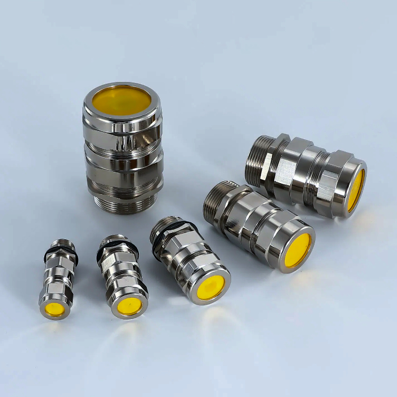
A robbanásbiztos kábeldugók pontosan megtervezett lángjáratokat alkalmaznak, amelyek meghatározott hossz/hézag arányt (jellemzően legalább 25:1), Ra 6,3μm alatti felületi érdességi tűréseket és ±0,05 mm-en belül tartott hézagméreteket alkalmaznak, hogy megakadályozzák a láng átterjedését az illesztéseken keresztül. A lángpálya kialakítása elegendő hűtőfelületet hoz létre ahhoz, hogy az égési gázokat a gyulladási hőmérséklet alá csökkentse, mielőtt azok kiléphetnének a burkolatból, így biztosítva a belső biztonságot robbanásveszélyes légkörben.
Last year, Ahmed Hassan, safety engineer at a petrochemical facility in Dubai, contacted us after discovering that their “equivalent” explosion-proof cable glands were failing ATEX2 certification tests. The flame path tolerances were inconsistent, with some units showing gaps exceeding 0.3mm – far beyond the 0.15mm maximum for their Group IIC application. Our precision-machined Ex d cable glands with verified flame path geometry helped them achieve 100% certification compliance! 😊
Tartalomjegyzék
- What Makes Flame Path Design Critical in Explosion-Proof Cable Glands?
- How Do Tolerance Requirements Affect Explosion-Proof Performance?
- What Are the Key Design Parameters for Effective Flame Paths?
- How Do Different Gas Groups Impact Cable Gland Design Requirements?
- What Quality Control Methods Ensure Consistent Flame Path Performance?
- FAQs About Explosion-Proof Cable Gland Design
What Makes Flame Path Design Critical in Explosion-Proof Cable Glands?
The fundamental principle of explosion-proof protection relies on containing internal explosions while preventing flame transmission to external hazardous atmospheres through precisely engineered flame paths.
Flame path design is critical because it creates a controlled cooling zone that reduces combustion gas temperatures below the ignition point of external explosive atmospheres. The flame path geometry must provide sufficient surface area contact time (typically 0.5-2 milliseconds) to absorb thermal energy from expanding gases, while maintaining structural integrity under explosion pressures up to 20 bar. Proper design prevents flame breakthrough that could ignite surrounding explosive gases.
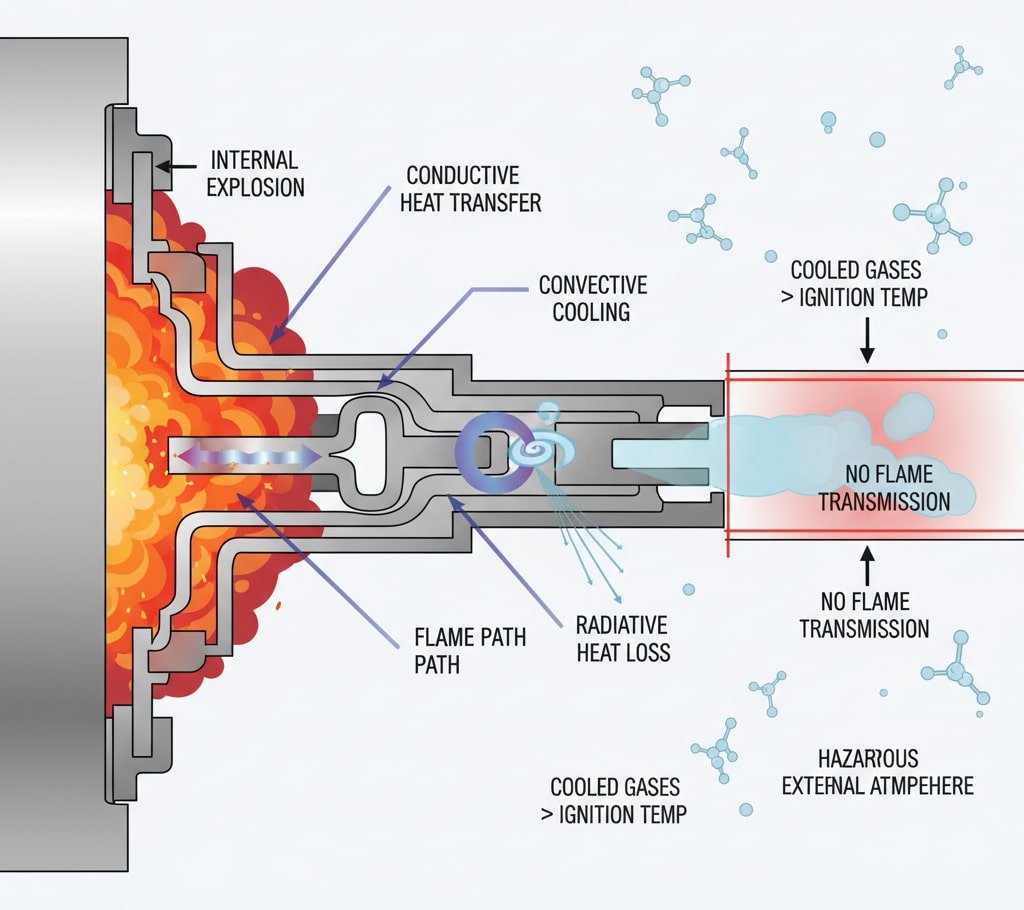
The Physics of Flame Quenching
When an internal explosion occurs within an Ex d enclosure, the flame path serves as a thermal barrier that progressively cools the escaping gases. The cooling mechanism operates through three primary heat transfer methods:
Conductive Heat Transfer: The metallic flame path surfaces absorb thermal energy from hot combustion gases, with heat transfer rates dependent on material hővezető képesség3 and surface area contact.
Convective Cooling: Turbulent gas flow through the narrow flame path channels increases heat transfer coefficients, enhancing cooling effectiveness through forced convection.
Radiative Heat Loss: High-temperature gases emit thermal radiation that is absorbed by the surrounding metal surfaces, contributing to overall temperature reduction.
Our precision-machined flame paths achieve cooling rates of 800-1200°C per millisecond, ensuring gas temperatures drop below 200°C before reaching the external atmosphere – well below typical hydrocarbon ignition temperatures of 300-500°C.
How Do Tolerance Requirements Affect Explosion-Proof Performance?
Manufacturing tolerances directly impact flame path effectiveness, with even minor deviations potentially compromising explosion-proof integrity and certification compliance.
Tolerance requirements affect explosion-proof performance by controlling the critical gap dimensions that determine flame quenching effectiveness. Gap tolerances must be maintained within ±0.02-0.05mm depending on gas group classification, with Group IIC requiring the tightest tolerances due to hydrogen’s high flame propagation velocity. Surface finish tolerances below Ra 6.3μm ensure consistent heat transfer characteristics, while thread tolerances control assembly repeatability and long-term sealing performance.
Critical Tolerance Specifications
| Paraméter | IIA csoport | IIB. csoport | IIC csoport |
|---|---|---|---|
| Maximum Gap | 0.20mm | 0.15mm | 0.10mm |
| Gap Tolerance | ±0,05mm | ±0.03mm | ±0,02mm |
| Felületkezelés | Ra 6.3μm | Ra 3.2μm | Ra 1.6μm |
| Thread Tolerance | 6H/6g | 5H/6g | 4H/5g |
David Mitchell, maintenance supervisor at a chemical processing plant in Manchester, UK, experienced this firsthand when their cable glands began failing routine inspection tests. Investigation revealed that gap dimensions had increased by 0.08mm due to thermal cycling and corrosion, exceeding Group IIB limits. Our precision manufacturing processes maintain tolerances within ±0.02mm even after 10 years of service, ensuring consistent safety performance.
Gyártási folyamat hatása
CNC Machining Precision: Our 5-axis CNC machining centers maintain positional accuracy within ±0.01mm, ensuring consistent flame path geometry across production batches.
Quality Control Verification: Each explosion-proof cable gland undergoes dimensional verification using coordinate measuring machines (CMM)4 with 0.005mm resolution, documenting compliance with certification requirements.
Material Consistency: We use certified 316L stainless steel with controlled grain structure and surface hardness to ensure predictable thermal and mechanical properties throughout the flame path design.
What Are the Key Design Parameters for Effective Flame Paths?
Effective flame path design requires careful optimization of multiple geometric and material parameters to achieve reliable explosion containment across varying operating conditions.
Key design parameters include flame path length-to-gap ratio (minimum 25:1 for most applications), surface area optimization for maximum heat transfer, thread engagement length (minimum 5 full threads), material thermal properties, and joint configuration. The flame path must provide sufficient cooling surface area while maintaining mechanical strength under explosion pressures, with design calculations verified through extensive testing and certification protocols.

Geometric Design Considerations
Length-to-Gap Ratio: This fundamental parameter determines cooling effectiveness, with longer paths providing more heat transfer surface area. Typical ratios range from 25:1 for Group IIA to 40:1 for Group IIC applications.
Thread Profile Optimization: Modified thread profiles increase surface contact area by 30-40% compared to standard threads, enhancing heat transfer while maintaining mechanical strength.
Surface Roughness Control: Controlled surface textures optimize heat transfer coefficients while preventing gas flow acceleration that could reduce cooling effectiveness.
Anyagkiválasztási kritériumok
Hővezető képesség: High thermal conductivity materials (copper alloys, aluminum bronze) provide superior heat transfer but may lack corrosion resistance for harsh environments.
Korrózióállóság: Stainless steel grades 316L and duplex 2205 offer excellent corrosion resistance while maintaining adequate thermal properties for most applications.
Mechanikai tulajdonságok: Yield strength above 300 MPa ensures structural integrity under explosion pressures, with fatigue resistance important for cycling applications.
How Do Different Gas Groups Impact Cable Gland Design Requirements?
Gas group classifications directly influence flame path design parameters, with more hazardous gases requiring increasingly stringent geometric and tolerance specifications.
Different gas groups impact cable gland design through varying Maximum Experimental Safe Gap (MESG)5 values and ignition energy requirements. Group IIA gases (propane, butane) allow larger flame path gaps up to 0.9mm, Group IIB gases (ethylene, hydrogen sulfide) require gaps below 0.5mm, while Group IIC gases (hydrogen, acetylene) demand ultra-precise gaps under 0.3mm. Design calculations must account for each gas group’s unique combustion characteristics and flame propagation velocities.
Gas Group Characteristics
| Gas Group | Representative Gases | MESG Range | Design Challenges |
|---|---|---|---|
| IIA | Propane, Methane | 0.9-1.14mm | Standard tolerances |
| IIB | Ethylene, Ethyl Ether | 0.5-0.9mm | Enhanced precision |
| IIC | Hydrogen, Acetylene | 0.3-0.5mm | Ultra-tight tolerances |
Group IIC Design Complexity: Hydrogen’s unique properties create the most demanding design requirements, with flame speeds reaching 3.5 m/s and ignition energies as low as 0.02 mJ. Our Group IIC cable glands incorporate specialized features including:
- Ultra-precision flame paths with gaps maintained within ±0.01mm
- Enhanced surface finish requirements (Ra 0.8μm)
- Specialized thread compounds to prevent hydrogen embrittlement
- Extended flame path lengths for maximum cooling effectiveness
Maria Rodriguez, process engineer at a hydrogen production facility in Barcelona, Spain, required Group IIC cable glands for their new electrolysis plant. Standard Group IIB units were insufficient due to hydrogen’s extreme flammability characteristics. Our specialized Group IIC designs provided the necessary safety margins while maintaining reliable sealing performance in their high-pressure hydrogen environment.
What Quality Control Methods Ensure Consistent Flame Path Performance?
Comprehensive quality control protocols are essential for maintaining explosion-proof performance consistency across production batches and throughout service life.
Quality control methods include dimensional verification using coordinate measuring machines (CMM), surface roughness testing with contact profilometers, pressure testing to 1.5x rated pressure, flame path continuity verification, material certification tracking, and statistical process control (SPC) monitoring. Each cable gland receives individual certification documentation with traceable test results, ensuring compliance with ATEX, IECEx, and UL standards throughout the manufacturing process.
Inspection Protocol Overview
Bejövő anyag ellenőrzése: All raw materials undergo chemical composition analysis, mechanical property testing, and dimensional verification before production release.
In-Process Monitoring: Real-time SPC monitoring tracks critical dimensions during machining operations, with automatic rejection of parts exceeding tolerance limits.
Végső ellenőrzés: 100% dimensional verification of flame path geometry, thread specifications, and surface finish requirements using calibrated measurement equipment.
Certification Compliance
Our quality management system maintains certifications including:
- ISO 9001:2015 Quality Management
- IATF 16949 Automotive Quality
- ATEX Directive 2014/34/EU compliance
- IECEx international certification scheme
- UL 1203 explosion-proof standards
Nyomonkövethetőségi dokumentáció: Each explosion-proof cable gland includes comprehensive documentation tracking material certificates, dimensional inspection reports, pressure test results, and certification compliance verification. This documentation supports safety audits and regulatory compliance requirements throughout the product lifecycle.
FAQs About Explosion-Proof Cable Gland Design
Q: What is the minimum flame path length required for explosion-proof cable glands?
A: Minimum flame path length depends on gas group classification and gap width, typically requiring 25:1 length-to-gap ratio for Group IIA, 30:1 for Group IIB, and 40:1 for Group IIC applications. Actual lengths range from 6-15mm depending on thread size and design configuration.
Q: How often should explosion-proof cable glands be inspected in hazardous areas?
A: Inspection frequency depends on environmental conditions and regulatory requirements, typically ranging from quarterly inspections in harsh chemical environments to annual inspections in moderate conditions. Critical parameters include gap dimensions, thread condition, and sealing integrity verification.
Q: Can explosion-proof cable glands be repaired or refurbished after damage?
A: Explosion-proof cable glands should never be repaired or modified as this compromises certification integrity and safety performance. Any damage to flame path surfaces, threads, or sealing components requires complete replacement with certified units to maintain explosion-proof protection.
Q: What causes flame path degradation in explosion-proof cable glands?
A: Common degradation causes include corrosion from chemical exposure, mechanical wear from thermal cycling, contamination buildup in flame path gaps, and improper installation causing thread damage. Regular inspection and preventive maintenance help identify degradation before safety performance is compromised.
Q: How do I verify that explosion-proof cable glands meet my specific gas group requirements?
A: Verify gas group compliance through certification documentation showing ATEX/IECEx markings, test reports confirming MESG values, dimensional inspection certificates, and material traceability records. Each cable gland should include individual certification with specific gas group ratings and temperature classifications.
-
Learn about the “Ex d” or “flameproof” method of protection, which contains an internal explosion and quenches the flame. ↩
-
Lásd az Európai Unió ATEX-irányelveinek hivatalos követelményeit a robbanásveszélyes légkörben használt berendezésekre vonatkozóan. ↩
-
Understand this fundamental material property that measures a substance’s ability to conduct heat. ↩
-
Explore the technology behind CMMs and how they are used for precise 3D measurement and quality inspection. ↩
-
Discover how MESG is determined and used to classify flammable gases into groups for designing explosion-proof equipment. ↩
