
When I first started in the solar connector business over a decade ago, I encountered a frustrated installer named Marcus from Germany who was losing sleep over mysterious power drops in his solar installations. His panels were premium quality, his MC4 connectors were properly rated, but something was still wrong. The culprit? Faulty bypass diodes in the junction boxes that were creating bottlenecks in his entire solar array.
Solar panel junction box diodes, specifically bypass diodes, work in conjunction with MC4 connectors to prevent power losses and hot spots1 when individual solar cells are shaded or damaged. These diodes create alternative current paths that maintain system performance while MC4 connectors ensure secure, weatherproof electrical connections between panels.
This is exactly the kind of integration challenge that keeps solar installers awake at night. At Bepto Connector, we’ve seen how the interaction between junction box components and MC4 connectors can make or break a solar installation’s long-term performance. Let me walk you through everything you need to know about this critical relationship.
Sisällysluettelo
- What Are Solar Panel Junction Box Diodes?
- How Do Bypass Diodes Work with MC4 Connectors?
- What Are the Common Problems and Solutions?
- How to Choose the Right Components for Your System?
- FAQs About Solar Panel Junction Box Diodes
What Are Solar Panel Junction Box Diodes?
Solar panel junction boxes contain several critical components, but the bypass diodes are the real heroes of system reliability.
Bypass diodes are semiconductor devices installed in solar panel junction boxes that provide alternative current paths when individual cells or cell strings become shaded or damaged. Without these diodes, a single shaded cell could reduce the output of an entire panel by up to 30%.

The Technical Foundation
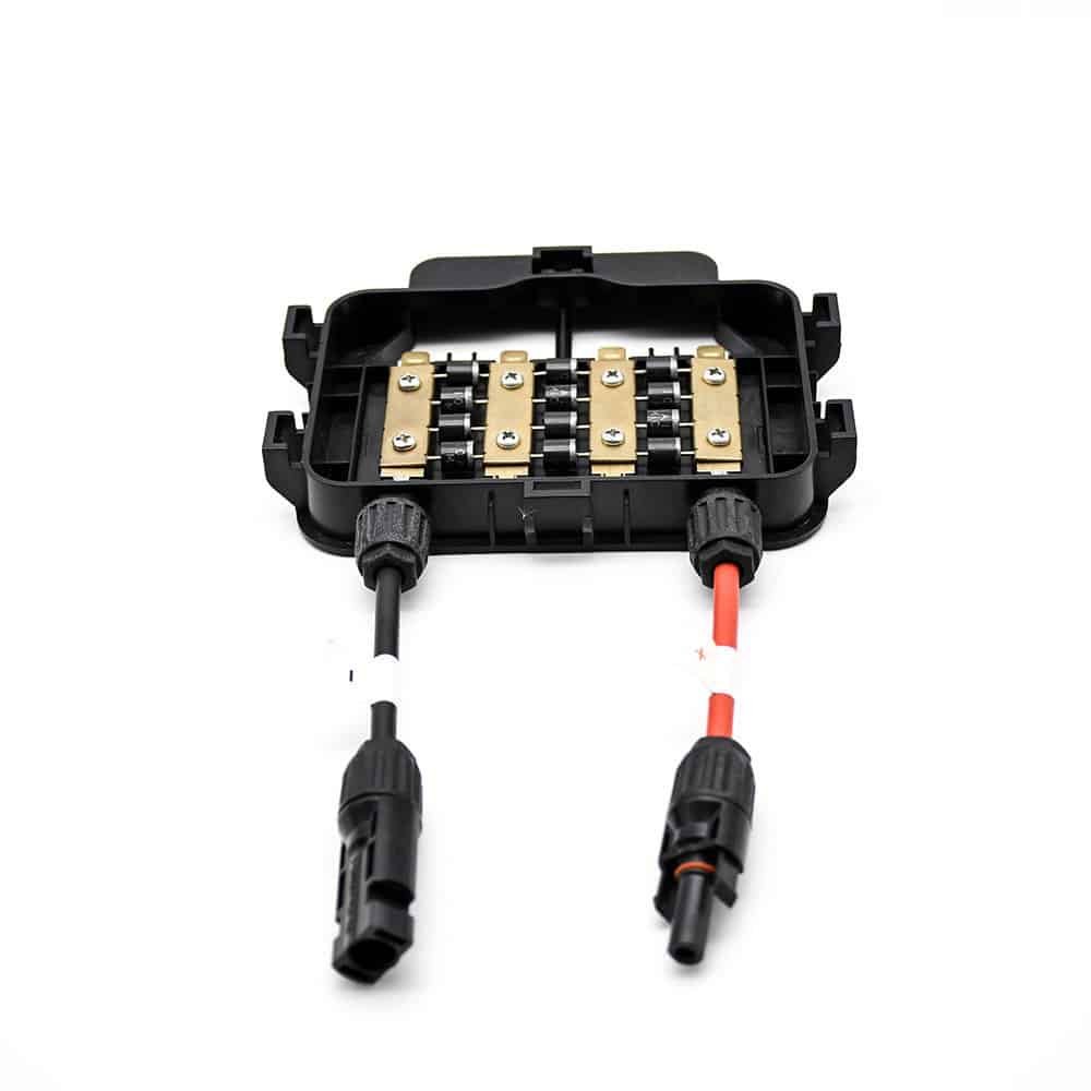
Inside a typical solar panel junction box, you’ll find:
- Bypass Diodes: Usually 2-3 Schottky diodes2 rated for the panel’s current
- Terminal Blocks: Connection points for positive and negative leads
- MC4 Connector Leads: Pre-wired cables terminating in MC4 connectors
- Protective Housing: IP67-rated enclosure protecting internal components
The bypass diodes are strategically connected across groups of solar cells (typically 18-24 cells per diode). When all cells in a group are functioning normally, the diodes remain reverse-biased3 and don’t conduct current. However, when shading or damage occurs, the affected cell group’s voltage drops, forward-biasing the bypass diode and allowing current to flow around the problematic cells.
I remember working with Hassan, a solar farm developer in Dubai, who initially questioned the importance of quality bypass diodes. “Samuel,” he said, “why should I care about a $2 component when my panels cost $200 each?” After experiencing a 15% system-wide power loss due to cheap diode failures during a sandstorm, he became our most vocal advocate for premium junction box components! 😉
How Do Bypass Diodes Work with MC4 Connectors?
The relationship between bypass diodes and MC4 connectors is more interconnected than most installers realize.
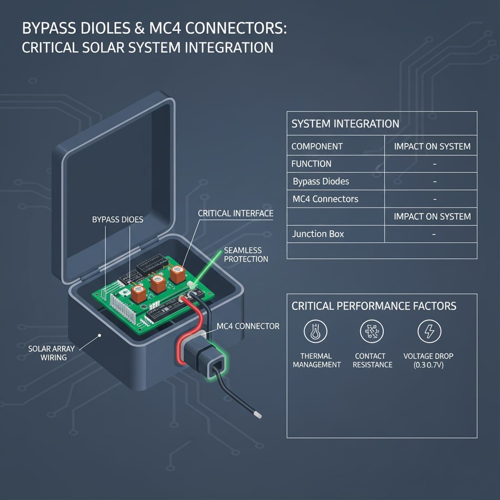
MC4 connectors serve as the critical interface between the junction box’s internal circuitry and the external solar array wiring, ensuring that the bypass diode protection extends seamlessly throughout the entire system. The quality of this connection directly impacts the effectiveness of the bypass diode protection.
The Integration Process
Here’s how these components work together in a typical solar installation:
- Internal Protection: Bypass diodes protect individual cell groups within the panel
- Connection Interface: MC4 connectors provide the transition point from internal to external wiring
- System-Level Protection: The MC4 connection quality affects the overall effectiveness of bypass diode operation
- Seurantaintegraatio: Modern systems can monitor bypass diode operation through the MC4 connection points
| Komponentti | Toiminto | Impact on System |
|---|---|---|
| Bypass Diodes | Prevent hot spots and power loss | Maintains 70-85% power output during partial shading |
| MC4-liittimet | Secure electrical connections | Ensures reliable current flow and system monitoring |
| Liitäntärasia | Houses and protects components | Provides IP67 protection for critical electronics |
Critical Performance Factors
The interaction between these components affects several key performance metrics:
Kosketusvastus4: Poor MC4 connections can create resistance that affects bypass diode operation. We’ve measured systems where corroded MC4 connections increased total system resistance by 15-20%, reducing the effectiveness of bypass diode protection.
Lämmönhallinta: MC4 connectors must handle the current rerouting that occurs when bypass diodes activate. During partial shading conditions, current redistribution can increase connector temperatures by 10-15°C.
Voltage Drop Considerations: The combined voltage drop across MC4 connectors and activated bypass diodes typically ranges from 0.3V to 0.7V, which must be factored into system design calculations.
What Are the Common Problems and Solutions?
After a decade of troubleshooting solar installations worldwide, I’ve identified the most frequent issues that occur at the intersection of junction box diodes and MC4 connectors.
The most common problems include bypass diode failure, MC4 connector corrosion, and thermal cycling stress, all of which can be prevented through proper component selection and installation practices.
Problem #1: Bypass Diode Degradation
Oireet: Gradual power loss, hot spots on panels, inconsistent performance
Root Causes:
- Thermal cycling stress from temperature fluctuations
- Current overload during extended shading periods
- Manufacturing defects in low-quality diodes
Ratkaisumme lähestymistapa:
At Bepto, we recommend using Schottky diodes with at least 25% current derating and temperature coefficients5 suitable for local climate conditions. For desert installations like Hassan’s project in Dubai, we specify diodes rated for 85°C continuous operation with surge protection capabilities.
Problem #2: MC4 Connector Interface Issues
Oireet: Intermittent connections, arcing, accelerated degradation
Root Causes:
- Inadequate IP rating for environmental conditions
- Poor crimping techniques during installation
- Thermal expansion mismatches between connector and junction box
Ennaltaehkäisystrategia:
We always recommend MC4 connectors with matching thermal expansion coefficients to the junction box materials. Our testing shows that mismatched materials can create stress concentrations leading to seal failures within 18-24 months.
Problem #3: System-Level Integration Challenges
Marcus, the German installer I mentioned earlier, discovered that his power losses weren’t just from individual component failures, but from system-level integration issues. His bypass diodes were working correctly, and his MC4 connectors were properly installed, but the interaction between them was creating unexpected current paths.
The Solution: We developed a systematic approach to verify the electrical continuity and isolation between bypass diode circuits and MC4 connector interfaces. This involves testing at three critical points:
- Diode forward voltage under load conditions
- MC4 connector resistance at operating temperature
- Combined system response during simulated shading events
How to Choose the Right Components for Your System?
Selecting the optimal combination of junction box diodes and MC4 connectors requires understanding your specific application requirements.
Component selection should be based on system voltage, current requirements, environmental conditions, and long-term reliability expectations, with particular attention to thermal compatibility and electrical specifications.
Valintaperusteiden matriisi
| Sovellustyyppi | Recommended Diode Rating | MC4 Connector Specification | Tärkeimmät näkökohdat |
|---|---|---|---|
| Residential (≤10kW) | 15A Schottky, 45V | Standard MC4, IP67 | Cost-effectiveness, 25-year reliability |
| Commercial (10-100kW) | 20A Schottky, 45V | Heavy-duty MC4, IP68 | Higher current handling, enhanced sealing |
| Utility Scale (>100kW) | 25A Schottky, 45V | Industrial MC4, IP68+ | Maximum reliability, monitoring integration |
Ympäristönäkökohdat
Desert Environments: Like Hassan’s Dubai installation, require UV-resistant materials and enhanced thermal ratings. We recommend junction boxes with aluminum heat sinks and MC4 connectors with ETFE insulation.
Coastal Installations: Salt spray and humidity demand superior corrosion resistance. Stainless steel contact materials and enhanced sealing become critical.
Cold Climate Applications: Thermal cycling and ice loading require flexible cable management and robust mechanical connections.
Quality Assurance Standards
At Bepto Connector, we maintain strict quality standards for all solar components:
- Bypass Diodes: IEC 61215 qualification with extended thermal cycling
- MC4 Connectors: TUV certification with IP68 rating verification
- Junction Boxes: UL 1703 listing with 25-year warranty backing
- Järjestelmän integrointi: Full compatibility testing between all components
Our internal testing protocol includes 2000-hour accelerated aging tests that simulate 25 years of field operation, ensuring that the interaction between bypass diodes and MC4 connectors remains stable throughout the system lifetime.
Päätelmä
The relationship between solar panel junction box diodes and MC4 connectors represents a critical intersection in photovoltaic system design. As I’ve learned from working with installers like Marcus and developers like Hassan, understanding this interaction is essential for achieving optimal system performance and long-term reliability. Quality bypass diodes protect against power losses and hot spots, while properly specified MC4 connectors ensure these protections extend seamlessly throughout your solar array. By selecting components based on your specific environmental and electrical requirements, and ensuring proper integration testing, you can avoid the costly performance issues that plague many solar installations.
FAQs About Solar Panel Junction Box Diodes
Q: How do I know if my bypass diodes are working properly?
A: Use a thermal imaging camera to check for hot spots on panels during partial shading conditions. Properly functioning bypass diodes should prevent cell temperatures from exceeding 85°C even when partially shaded. You can also measure voltage across individual panel sections to verify diode operation.
Q: Can I replace bypass diodes without replacing the entire junction box?
A: Yes, but it requires careful attention to electrical specifications and sealing integrity. The replacement diodes must match the original current and voltage ratings exactly. After replacement, you must restore the IP67 sealing to prevent moisture ingress that could damage the new diodes.
Q: What’s the difference between Schottky and standard diodes in solar applications?
A: Schottky diodes have lower forward voltage drop (0.3-0.4V vs 0.7V for standard diodes) and faster switching characteristics, making them ideal for bypass applications. This lower voltage drop means less power loss when the diodes are conducting during shading events.
Q: How often should I inspect MC4 connectors on junction boxes?
A: Annual visual inspection is recommended, with detailed electrical testing every 3-5 years. Look for signs of corrosion, loose connections, or damaged sealing. In harsh environments like coastal or desert locations, increase inspection frequency to every 6 months.
Q: Why do some solar panels have 2 bypass diodes while others have 3?
A: The number of bypass diodes depends on panel design and cell count. Panels with 60 cells typically use 3 diodes (20 cells per diode), while 72-cell panels may use 2 or 3 diodes. More diodes provide finer granularity of protection but increase complexity and cost.
-
Understand how hot spots form in solar panels due to shading or cell defects, leading to irreversible damage and power loss. ↩
-
Learn the difference between a Schottky diode and a standard P-N junction diode, and why its low forward voltage drop is advantageous. ↩
-
Explore the fundamental concepts of forward and reverse bias, which control how a semiconductor diode either blocks or conducts current. ↩
-
Discover the definition of contact resistance and why minimizing it is critical for preventing power loss and heat generation in electrical connections. ↩
-
Learn what a temperature coefficient is and how it describes the change in a component’s electrical property (like voltage or resistance) with a change in temperature. ↩
