When I first started working with Variable Frequency Drives (VFDs)1 and motor installations 10 years ago, I quickly learned that choosing the wrong cable gland could lead to catastrophic failures, elektromagnetische Störung2, and costly downtime. The stakes are high when dealing with high-power electrical systems.
The key to successful VFD and motor termination lies in selecting cable glands that provide proper EMC-Abschirmung3, environmental protection, and strain relief while maintaining electrical integrity. This combination ensures your motor drives operate reliably without interference or premature failure.
Last month, I received a frantic call from David, a maintenance manager at a manufacturing plant in Detroit. His newly installed VFD system was causing random shutdowns and erratic motor behavior. After investigating, we discovered that standard plastic cable glands were allowing electromagnetic interference to wreak havoc on the control signals. This is exactly the kind of problem we’ll help you avoid today.
Inhaltsübersicht
- What Makes VFD Cable Gland Selection Critical?
- Which Cable Gland Types Work Best for Motor Applications?
- How Do You Size Cable Glands for VFD Installations?
- Welche Umweltfaktoren sollten Sie berücksichtigen?
- FAQ
What Makes VFD Cable Gland Selection Critical?
VFD systems generate significant electromagnetic interference that can disrupt nearby equipment and cause system instability if not properly contained.
VFD cable glands must provide 360-degree EMC shielding to prevent electromagnetic interference while maintaining IP-rated environmental protection. Unlike standard applications, VFD installations require specialized glands that can handle both the electrical demands and interference suppression.
The EMC Challenge
Variable frequency drives operate by rapidly switching high-voltage signals, creating electromagnetic noise across a wide frequency spectrum. This interference can:
- Cause communication errors in control systems
- Trigger false alarms in safety circuits
- Interfere with nearby sensitive equipment
- Lead to premature component failure
At Bepto, we’ve seen countless installations where engineers initially tried to save costs by using standard nylon cable glands, only to face expensive retrofits when EMC compliance testing failed. Our EMC cable glands feature continuous metallic shielding that maintains elektrische Kontinuität4 from the cable shield to the enclosure, effectively containing electromagnetic emissions.
Motor Termination Demands
Motor termination points face unique challenges including:
- High current loads requiring robust conductor connections
- Vibrationsfestigkeit to prevent loosening over time
- Temperaturwechsel from motor heating and cooling
- Moisture ingress protection in industriellen Umgebungen
The combination of these factors makes proper cable gland selection absolutely critical for long-term reliability.
Which Cable Gland Types Work Best for Motor Applications?
Different motor applications require specific cable gland characteristics based on power levels, environmental conditions, and EMC requirements.
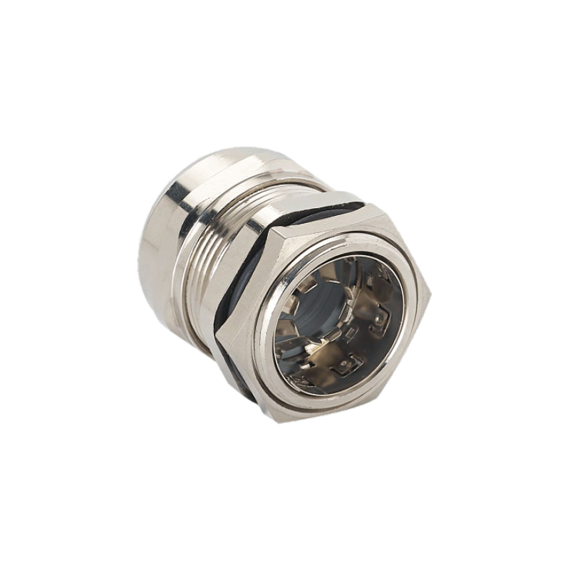
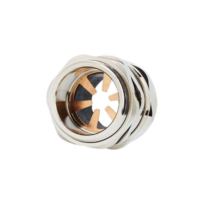
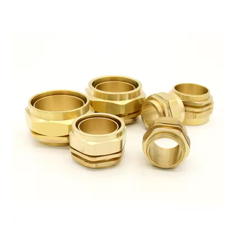
For VFD applications, brass or stainless steel EMC cable glands provide the best combination of electromagnetic shielding, durability, and environmental protection. The metallic construction ensures continuous shielding while offering superior mechanical strength compared to plastic alternatives.
EMC Cable Glands for VFD Systems
EMC cable glands are specifically designed for applications where electromagnetic compatibility is critical:
| Merkmal | Nutzen Sie | Anmeldung |
|---|---|---|
| 360° Shielding | Complete EMI containment | VFD control panels |
| Brass/SS Construction | Korrosionsbeständigkeit | Installationen im Freien |
| Federbelastete Kontakte | Reliable shield connection | Umgebungen mit hohen Vibrationen |
| IP68 Rating | Complete moisture protection | Abwaschbereiche |
I remember working with Hassan, who operates a chemical processing facility in Houston. His facility required explosion-proof ratings in addition to EMC protection. We provided ATEX-certified stainless steel EMC cable glands that met both his safety and electromagnetic compatibility requirements. The installation has been running flawlessly for three years without a single EMC-related issue.
Überlegungen zu gepanzerten Kabeln
When using armored cables with VFDs, the cable gland must provide proper termination for both the armor and the cable shield:
- Double-sealed design prevents moisture ingress at both armor and cable levels
- Armor clamping provides mechanical strain relief
- Durchgängigkeit der Abschirmung maintains EMC protection through the armor connection
How Do You Size Cable Glands for VFD Installations?
Proper sizing ensures reliable sealing, strain relief, and long-term performance while accommodating cable expansion under load.
Cable gland sizing for VFD applications requires considering the cable outer diameter plus 15-20% tolerance for thermal expansion and shield termination requirements. This additional clearance is crucial because VFD cables often carry higher currents that generate more heat than standard power cables.
Sizing Methodology
Follow this systematic approach for accurate sizing:
- Measure cable outer diameter including any outer sheath or armor
- Add thermal expansion allowance (typically 10-15% for VFD cables)
- Consider shield termination space (additional 5% for EMC glands)
- Select appropriate thread size based on panel thickness and space constraints
Common Sizing Mistakes
From my experience, these are the most frequent sizing errors I encounter:
- Undersizing for cost savings – leads to poor sealing and strain relief
- Ignoring thermal expansion – causes seal failure under load
- Overlooking shield requirements – compromises EMC performance
- Wrong thread selection – creates installation difficulties
At Bepto, we provide detailed sizing charts and technical support to help engineers select the optimal cable gland size for their specific VFD installation requirements.
Welche Umweltfaktoren sollten Sie berücksichtigen?
Environmental conditions significantly impact cable gland selection and long-term performance in motor applications.
Key environmental factors include temperature extremes, chemical exposure, vibration levels, and ingress protection requirements. Each factor influences material selection, sealing design, and installation methods.
Überlegungen zur Temperatur
VFD and motor installations often experience significant temperature variations:
- Betriebsbereich: -40°C to +100°C for most industrial applications
- Auswahl des Materials: EPDM seals for high-temperature applications
- Thermisches Zyklieren: Repeated expansion/contraction affects seal integrity
- Heat dissipation: Metallic glands provide better heat transfer than plastic
Chemische Beständigkeit
Industrial environments may expose cable glands to various chemicals:
- Konstruktion aus rostfreiem Stahl for corrosive environments
- Viton seals für chemische Beständigkeit
- Schützende Beschichtungen for specific chemical exposures
- Regelmäßige Inspektionstermine for early problem detection
Vibration und mechanische Belastung
Motor installations generate significant vibration that can affect cable gland performance:
- Konstruktion der Zugentlastung prevents cable fatigue
- Locking mechanisms prevent loosening
- Flexible Abdichtung accommodates movement
- Robuste Konstruktion withstands mechanical stress
Schlussfolgerung
Selecting the right cable glands for VFD and motor termination requires careful consideration of electromagnetic compatibility, environmental conditions, and mechanical requirements. The investment in quality EMC cable glands pays dividends through improved system reliability, reduced maintenance costs, and compliance with electromagnetic compatibility standards. At Bepto, we’re committed to helping engineers make informed decisions that ensure long-term success in their motor drive installations.
FAQ
Q: What’s the difference between EMC cable glands and regular cable glands for VFD applications?
A: EMC cable glands provide 360-degree electromagnetic shielding through metallic construction and continuous electrical bonding, while regular cable glands only offer basic sealing. This shielding is essential for VFD applications to prevent electromagnetic interference and ensure compliance with EMC standards.
Q: Can I use plastic cable glands for VFD motor connections?
A: Plastic cable glands should be avoided for VFD applications because they cannot provide the electromagnetic shielding required to contain VFD-generated interference. Metal EMC cable glands are necessary to maintain proper electromagnetic compatibility and prevent system disruptions.
Q: How do I determine the correct IP rating for motor cable glands?
A: Select IP rating based on your environment: IP54 for indoor dry locations, IP65 for outdoor or washdown areas, and IP68 for submersible applications. Motor installations typically require minimum IP65 protection due to moisture, dust, and cleaning requirements in industrial settings.
Q: What thread types work best for VFD panel installations?
A: Metric threads (M12, M16, M20, M25) are most common in industrial VFD panels, though NPT threads may be required for North American installations. Choose thread type based on your panel specifications and local electrical codes for proper fit and compliance.
Q: How often should I inspect cable glands in motor applications?
A: Inspect cable glands quarterly in high-vibration motor applications and annually in standard installations. Check for loose connections, seal integrity, corrosion, and proper strain relief. Early detection prevents costly failures and maintains system reliability.
-
Learn the operating principle of VFDs and how they control motor speed. ↩
-
Understand the definition of EMI and how it disrupts electronic circuits. ↩
-
Explore the principles of electromagnetic compatibility (EMC) shielding and how it contains interference. ↩
-
Learn the definition of electrical continuity and its importance in creating a grounding path. ↩
