
Introduction
Molecular contamination from outgassing cable gland materials can destroy semiconductor wafers, compromise optical coatings, and contaminate ultra-high vacuum systems, causing millions in product losses and research delays when volatile organic compounds exceed critical cleanliness thresholds in sensitive manufacturing environments.
PTFE and PEEK cable gland materials demonstrate the lowest outgassing rates at <1×10⁻⁸ torr·L/s·cm² for vacuum applications, while specially formulated low-outgassing elastomers and metal components provide reliable sealing performance in cleanroom environments requiring ISO Class 1-5 cleanliness standards1.
After a decade of working with semiconductor fabs, aerospace manufacturers, and research institutions, I’ve learned that selecting the right low-outgassing cable gland materials isn’t just about meeting specifications—it’s about preventing contamination that can shut down entire production lines or compromise critical research projects.
Table of Contents
- What Causes Outgassing in Cable Gland Materials?
- Which Materials Provide the Lowest Outgassing Rates?
- How Do You Test and Measure Outgassing Performance?
- What Are the Requirements for Different Cleanroom Classifications?
- How Do You Select Cable Glands for Ultra-High Vacuum Applications?
- FAQs About Low-Outgassing Cable Gland Materials
What Causes Outgassing in Cable Gland Materials?
Understanding outgassing mechanisms is essential for selecting appropriate materials for cleanroom and vacuum applications.
Outgassing2 occurs when volatile organic compounds, plasticizers, and absorbed moisture migrate from cable gland materials into the surrounding environment, with emission rates increasing exponentially with temperature and decreasing pressure, creating molecular contamination that can compromise sensitive processes and equipment.
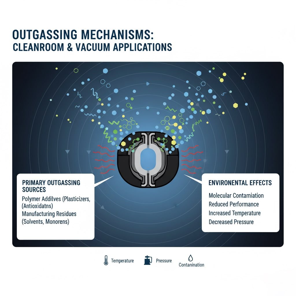
Primary Outgassing Sources
Polymer Additives:
- Plasticizers improve flexibility but increase outgassing
- Antioxidants prevent degradation but can volatilize
- Processing aids and mold release agents
- Colorants and UV stabilizers contribute to emissions
Manufacturing Residues:
- Solvent residues from processing
- Unreacted monomers and oligomers
- Catalyst and initiator remnants
- Surface contamination from handling
I worked with Dr. Sarah Chen, a process engineer at a semiconductor fab in Silicon Valley, where standard nylon cable glands were causing particle contamination in their Class 1 cleanroom, leading to 15% yield loss on advanced logic chips.
Environmental Factors
Temperature Effects:
- Outgassing rate doubles every 10°C increase
- Thermal cycling accelerates volatile release
- High-temperature bakeout reduces long-term emissions
- Activation energy determines temperature sensitivity
Pressure Influence:
- Lower pressure increases driving force for outgassing
- Vacuum conditions prevent reabsorption
- Molecular flow regime affects mass transfer
- Pumping speed impacts equilibrium concentrations
Time Dependencies:
- Initial burst of high outgassing rates
- Gradual decline following power law
- Long-term steady-state emissions
- Aging effects on material properties
Dr. Chen’s fab required a complete material evaluation and selection process to identify cable gland materials with outgassing rates below 1×10⁻⁹ torr·L/s·cm² to maintain their critical cleanliness requirements.
Contamination Mechanisms
Surface Adsorption:
- Volatile compounds condense on cold surfaces
- Molecular layers build up over time
- Desorption creates secondary contamination
- Critical surface temperatures affect condensation
Chemical Reactions:
- Outgassed species react with process chemicals
- Catalytic effects on sensitive surfaces
- Corrosion and etching of optical components
- Formation of non-volatile residues
Particulate Generation:
- Polymer degradation creates particles
- Thermal stress causes material shedding
- Mechanical wear generates debris
- Electrostatic attraction concentrates particles
Which Materials Provide the Lowest Outgassing Rates?
Material selection is critical for achieving ultra-low outgassing performance in demanding applications.
PTFE, PEEK, and PPS polymers offer outgassing rates below 1×10⁻⁸ torr·L/s·cm², while specially processed EPDM and FKM elastomers provide sealing capability with rates below 1×10⁻⁷ torr·L/s·cm², and electropolished stainless steel components contribute minimal contamination in vacuum systems.
Polymer Material Performance
Ultra-Low Outgassing Polymers:
| Material | Outgassing Rate (torr·L/s·cm²) | Temperature Limit | Key Advantages | Applications |
|---|---|---|---|---|
| PTFE | <1×10⁻⁹ | 260°C | Chemical inert, low friction | UHV, semiconductor |
| PEEK | <5×10⁻⁹ | 250°C | High strength, radiation resistant | Aerospace, research |
| PPS | <1×10⁻⁸ | 220°C | Good chemical resistance | Automotive, electronics |
| PI (Polyimide) | <2×10⁻⁸ | 300°C | High temperature stability | Space applications |
Elastomer Options:
- Low-outgassing EPDM: <1×10⁻⁷ torr·L/s·cm²
- Specially processed FKM: <5×10⁻⁷ torr·L/s·cm²
- Perfluoroelastomer: <1×10⁻⁸ torr·L/s·cm²
- Silicone (low-outgassing grade): <1×10⁻⁶ torr·L/s·cm²
Metal Component Considerations
Stainless Steel Grades:
- 316L electropolished: <1×10⁻¹⁰ torr·L/s·cm²
- 304 standard finish: <1×10⁻⁹ torr·L/s·cm²
- Passivation treatment reduces outgassing
- Surface roughness affects emission rates
Alternative Metals:
- Aluminum alloys with anodized finish
- Titanium for corrosive environments
- Inconel for high-temperature applications
- Copper for specific electrical requirements
I remember working with Hans, a vacuum systems engineer at a research facility in Munich, Germany, where they needed cable glands for a particle accelerator beamline requiring ultra-high vacuum conditions below 1×10⁻¹¹ torr.
Hans’s application required all-metal cable glands with PTFE insulation and specially processed seals to achieve the required vacuum levels without compromising electrical performance.
Processing and Treatment Effects
Surface Preparation:
- Electropolishing reduces surface area
- Chemical cleaning removes contaminants
- Passivation treatments improve stability
- Controlled atmosphere processing
Thermal Conditioning:
- Vacuum bakeout at elevated temperature
- Removes volatile compounds and moisture
- Accelerated aging for stability
- Quality control verification testing
Quality Assurance:
- Material certification and traceability
- Batch testing for outgassing performance
- Statistical process control
- Contamination-free packaging and handling
How Do You Test and Measure Outgassing Performance?
Standardized testing methods ensure reliable measurement of outgassing rates for material qualification.
ASTM E5953 and NASA SP-R-0022A provide standardized test methods for measuring total mass loss (TML) and collected volatile condensable materials (CVCM), with acceptance criteria of TML <1.0% and CVCM <0.1% for spacecraft applications, while ASTM F1408 measures outgassing rates for vacuum applications.
Standard Test Methods
ASTM E595 Screening Test:
- 24-hour exposure at 125°C in vacuum
- Measures total mass loss (TML)
- Collects volatile condensable materials (CVCM)
- Pass/fail criteria for space applications
- Widely accepted industry standard
ASTM F1408 Rate Measurement:
- Continuous monitoring of outgassing rate
- Temperature and time dependence characterization
- Suitable for vacuum system design
- Provides kinetic data for modeling
Custom Test Protocols:
- Application-specific temperature profiles
- Extended duration testing
- Chemical analysis of outgassed species
- Contamination sensitivity evaluation
Testing Equipment and Procedures
Vacuum Systems:
- Ultra-high vacuum test chambers
- Residual gas analyzers (RGA)
- Quadrupole mass spectrometers
- Pressure measurement systems
Sample Preparation:
- Controlled cutting and handling
- Surface area measurement
- Pre-conditioning procedures
- Contamination prevention protocols
Data Analysis:
- Outgassing rate calculations
- Statistical analysis of results
- Arrhenius modeling for temperature effects
- Lifetime predictions and extrapolation
Quality Control Applications
Material Qualification:
- Supplier certification requirements
- Batch-to-batch consistency verification
- Process validation testing
- Long-term stability assessment
Production Monitoring:
- Statistical sampling plans
- Trend analysis and control charts
- Non-conformance investigation
- Continuous improvement programs
At Bepto, we maintain partnerships with certified testing laboratories to provide comprehensive outgassing characterization for all our cleanroom and vacuum-compatible cable gland products.
What Are the Requirements for Different Cleanroom Classifications?
Cleanroom classifications dictate specific material requirements and contamination control measures.
ISO Class 1 cleanrooms require cable gland materials with particle generation <0.1 particles/m³ >0.1μm and molecular contamination <1×10⁻⁹ g/cm²·min, while Class 5 environments allow higher limits of <3520 particles/m³ >0.5μm and molecular contamination <1×10⁻⁷ g/cm²·min for semiconductor and pharmaceutical manufacturing.
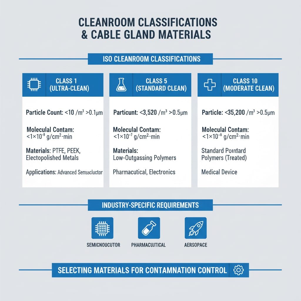
ISO Cleanroom Classifications
Class 1 Requirements (Ultra-Clean):
- Particle count: <10 particles/m³ >0.1μm
- Molecular contamination: <1×10⁻⁹ g/cm²·min
- Cable gland materials: PTFE, PEEK, electropolished metals
- Applications: Advanced semiconductor lithography
Class 5 Requirements (Standard Clean):
- Particle count: <3,520 particles/m³ >0.5μm
- Molecular contamination: <1×10⁻⁷ g/cm²·min
- Cable gland materials: Low-outgassing polymers, treated metals
- Applications: Pharmaceutical manufacturing, electronics assembly
Class 10 Requirements (Moderate Clean):
- Particle count: <35,200 particles/m³ >0.5μm
- Molecular contamination: <1×10⁻⁶ g/cm²·min
- Cable gland materials: Standard polymers with treatments
- Applications: Medical device manufacturing
Industry-Specific Requirements
Semiconductor Manufacturing:
- Airborne molecular contamination (AMC) limits
- Metal ion contamination <1×10¹⁰ atoms/cm²
- Organic contamination <1×10¹⁵ molecules/cm²
- Particle size distribution requirements
Pharmaceutical Production:
- USP Class standards for sterile manufacturing
- Bioburden and endotoxin limits
- Chemical compatibility with cleaning agents
- Validation and documentation requirements
Aerospace and Defense:
- MIL-STD-1246 cleanliness levels
- Spacecraft contamination control requirements
- Thermal vacuum stability testing
- Long-term mission reliability
I worked with Ahmed, who manages a pharmaceutical manufacturing facility in Dubai, UAE, where they needed cable glands for sterile filling operations requiring ISO Class 5 conditions with additional biocompatibility requirements.
Ahmed’s facility required extensive material testing and validation to ensure cable glands met both cleanliness and regulatory requirements for pharmaceutical production.
Installation and Maintenance Considerations
Installation Protocols:
- Cleanroom-compatible packaging
- Contamination-free handling procedures
- Pre-installation cleaning and inspection
- Documentation and traceability requirements
Maintenance Requirements:
- Periodic cleaning and inspection schedules
- Replacement criteria and procedures
- Contamination monitoring programs
- Performance verification testing
Quality Assurance:
- Material certification and documentation
- Installation qualification (IQ) procedures
- Operational qualification (OQ) testing
- Performance qualification (PQ) validation
How Do You Select Cable Glands for Ultra-High Vacuum Applications?
Ultra-high vacuum systems require specialized cable gland designs and materials to achieve pressures below 1×10⁻⁹ torr.
UHV cable glands must use all-metal construction with PTFE or ceramic insulation, achieving leak rates <1×10⁻¹⁰ atm·cc/s helium, while maintaining electrical performance and providing reliable sealing through multiple thermal cycles from -196°C to +450°C bakeout temperatures.
UHV Design Requirements
Vacuum Performance:
- Base pressure: <1×10⁻⁹ torr achievable
- Leak rate: <1×10⁻¹⁰ atm·cc/s helium
- Outgassing rate: <1×10⁻¹² torr·L/s·cm²
- Thermal cycling capability: -196°C to +450°C
Material Selection:
- 316L stainless steel construction
- PTFE or ceramic electrical insulation
- Metal-to-metal sealing interfaces
- Electropolished surface finishes
Design Features:
- Conflat (CF) flanges for UHV compatibility
- Knife-edge sealing with copper gaskets
- Minimal internal volume and surface area
- Bakeable to 450°C for conditioning
Electrical Performance Considerations
Insulation Requirements:
- High voltage breakdown strength
- Low leakage current <1 nA
- Temperature stability over operating range
- Radiation resistance for specific applications
Conductor Materials:
- Oxygen-free copper for low outgassing
- Silver or gold plating for corrosion resistance
- Controlled thermal expansion matching
- Mechanical stress relief design
Shielding and EMC:
- Continuous shielding path through feedthrough
- Low impedance ground connections
- Minimal electromagnetic interference
- Compatibility with sensitive measurements
Application Examples
Particle Accelerators:
- Ultra-high vacuum requirements
- High radiation environments
- Precise electrical performance
- Long-term reliability needs
Surface Analysis Equipment:
- Electron spectroscopy systems
- Ion beam analysis tools
- Scanning probe microscopes
- Mass spectrometry applications
Space Simulation Chambers:
- Thermal vacuum testing
- Contamination-sensitive payloads
- Long-duration missions
- Extreme temperature cycling
At Bepto, we offer specialized UHV cable gland solutions designed and tested specifically for ultra-high vacuum applications, ensuring reliable performance in the most demanding research and industrial environments.
Conclusion
Selecting the right cable gland materials for cleanroom and vacuum applications is critical for preventing contamination that can compromise sensitive processes and equipment. PTFE and PEEK offer the lowest outgassing rates for ultra-clean environments, while specially processed elastomers provide necessary sealing performance. Understanding cleanroom classifications and vacuum requirements helps ensure proper material selection, with ISO Class 1 demanding the most stringent materials and UHV applications requiring all-metal construction. Standardized testing methods like ASTM E595 provide reliable qualification data, while proper installation and maintenance procedures maintain long-term performance. At Bepto, we combine extensive materials expertise with comprehensive testing capabilities to deliver cable gland solutions that meet the most demanding cleanliness and vacuum requirements. Remember, investing in proper low-outgassing materials today prevents costly contamination issues and production delays tomorrow! 😉
FAQs About Low-Outgassing Cable Gland Materials
Q: What outgassing rate do I need for cleanroom cable glands?
A: ISO Class 1 cleanrooms require outgassing rates below 1×10⁻⁹ g/cm²·min, while Class 5 environments allow up to 1×10⁻⁷ g/cm²·min. PTFE and PEEK materials typically achieve these requirements with proper processing and handling.
Q: Can standard cable glands be used in vacuum applications?
A: Standard cable glands with conventional elastomers and untreated surfaces are unsuitable for vacuum applications due to high outgassing rates. Specialized low-outgassing materials and vacuum-compatible designs are required for pressures below 1×10⁻⁶ torr.
Q: How do I test cable gland materials for outgassing performance?
A: Use ASTM E595 for screening tests measuring total mass loss (TML) and collected volatile condensable materials (CVCM). For vacuum applications, ASTM F1408 provides outgassing rate measurements. Accept materials with TML <1.0% and CVCM <0.1% for critical applications.
Q: What’s the difference between cleanroom and vacuum cable gland requirements?
A: Cleanroom applications focus on particle generation and molecular contamination at atmospheric pressure, while vacuum applications emphasize outgassing rates and leak tightness at reduced pressure. Vacuum systems typically require more stringent material specifications and all-metal construction.
Q: How long do low-outgassing cable glands maintain their performance?
A: Properly selected and installed low-outgassing cable glands maintain performance for 5-10 years in cleanroom applications and 10-20 years in vacuum systems. Regular monitoring and maintenance according to facility protocols ensure continued compliance with cleanliness requirements.
-
Review the official ISO 14644-1 standard that defines the classification of air cleanliness by particle concentration in cleanrooms. ↩
-
Understand the scientific principles of outgassing and why it is a critical factor in high-vacuum and cleanroom environments. ↩
-
Access the details of the ASTM E595 standard, the primary test method for measuring outgassing properties of materials in a vacuum. ↩
