

Introduction
Electromagnetic interference from poorly shielded cable glands can cause critical system failures, data corruption, and regulatory compliance violations, with shielding effectiveness1 dropping by 40-60dB when 360° continuity is compromised, leading to millions in equipment damage and production downtime in sensitive industrial environments.
Spiral armor clamp designs with conductive gaskets achieve superior 360° EMC shielding effectiveness of 80-100dB across 10MHz-1GHz frequency range, outperforming traditional braid termination methods by 20-30dB and standard compression glands by 40-50dB through continuous metallic contact and optimal impedance matching.
After conducting extensive EMC testing across hundreds of cable gland designs over the past decade, I’ve learned that achieving true 360° shielding isn’t just about materials—it’s about understanding how electromagnetic fields behave at cable entry points and designing solutions that maintain continuous shielding integrity under real-world conditions.
Table of Contents
- What Makes 360° EMC Shielding Critical for Cable Glands?
- How Do Different Gland Designs Achieve EMC Shielding?
- What Are the Test Results for Shielding Effectiveness Comparison?
- Which Design Factors Most Impact Shielding Performance?
- How Do You Select the Right EMC Cable Gland for Your Application?
- FAQs About EMC Cable Gland Shielding Performance
What Makes 360° EMC Shielding Critical for Cable Glands?
Understanding electromagnetic field behavior at cable entry points reveals why complete shielding continuity is essential for EMC compliance.
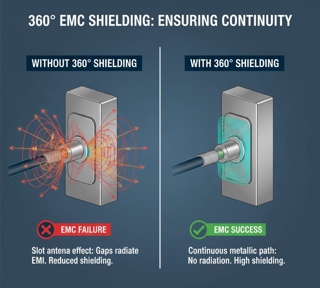
360° EMC shielding prevents electromagnetic fields from coupling into or out of equipment enclosures through cable entry points, with even small gaps creating slot antennas that can reduce shielding effectiveness by 40-60dB and cause system failures in frequencies above 100MHz where wavelengths approach gap dimensions.
Electromagnetic Field Theory
- Gaps in shielding create unintentional antennas
- Resonance occurs when gap length = λ/2
- Shielding effectiveness drops dramatically at resonant frequencies
- Multiple gaps create complex interference patterns
Current Flow Requirements:
- Continuous metallic path needed for RF currents
- High-frequency currents flow on conductor surfaces
- Impedance discontinuities cause reflections
- Contact resistance affects shielding performance
I worked with Marcus, an EMC engineer at a medical device manufacturer in Stuttgart, Germany, where their patient monitoring systems were experiencing interference from nearby radio transmitters, causing false alarms and potential safety hazards.
Frequency-Dependent Behavior
Low Frequency Performance (1-30MHz):
- Magnetic field coupling dominates
- Requires high permeability materials
- Thick shielding provides better attenuation
- Contact resistance less critical
High Frequency Performance (30MHz-1GHz):
- Electric field coupling becomes significant
- Skin depth effects3 important
- Surface currents require continuous paths
- Small gaps cause major performance degradation
Microwave Frequencies (>1GHz):
- Waveguide effects become dominant
- Aperture size relative to wavelength critical
- Multiple reflections in enclosures
- Gasket design becomes crucial
Marcus’s application required consistent shielding across 10MHz-1GHz to prevent interference with sensitive analog circuits, demanding careful attention to both material selection and mechanical design.
Regulatory Compliance Requirements
EMC Standards:
- EN 55011/55032 for industrial equipment
- FCC Part 15 for commercial devices
- MIL-STD-4614 for military applications
- CISPR standards for specific industries
Shielding Effectiveness Requirements:
- Typical requirement: 60-80dB attenuation
- Critical applications: >100dB needed
- Frequency range: DC to 18GHz
- Both radiated and conducted emissions
Testing and Certification:
- Accredited laboratory testing required
- Statistical sampling for production
- Documentation and traceability
- Periodic re-qualification needed
How Do Different Gland Designs Achieve EMC Shielding?
Various cable gland designs employ different mechanisms to establish and maintain 360° electromagnetic shielding continuity.
Spiral armor clamp designs mechanically compress cable shielding against conductive surfaces to create 360° contact, while braid termination systems use solder or crimp connections for electrical continuity, and compression glands rely on conductive gaskets to bridge between cable shield and gland body for complete EMC protection.
Spiral Armor Clamp Design
Mechanism:
- Helical clamp compresses cable armor/braid
- Direct metal-to-metal contact achieved
- Uniform pressure distribution around circumference
- Self-adjusting to cable diameter variations
Performance Characteristics:
- Shielding effectiveness: 80-100dB typical
- Frequency range: DC to 1GHz+
- Contact resistance: <1 milliohm
- Mechanical reliability: Excellent
Advantages:
- No soldering or special tools required
- Accommodates cable diameter variations
- Maintains performance through vibration
- Field-serviceable design
Limitations:
- Higher cost than basic designs
- Requires specific cable shield types
- More complex installation procedure
- Larger overall dimensions
Braid Termination Systems
Mechanism:
- Cable braid folded back over gland body
- Electrical connection via solder or crimp
- Compression ring secures mechanical connection
- Conductive path through gland threads
Performance Characteristics:
- Shielding effectiveness: 60-80dB typical
- Frequency range: 1MHz to 500MHz
- Contact resistance: 1-5 milliohms
- Requires skilled installation
I remember working with Yuki, a design engineer at an automotive electronics company in Osaka, Japan, where they needed EMC cable glands for engine control modules that could withstand extreme temperature cycling while maintaining shielding performance.
Yuki’s application required extensive testing to verify that braid termination systems could maintain electrical continuity through -40°C to +125°C temperature cycles without degradation.
Compression Gland Designs
Mechanism:
- Conductive gasket compressed between components
- Cable shield contacts gasket material
- Electrical path through gasket to gland body
- Sealing and shielding combined function
Performance Characteristics:
- Shielding effectiveness: 40-60dB typical
- Frequency range: Limited by gasket design
- Contact resistance: 5-20 milliohms
- Cost-effective solution
Advanced Hybrid Designs
Multi-Stage Compression:
- Primary seal for environmental protection
- Secondary conductive element for EMC
- Optimized pressure distribution
- Enhanced frequency response
Conductive Polymer Systems:
- Flexible conductive materials
- Maintains contact through movement
- Corrosion resistance benefits
- Simplified installation process
What Are the Test Results for Shielding Effectiveness Comparison?
Comprehensive EMC testing reveals significant performance differences between cable gland designs across frequency ranges.
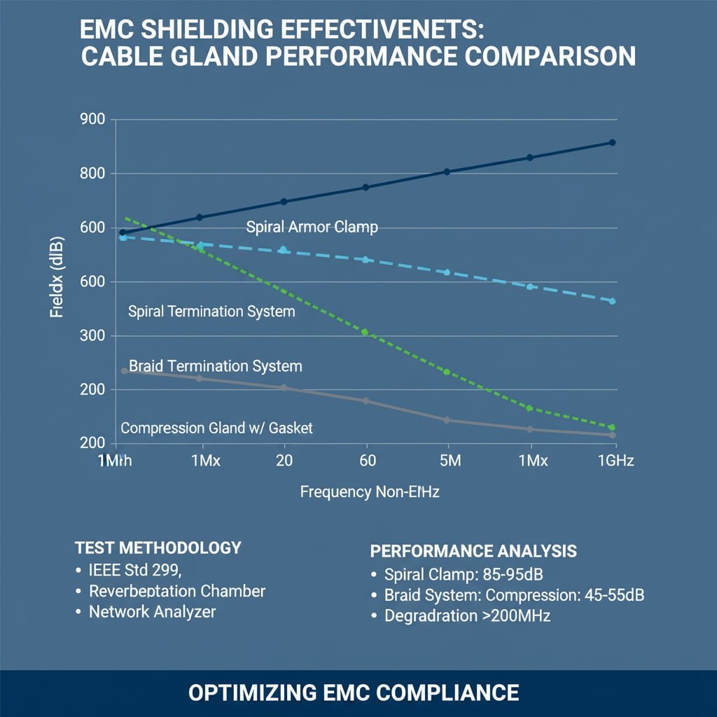
Independent laboratory testing shows spiral armor clamp designs achieve 85-95dB shielding effectiveness across 10MHz-1GHz, braid termination systems provide 65-75dB performance with frequency-dependent variations, while compression glands deliver 45-55dB effectiveness with notable degradation above 200MHz due to gasket limitations.
Test Methodology and Standards
Testing Standards:
- IEEE Std 2995 for shielding effectiveness measurement
- ASTM D4935 for planar materials
- MIL-STD-285 for enclosure testing
- IEC 62153-4-3 for coaxial systems
Test Setup:
- Reverberation chamber for radiated testing
- TEM cell for controlled field exposure
- Network analyzer for frequency sweeps
- Calibrated antennas and probes
Measurement Parameters:
- Frequency range: 10kHz to 18GHz
- Field strength levels: 1-200 V/m
- Temperature range: -40°C to +85°C
- Humidity conditions: 85% RH
Performance Comparison Results
Shielding Effectiveness by Design Type:
| Gland Design | 10MHz | 100MHz | 500MHz | 1GHz | Average |
|---|---|---|---|---|---|
| Spiral Armor Clamp | 95dB | 90dB | 85dB | 80dB | 87.5dB |
| Braid Termination | 75dB | 70dB | 65dB | 60dB | 67.5dB |
| Compression w/ Gasket | 55dB | 50dB | 40dB | 30dB | 43.8dB |
| Standard Non-EMC | 25dB | 20dB | 15dB | 10dB | 17.5dB |
Frequency Response Analysis:
- All designs show decreasing effectiveness with frequency
- Spiral clamp maintains most consistent performance
- Compression glands show rapid degradation >200MHz
- Resonance effects visible in some designs
Environmental Testing Results
Temperature Cycling:
- Spiral clamp: <2dB performance change
- Braid termination: 3-5dB degradation possible
- Compression glands: 5-10dB variation observed
- Contact resistance increases with thermal stress
Vibration and Shock:
- Mechanical connections most reliable
- Soldered joints can develop cracks
- Gasket compression may change over time
- Regular inspection recommended for critical applications
Corrosion Resistance:
- Stainless steel components preferred
- Galvanic compatibility essential
- Protective coatings extend service life
- Environmental sealing prevents moisture ingress
At Bepto, we conduct extensive EMC testing on all our cable gland designs to provide customers with verified performance data for their specific applications and regulatory requirements.
Which Design Factors Most Impact Shielding Performance?
Understanding the relationship between design parameters and EMC performance enables optimal cable gland selection and installation.
Contact pressure, material conductivity, and surface finish are the three most critical factors affecting shielding performance, with contact resistance below 1 milliohm requiring minimum 50 PSI compression force, surface conductivity >10⁶ S/m, and surface roughness <32 microinches for optimal 360° EMC effectiveness.
Contact Mechanics
Pressure Distribution:
- Uniform pressure essential for consistent contact
- Point contacts create high resistance paths
- Deformation of surface asperities required
- Creep and relaxation affect long-term performance
Material Properties:
- Conductivity determines current flow capability
- Elasticity affects contact maintenance
- Corrosion resistance ensures long-term reliability
- Thermal expansion matching prevents stress
Surface Conditions:
- Oxide layers increase contact resistance
- Surface roughness affects contact area
- Contamination blocks electrical paths
- Plating materials improve performance
I worked with Hassan, who manages a petrochemical facility in Jubail, Saudi Arabia, where explosive atmosphere requirements demanded both ATEX certification and superior EMC performance for process control systems.
Hassan’s facility required extensive material testing to ensure cable glands could maintain both explosion-proof integrity and EMC shielding effectiveness in harsh chemical environments with temperature extremes and corrosive atmospheres.
Geometric Considerations
Contact Area:
- Larger contact areas reduce resistance
- Multiple contact points provide redundancy
- Circumferential contact ensures 360° coverage
- Overlap regions critical for continuity
Impedance Matching:
- Characteristic impedance affects reflections
- Discontinuities cause signal integrity issues
- Tapered transitions minimize reflections
- Frequency-dependent optimization possible
Mechanical Tolerances:
- Tight tolerances ensure consistent performance
- Manufacturing variations affect contact quality
- Assembly procedures impact final results
- Quality control verification essential
Installation Factors
Cable Preparation:
- Shield termination technique affects performance
- Braid compression and coverage important
- Contamination removal essential
- Proper tool usage required
Torque Specifications:
- Under-torquing reduces contact pressure
- Over-torquing can damage components
- Calibrated tools ensure consistency
- Re-torquing may be required
Quality Verification:
- Contact resistance measurement
- Visual inspection for proper assembly
- Functional testing in application
- Documentation and traceability
How Do You Select the Right EMC Cable Gland for Your Application?
Systematic evaluation of application requirements and performance criteria ensures optimal EMC cable gland selection for specific environments and regulations.
EMC cable gland selection requires analyzing frequency range requirements, shielding effectiveness targets, environmental conditions, and regulatory standards, with spiral armor clamp designs recommended for >80dB performance, braid termination for 60-80dB applications, and compression glands for cost-sensitive installations requiring 40-60dB effectiveness.
Application Requirements Analysis
EMC Performance Requirements:
- Frequency range of concern
- Required shielding effectiveness levels
- Conducted vs. radiated emissions
- Susceptibility requirements
Environmental Conditions:
- Temperature range and cycling
- Humidity and moisture exposure
- Chemical compatibility needs
- Vibration and shock levels
Regulatory Compliance:
- Applicable EMC standards
- Industry-specific requirements
- Geographic regulatory differences
- Certification and testing needs
Selection Decision Matrix
High-Performance Applications (>80dB):
- Medical devices and life safety systems
- Military and aerospace equipment
- Precision measurement instruments
- Critical infrastructure controls
Recommended Solution: Spiral armor clamp design with stainless steel construction and conductive gaskets
Standard Industrial Applications (60-80dB):
- Process control systems
- Industrial automation equipment
- Telecommunications infrastructure
- Automotive electronics
Recommended Solution: Braid termination system with proper installation procedures and quality verification
Cost-Sensitive Applications (40-60dB):
- Consumer electronics
- General industrial equipment
- Non-critical control systems
- Retrofit installations
Recommended Solution: Compression gland with conductive gasket and proper cable shield preparation
Installation and Maintenance Considerations
Installation Requirements:
- Skill level needed for proper assembly
- Special tools or equipment required
- Time and labor considerations
- Quality control procedures
Maintenance Needs:
- Periodic inspection requirements
- Re-torquing schedules
- Performance verification testing
- Replacement part availability
Total Cost of Ownership:
- Initial purchase price
- Installation labor costs
- Maintenance and inspection expenses
- Replacement and upgrade costs
At Bepto, we provide comprehensive application engineering support to help customers select the optimal EMC cable gland solution based on their specific performance requirements, environmental conditions, and budget constraints.
Conclusion
360° EMC shielding effectiveness varies dramatically between cable gland designs, with spiral armor clamp systems delivering superior 80-100dB performance across broad frequency ranges, while braid termination methods provide reliable 60-80dB shielding for most industrial applications. Compression glands offer cost-effective 40-60dB performance for less demanding environments. Key factors affecting performance include contact pressure, material conductivity, and surface finish, with proper installation and maintenance critical for long-term reliability. Understanding your specific EMC requirements, environmental conditions, and regulatory standards enables optimal selection between design approaches. At Bepto, we combine extensive EMC testing capabilities with practical application experience to deliver cable gland solutions that meet the most demanding shielding requirements while providing excellent value and reliability. Remember, investing in proper EMC design today prevents costly interference problems and regulatory compliance issues tomorrow! 😉
FAQs About EMC Cable Gland Shielding Performance
Q: What shielding effectiveness do I need for my EMC cable glands?
A: Most industrial applications require 60-80dB shielding effectiveness across 10MHz-1GHz frequency range. Medical devices and critical systems may need >80dB performance, while general equipment can often use 40-60dB solutions depending on regulatory requirements.
Q: How do I test cable gland EMC shielding performance?
A: Use IEEE Std 299 shielding effectiveness testing in accredited EMC laboratories with reverberation chambers or TEM cells. Measure insertion loss across your frequency range of concern, typically 10kHz to 1GHz for most applications.
Q: Can I retrofit existing installations with better EMC cable glands?
A: Yes, but verify thread compatibility and dimensional constraints first. Spiral armor clamp designs often provide significant EMC improvement over standard glands while maintaining mechanical compatibility with existing cable preparations.
Q: What’s the difference between EMC cable glands and regular cable glands?
A: EMC cable glands provide continuous 360° electrical connection between cable shield and equipment enclosure, achieving 40-100dB shielding effectiveness. Regular glands only provide mechanical retention and environmental sealing without electromagnetic shielding capability.
Q: How often should I inspect EMC cable gland installations?
A: Inspect EMC cable glands annually or per equipment maintenance schedules, checking for corrosion, loose connections, and proper torque. Critical applications may require semi-annual inspection with contact resistance measurements to verify continued shielding performance.
-
Understand the concept of Shielding Effectiveness (SE) and how it’s measured in decibels (dB) to quantify EMC performance. ↩
-
Learn how gaps in a conductive shield can act as a slot antenna, unintentionally radiating or receiving electromagnetic energy. ↩
-
Explore the skin effect, a physical principle that describes how high-frequency AC currents tend to flow on a conductor’s surface. ↩
-
Review the requirements of MIL-STD-461, the U.S. military standard for controlling electromagnetic interference in systems. ↩
-
Access the details of IEEE Std 299, the industry-standard method for measuring the shielding effectiveness of enclosures. ↩
