
Offshore installations face some of the harshest environments on Earth, where a single cable gland failure can trigger catastrophic fires, explosions, or complete system shutdowns. Traditional cable glands simply aren’t enough when dealing with hydrocarbon vapors, extreme weather, and the constant threat of fire in oil and gas operations.
Deluge Protection (DTS01) is a specialized fire suppression system that provides automatic water spray protection for cable glands in offshore hazardous areas, meeting DNV GL1 and API2 standards for enhanced safety in explosive atmospheres. This system activates during fire emergencies to cool equipment and prevent flame propagation through cable penetrations.
Having worked with major offshore operators across the North Sea, Middle East, and Asia-Pacific regions, I’ve witnessed firsthand how proper deluge protection can mean the difference between a contained incident and a platform-wide emergency. Let me share what every offshore engineer needs to know about this critical safety system.
Table of Contents
- What is DTS01 Deluge Protection System?
- Why Do Offshore Cable Glands Require Special Protection?
- How Does Deluge Protection Work with Cable Glands?
- What Are the Key Design Requirements?
- How to Select Compatible Cable Glands?
- FAQs About Deluge Protection for Cable Glands
What is DTS01 Deluge Protection System?
DTS01 (Deluge Type System 01) is an automatic fire suppression system specifically designed for offshore installations, providing high-volume water spray protection for electrical equipment and cable penetrations in hazardous areas.
The system represents a critical safety barrier in offshore risk management, designed to operate in the most challenging marine environments where traditional fire suppression methods prove inadequate.
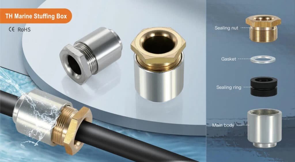
Core System Components
Detection Network: Advanced heat and flame detection systems monitor hazardous areas continuously. These typically include linear heat detection cables3, UV/IR flame detectors4, and temperature sensors strategically positioned around cable gland installations.
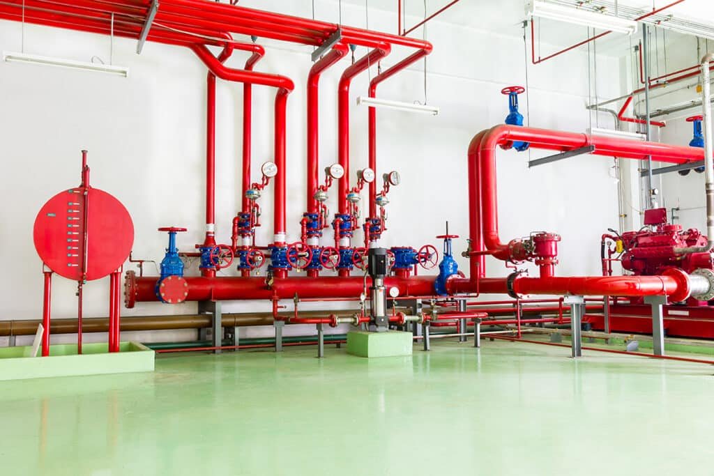
Water Distribution: High-capacity pumps deliver seawater through corrosion-resistant piping networks. The system maintains constant pressure and flow rates capable of delivering 10-20 liters per minute per square meter of protected area.
Activation Mechanism: Automatic activation occurs through redundant control systems, typically requiring confirmation from multiple detection points to prevent false alarms while ensuring rapid response during genuine emergencies.
Drainage Systems: Effective water drainage prevents accumulation that could damage electrical equipment or create additional hazards during system operation.
I remember working with Hassan, a safety manager for a major oil platform in the Persian Gulf. His facility experienced a small electrical fire in a cable junction area. The DTS01 system activated within 45 seconds, containing the fire before it could spread to adjacent hydrocarbon processing equipment. Without this protection, the incident could have escalated into a major emergency requiring platform evacuation. 😊
Regulatory Framework
DNV GL Standards: The system must comply with DNV-OS-D301 for fire protection systems and DNV-RP-G101 for risk-based inspection planning.
API Requirements: API RP 14C provides guidelines for offshore safety systems, including deluge protection design criteria and performance standards.
International Standards: The IEC 618925 series covers electrical installations in mobile and fixed offshore units, specifying protection requirements for cable systems.
Why Do Offshore Cable Glands Require Special Protection?
Offshore cable glands face unique hazards including hydrocarbon vapor exposure, extreme weather conditions, and the potential for rapid fire spread in confined spaces—making specialized protection systems essential for personnel safety and asset protection.
The offshore environment creates a perfect storm of conditions that can turn minor electrical faults into major disasters. Understanding these risks is crucial for proper protection system design.
Unique Offshore Hazards
| Hazard Type | Risk Level | Potential Consequences | Protection Requirements |
|---|---|---|---|
| Hydrocarbon Vapors | Extreme | Explosion, flash fire | Ex-rated equipment + deluge |
| Salt Spray Corrosion | High | Seal degradation, arcing | Stainless steel + protective coatings |
| Extreme Weather | High | Physical damage, flooding | Enhanced IP ratings + structural protection |
| Confined Spaces | Medium | Rapid fire spread | Active suppression systems |
Hydrocarbon Environment: Oil and gas platforms contain numerous sources of flammable vapors. A simple electrical arc from a damaged cable gland can ignite these vapors, creating flash fires or explosions. Deluge protection provides immediate cooling and vapor suppression.
Corrosive Atmosphere: Constant salt spray accelerates corrosion of metal components, potentially compromising explosion-proof enclosures and cable gland sealing systems. The combination of corrosion and electrical faults significantly increases fire risk.
Weather Extremes: Offshore installations face hurricanes, extreme temperatures, and massive waves. These conditions can damage cable glands, creating entry points for moisture and potential ignition sources.
Escape Route Limitations: Unlike onshore facilities, offshore platforms have limited evacuation options. Fire suppression systems must contain incidents quickly to prevent personnel from becoming trapped.
Fire Propagation Risks
Cable glands represent critical penetration points where fires can spread between compartments. Without proper protection, a fire starting in one area can quickly propagate through cable routes, overwhelming the platform’s fire-fighting capabilities.
David, a project manager from a North Sea operator, shared how their risk assessment identified cable penetrations as the highest-risk fire propagation paths on their platform. Implementing DTS01 protection around all major cable gland installations reduced their calculated fire risk by over 60%, significantly improving their safety case with regulators.
How Does Deluge Protection Work with Cable Glands?
Deluge protection systems integrate with cable gland installations through strategically positioned spray nozzles, detection networks, and drainage systems that provide comprehensive fire suppression while maintaining electrical system integrity.
The integration requires careful coordination between fire protection engineers, electrical designers, and cable gland manufacturers to ensure optimal performance under emergency conditions.
System Integration Design
Spray Pattern Optimization: Deluge nozzles are positioned to provide uniform water coverage over cable gland areas without creating excessive water pressure that could damage sensitive equipment. Typical spray rates range from 10-20 L/min/m² depending on fire risk assessment.
Detection Zone Mapping: Heat and flame detectors are strategically located to provide early warning while avoiding false alarms from normal operational heat sources. Linear heat detection cables often run along cable tray routes for comprehensive coverage.
Electrical Protection: Cable glands and associated electrical equipment must maintain functionality during deluge activation. This requires enhanced sealing (IP68 minimum) and corrosion-resistant materials capable of withstanding continuous water exposure.
Activation Sequence
Detection Phase: Multiple sensors must confirm fire conditions to prevent false activation. Typical confirmation time ranges from 15-45 seconds depending on detection system configuration.
Pre-Activation: Warning alarms sound, and non-essential electrical systems may shut down automatically to prevent electrical hazards during water application.
Deluge Activation: High-volume water spray begins, targeting cable gland areas and surrounding equipment. System maintains operation until manually reset by qualified personnel.
Post-Incident: Drainage systems remove accumulated water while maintaining protection for potential re-ignition scenarios.
Performance Monitoring
Modern DTS01 systems include comprehensive monitoring capabilities that track system pressure, flow rates, valve positions, and detector status. This continuous monitoring ensures system readiness and provides early warning of maintenance requirements.
What Are the Key Design Requirements?
DTS01 design requirements encompass water supply capacity, spray coverage patterns, detection sensitivity, drainage adequacy, and material compatibility—all while maintaining electrical system functionality during emergency activation.
Proper design requires balancing fire protection effectiveness with electrical system reliability, ensuring the cure doesn’t become worse than the disease.
Water Supply Specifications
Flow Rate Requirements: Minimum 10 L/min/m² for general areas, increasing to 20 L/min/m² for high-risk zones containing multiple cable penetrations or hydrocarbon processing equipment.
Pressure Standards: System must maintain 7-10 bar pressure at spray nozzles to ensure effective droplet formation and coverage. Pressure variations should not exceed ±10% across the protected area.
Duration Capability: Systems must operate continuously for minimum 30 minutes, with many installations designed for 60+ minutes operation to account for potential re-ignition scenarios.
Water Quality: Seawater systems require corrosion inhibitors and filtration to prevent nozzle blockage. Fresh water systems offer better equipment compatibility but require larger storage capacity.
Coverage and Detection Standards
| Parameter | Minimum Requirement | Recommended Practice | Critical Applications |
|---|---|---|---|
| Spray Coverage | 100% of protected area | 110% with overlap zones | 120% with redundant nozzles |
| Detection Response | 60 seconds maximum | 30 seconds typical | 15 seconds for high-risk |
| Water Droplet Size | 1-3mm diameter | 1.5-2.5mm optimal | Fine mist for vapor suppression |
| Drainage Capacity | 150% of spray rate | 200% with surge capacity | 250% for confined spaces |
Detection Sensitivity: Systems must reliably detect fires while avoiding false alarms from welding, hot work, or equipment operation. Multi-criteria detection using heat, flame, and smoke sensors provides optimal reliability.
Environmental Compatibility: All components must function reliably in offshore conditions including salt spray, temperature cycling (-20°C to +60°C), vibration, and potential flooding during severe weather.
Material and Construction Standards
Corrosion Resistance: All wetted components must use 316L stainless steel or equivalent corrosion-resistant materials. Protective coatings may supplement material selection but cannot replace proper material specification.
Electrical Compatibility: Cable glands and electrical equipment must maintain IP68 sealing during and after deluge activation. Enhanced gasket materials and drainage provisions are essential.
Structural Design: Piping and support systems must withstand platform movements, thermal cycling, and potential impact from maintenance activities while maintaining system integrity.
How to Select Compatible Cable Glands?
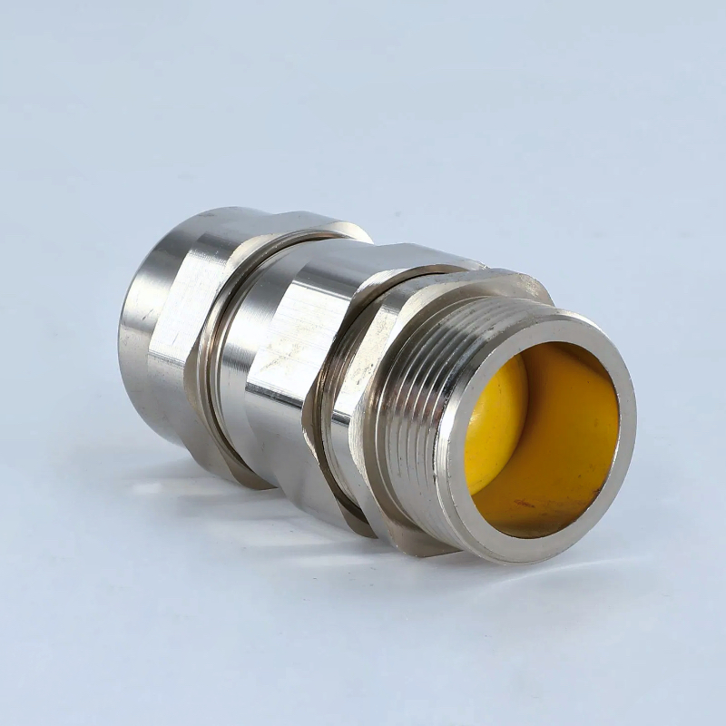
Compatible cable glands must provide enhanced sealing (IP68), corrosion resistance, and structural integrity while maintaining electrical performance during deluge system activation and long-term water exposure.
Selection requires understanding both normal operational requirements and emergency conditions that occur during deluge activation.
Enhanced Sealing Requirements
IP Rating Standards: IP68 represents the minimum acceptable rating, but the specific test conditions matter significantly. Look for glands tested to IP68 with continuous submersion rather than just temporary immersion ratings.
Seal Material Selection: Standard NBR seals may degrade under continuous water exposure. EPDM or silicone seals provide superior water resistance and temperature stability for deluge-protected installations.
Multiple Seal Barriers: Premium glands incorporate multiple sealing stages to provide redundancy during extended water exposure. This typically includes cable entry seals, thread seals, and internal barrier seals.
Material Compatibility
Body Materials: Stainless steel 316L provides optimal corrosion resistance for marine deluge environments. Brass may be acceptable for fresh water systems but requires protective coatings for seawater exposure.
Hardware Specifications: All bolts, nuts, and washers must use marine-grade stainless steel or super-duplex materials. Standard carbon steel hardware will fail rapidly in deluge-protected environments.
Electrical Continuity: Explosion-proof installations require continuous electrical bonding through the gland assembly. Ensure all components maintain conductivity despite potential corrosion or coating damage.
Performance Verification
Hassan, our petrochemical facility contact in Saudi Arabia, learned the importance of proper testing when his initial cable gland selection failed after just six months of deluge system testing. The seals couldn’t handle the thermal cycling between hot desert conditions and cool deluge water. We provided glands with EPDM seals rated for -40°C to +150°C, and they’ve performed flawlessly through quarterly deluge tests for over three years.
Factory Testing: Reputable manufacturers provide comprehensive test certificates including IP rating verification, corrosion resistance testing, and thermal cycling performance data.
Field Verification: Installation should include pressure testing and seal integrity verification before system commissioning. Regular inspection schedules must account for the aggressive deluge environment.
Conclusion
Deluge Protection (DTS01) represents a critical safety system for offshore cable gland installations, providing essential fire suppression capability in hazardous environments where traditional protection methods prove inadequate. Success requires careful integration of detection systems, water distribution networks, and specially designed cable glands capable of maintaining integrity during emergency activation.
The key to effective deluge protection lies in understanding the unique challenges of offshore environments and selecting components specifically designed for these demanding conditions. At Bepto, our marine-rated cable glands incorporate enhanced sealing systems, corrosion-resistant materials, and proven designs that maintain reliability throughout deluge system operation. With proper specification and installation, these systems provide the robust protection essential for offshore safety and regulatory compliance.
FAQs About Deluge Protection for Cable Glands
Q: What IP rating do cable glands need for deluge protection systems?
A: Cable glands require IP68 rating minimum for deluge applications, specifically tested for continuous submersion rather than temporary immersion. Enhanced sealing with EPDM or silicone gaskets provides optimal long-term performance.
Q: How often should deluge-protected cable glands be inspected?
A: Inspect quarterly during routine deluge system testing, with annual detailed inspections including seal integrity verification. Replace seals every 3-5 years or immediately if degradation is observed during testing.
Q: Can standard explosion-proof cable glands work with deluge systems?
A: Standard Ex-rated glands may not provide adequate water resistance for deluge environments. Specify marine-grade explosion-proof glands with enhanced sealing and corrosion-resistant materials for reliable deluge compatibility.
Q: What materials work best for cable glands in deluge-protected areas?
A: Stainless steel 316L provides optimal corrosion resistance for seawater deluge systems. All hardware must be marine-grade stainless steel, and seals should be EPDM or silicone for temperature and water resistance.
Q: How does deluge activation affect cable gland electrical performance?
A: Properly specified glands maintain electrical integrity during deluge activation through enhanced sealing and drainage design. However, some temporary performance degradation may occur until water drainage is complete after system shutdown.
-
Explore the role of DNV as a leading classification society and its standards for the maritime and offshore energy industries. ↩
-
Learn about the standards developed by the API to enhance operational safety and environmental protection in the oil and gas industry. ↩
-
Discover the operating principles of linear heat detectors for fire detection in industrial and hazardous environments. ↩
-
Understand how combined ultraviolet and infrared sensors are used to reliably detect fires while rejecting false alarms. ↩
-
Review the scope of this International Electrotechnical Commission standard for mobile and fixed offshore units. ↩
