Poor MC4 connector crimping causes 40% of solar system failures within the first five years, leading to power losses exceeding $2,000 per residential installation. Loose connections create resistance hotspots that can reach temperatures over 150°C, causing connector melting, arc faults1, and potential fire hazards. Traditional twist-on connections and improper crimping techniques result in degraded performance, safety risks, and voided warranties that cost installers thousands in callbacks and repairs.
Proper MC4 connector crimping requires specialized tools, correct wire stripping lengths, and precise compression force to create gas-tight connections that withstand 25+ years of thermal cycling2. Quality crimping tools apply 1,500-2,000 pounds of force with hexagonal dies that create uniform compression around the conductor. Professional-grade MC4 connectors with tin-plated copper contacts and UV-resistant housings ensure reliable connections that maintain less than 2mΩ resistance throughout their operational life.
Just two months ago, I helped James Mitchell, a solar installer from Phoenix, Arizona, who was experiencing frequent system failures due to overheating MC4 connections. His team was using basic crimping tools that created inconsistent connections, leading to 15% power losses and customer complaints. After switching to our professional MC4 crimping tools and IP68-rated3 connectors, his installations achieved zero connection failures over 8 months – boosting both system performance and customer satisfaction! ☀️
Table of Contents
- What Makes MC4 Connectors Critical for Solar Array Performance?
- What Tools and Materials Do You Need for Professional MC4 Crimping?
- How Do You Execute Perfect MC4 Connector Crimping Step-by-Step?
- What Are the Most Common MC4 Crimping Mistakes and How to Avoid Them?
- How Do You Test and Verify MC4 Connection Quality?
- FAQs About MC4 Connector Crimping
What Makes MC4 Connectors Critical for Solar Array Performance?
Understanding the electrical and mechanical demands placed on MC4 connectors helps explain why proper crimping techniques are essential for long-term solar system reliability.
MC4 connectors must handle 30+ amperes of DC current while maintaining electrical contact through 40+ years of thermal cycling from -40°C to +85°C. Poor connections create resistance that converts electrical energy to heat, reducing system efficiency and potentially causing dangerous arc faults. Quality MC4 connectors with proper crimping maintain contact resistance below 2mΩ, ensuring maximum power transfer and preventing thermal damage that can destroy entire solar arrays.
Electrical Performance Requirements
Current Carrying Capacity: MC4 connectors must safely handle continuous currents up to 30A without overheating, requiring perfect metal-to-metal contact achieved only through proper crimping techniques.
Voltage Isolation: Solar arrays operate at DC voltages up to 1,500V, demanding connectors with robust insulation and weatherproof sealing to prevent dangerous ground faults and arc incidents.
Contact Resistance4: Properly crimped MC4 connections maintain resistance below 2mΩ throughout their service life, while poor connections can exceed 50mΩ, causing significant power losses and overheating.
Environmental Durability Factors
Temperature Cycling: Daily temperature swings cause expansion and contraction that can loosen improperly crimped connections, leading to increased resistance and eventual failure.
UV Exposure: Continuous ultraviolet radiation degrades connector housings and seals, making proper assembly with quality materials essential for 25+ year performance.
Moisture Protection: Rain, snow, and humidity can penetrate poorly assembled connectors, causing corrosion and electrical faults that compromise system safety and performance.
System-Level Impact
Power Loss Calculations: A 5mΩ connection resistance in a 20A circuit wastes 2 watts continuously, totaling 17.5 kWh annually per connection – multiplied across hundreds of connections in large arrays.
Safety Considerations: Overheating connections can ignite surrounding materials, while arc faults from loose connections pose serious fire risks that proper crimping prevents.
Warranty Implications: Most solar panel manufacturers void warranties for installations using improperly terminated connectors, making professional crimping essential for long-term coverage.
What Tools and Materials Do You Need for Professional MC4 Crimping?
Professional MC4 crimping requires specialized tools and quality materials designed specifically for solar applications and outdoor environmental exposure.
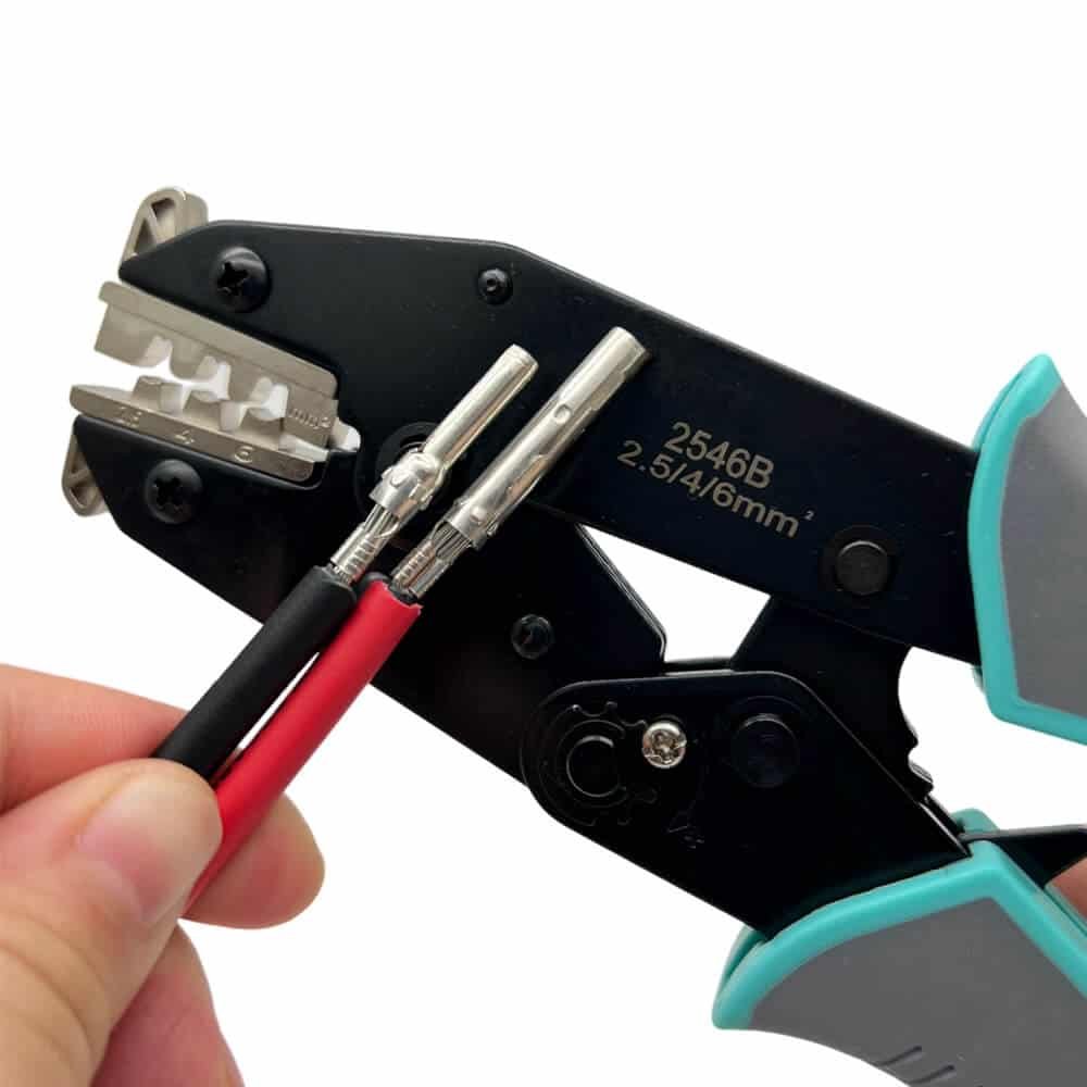
Professional MC4 crimping requires dedicated crimping tools with hexagonal dies, precision wire strippers, and quality connectors rated for solar applications. Proper tools apply 1,500-2,000 pounds of compression force with consistent die alignment, while quality MC4 connectors feature tin-plated copper contacts and UV-resistant housings. Using automotive or general electrical crimping tools creates unreliable connections that fail prematurely in solar environments.
Essential Crimping Tools
| Tool Type | Specifications | Purpose | Quality Indicators |
|---|---|---|---|
| MC4 Crimping Tool | 1,500-2,000 lbs force | Creates gas-tight connection | Hexagonal dies, ratcheting action |
| Wire Strippers | 10-14 AWG capacity | Precise insulation removal | Adjustable stops, clean cuts |
| Multimeter | 0.1mΩ resolution | Connection testing | True RMS, low resistance range |
| Torque Wrench | 2-10 Nm range | Assembly verification | Calibrated, click-type |
Professional Crimping Tool Features: Look for tools with interchangeable hexagonal dies, ratcheting mechanisms that prevent under-crimping, and ergonomic handles for extended use comfort.
Wire Preparation Tools: Quality wire strippers with adjustable depth stops ensure consistent insulation removal without nicking conductors that could create failure points.
Testing Equipment: Digital multimeters with milliohm resolution capability allow verification of connection quality before system energization.
MC4 Connector Quality Standards
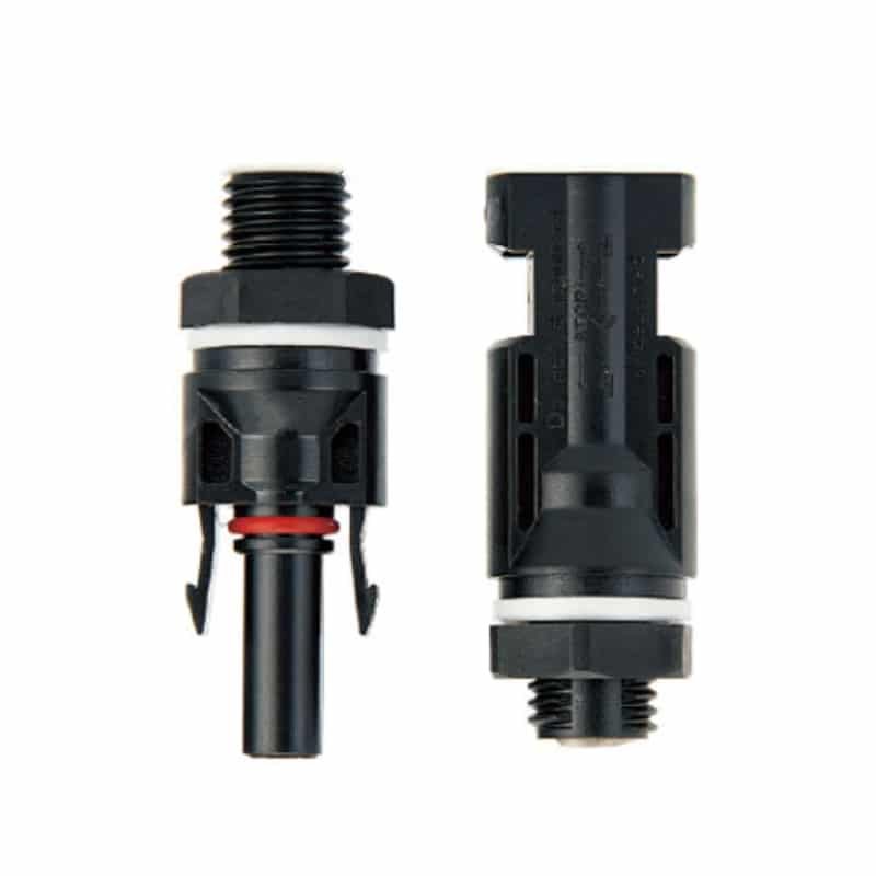
Contact Materials: Premium MC4 connectors use tin-plated copper contacts that resist corrosion while maintaining low electrical resistance over decades of service.
Housing Materials: UV-stabilized PPO (polyphenylene oxide) housings withstand continuous sun exposure without becoming brittle or cracking.
Sealing Systems: Double O-ring seals with silicone or EPDM materials provide IP68 protection against moisture ingress in all weather conditions.
Certification Requirements: Look for connectors with TUV, UL, or IEC certifications that verify performance under standardized solar application test conditions.
I recently worked with Sarah Chen, project manager for a 2MW solar farm in Seoul, South Korea, who was struggling with connection failures during commissioning. Their local supplier provided low-cost MC4 connectors that failed IP68 testing and showed high contact resistance. After switching to our TUV-certified MC4 connectors with proper crimping tools, they achieved 100% first-pass testing success – meeting their tight construction schedule while ensuring long-term reliability! 🔧
How Do You Execute Perfect MC4 Connector Crimping Step-by-Step?
Following a systematic crimping process ensures consistent, reliable connections that meet professional installation standards and manufacturer requirements.
Perfect MC4 crimping follows a precise sequence: strip wire to exact length, insert conductor fully into contact, position contact in crimping tool dies, apply full compression force, and verify crimp quality. Each step requires specific measurements and techniques – wire stripping length must match contact barrel depth, conductor insertion must be complete without strand protrusion, and crimping force must compress the contact uniformly around the entire conductor circumference.
Wire Preparation Process
Step 1 – Cable Selection: Use only solar-rated cables (PV wire) with tinned copper conductors and XLPE insulation rated for outdoor UV exposure and temperature extremes.
Step 2 – Length Measurement: Strip insulation to precisely 7mm length using adjustable wire strippers – too short reduces contact area, too long risks short circuits.
Step 3 – Conductor Inspection: Examine stripped conductor for nicks, broken strands, or contamination that could compromise connection integrity.
Step 4 – Strand Preparation: Twist stranded conductors slightly to prevent strand separation during insertion, but avoid over-twisting that increases conductor diameter.
Contact Crimping Technique
Step 5 – Contact Insertion: Insert stripped conductor fully into MC4 contact until insulation meets the contact barrel entrance – partial insertion creates high-resistance connections.
Step 6 – Tool Positioning: Place loaded contact in crimping tool with conductor perpendicular to die faces and contact centered in the crimping cavity.
Step 7 – Compression Application: Squeeze crimping tool handles fully until ratcheting mechanism releases – partial compression creates unreliable connections prone to failure.
Step 8 – Crimp Inspection: Examine completed crimp for uniform compression, proper barrel deformation, and absence of conductor protrusion or damage.
Assembly and Verification
Step 9 – Housing Assembly: Insert crimped contact into MC4 housing until it clicks into position, ensuring proper seating and electrical connection.
Step 10 – Seal Installation: Install O-ring seals in proper grooves without twisting or pinching that could compromise waterproof integrity.
Step 11 – Final Assembly: Thread cable through strain relief and tighten to manufacturer specifications using calibrated torque wrench.
Step 12 – Connection Testing: Measure contact resistance using precision multimeter – properly crimped connections should read less than 2mΩ resistance.
What Are the Most Common MC4 Crimping Mistakes and How to Avoid Them?
Understanding and avoiding common crimping errors prevents the connection failures that cause system downtime, safety hazards, and expensive repairs.
The most common MC4 crimping mistakes include insufficient wire stripping, incomplete conductor insertion, under-crimping with inadequate compression force, and using wrong tools designed for other applications. These errors create high-resistance connections that overheat, corrode, and fail prematurely. Proper training, quality tools, and systematic procedures prevent 95% of crimping-related failures in solar installations.
Wire Preparation Errors
Incorrect Strip Length: Stripping too little insulation prevents full conductor insertion, while excessive stripping risks short circuits and reduces insulation protection.
Conductor Damage: Using dull or improperly adjusted strippers can nick individual strands, reducing current-carrying capacity and creating stress concentration points.
Contamination Issues: Oil, dirt, or oxidation on conductor surfaces increases contact resistance and prevents proper metal-to-metal bonding during crimping.
Crimping Process Failures
Insufficient Compression: Under-crimping with inadequate force leaves gaps between conductor and contact, creating high resistance and potential for loosening over time.
Tool Misalignment: Improper positioning in crimping dies creates uneven compression that concentrates stress and reduces connection reliability.
Wrong Tool Usage: Using automotive or general electrical crimping tools lacks the force and die geometry needed for reliable MC4 connections.
Quality Control Oversights
Skip Testing: Failing to verify connection resistance allows defective crimps to remain in the system where they will eventually fail and cause problems.
Visual Inspection Only: Relying solely on visual appearance without electrical testing misses internal connection problems that aren’t externally visible.
Documentation Gaps: Not recording crimp quality data makes troubleshooting difficult when connection problems occur months or years later.
Prevention Strategies
| Error Type | Prevention Method | Verification Step | Consequence of Failure |
|---|---|---|---|
| Strip Length | Use adjustable strippers | Measure with ruler | Poor contact/shorts |
| Under-crimping | Ratcheting tools only | Resistance testing | Overheating/failure |
| Wrong Tools | MC4-specific equipment | Force verification | Inconsistent quality |
| No Testing | Mandatory resistance check | Document results | Hidden defects |
How Do You Test and Verify MC4 Connection Quality?
Comprehensive testing and verification procedures ensure MC4 connections meet performance standards and will provide reliable service throughout the solar system’s operational life.
MC4 connection testing requires contact resistance measurement, pull testing for mechanical strength, and insulation resistance verification. Properly crimped connections should measure less than 2mΩ resistance, withstand 50+ pounds pull force, and show greater than 1GΩ insulation resistance. Testing immediately after crimping and before system energization prevents field failures and ensures compliance with electrical codes and manufacturer warranties.
Electrical Testing Procedures
Contact Resistance Testing: Use a precision multimeter with milliohm capability to measure resistance across the crimped connection – readings above 2mΩ indicate poor crimping quality.
Insulation Resistance: Apply 500V DC between conductor and housing to verify insulation integrity – readings below 1GΩ suggest contamination or damage.
Voltage Drop Testing: Under load conditions, measure voltage drop across connections – excessive drops indicate high resistance that will cause overheating.
Mechanical Verification
Pull Testing: Apply gradually increasing force to verify mechanical connection strength – properly crimped connections should withstand 50+ pounds without separation.
Visual Inspection: Examine crimp barrel for uniform compression, proper depth, and absence of conductor protrusion or housing damage.
Torque Verification: Check strain relief and housing assembly torque using calibrated torque wrench to ensure proper mechanical integrity.
Documentation and Traceability
Test Records: Document all test results with connector location, technician identification, and date for future troubleshooting reference.
Quality Trends: Track crimp quality statistics to identify tool wear, training needs, or material quality issues before they cause field failures.
Certification Compliance: Maintain test documentation to demonstrate compliance with electrical codes, manufacturer requirements, and insurance standards.
Conclusion
Professional MC4 connector crimping is the foundation of reliable solar installations that deliver decades of trouble-free performance. Using proper tools, following systematic procedures, and verifying connection quality through comprehensive testing ensures your solar arrays achieve maximum efficiency while meeting safety standards. Remember that investing in quality crimping tools and training pays dividends through reduced callbacks, improved customer satisfaction, and long-term system reliability. At Bepto, we provide the professional-grade MC4 connectors and crimping tools that solar installers trust for mission-critical applications worldwide.
FAQs About MC4 Connector Crimping
Q: What happens if I use regular electrical crimping tools instead of MC4-specific tools?
A: Regular crimping tools lack the force and die geometry needed for reliable MC4 connections, typically applying only 500-800 pounds versus the 1,500-2,000 pounds required. This creates loose connections that overheat, corrode, and fail prematurely, often voiding equipment warranties.
Q: How can I tell if my MC4 crimp is good quality without special testing equipment?
A: A properly crimped MC4 connection shows uniform barrel compression with no conductor protrusion, requires significant force to separate during pull testing, and feels solid without movement between contact and housing. However, electrical testing with a multimeter is essential for verification.
Q: Can I reuse MC4 connectors if I need to make changes to my solar array?
A: MC4 connectors are designed for single-use applications and should not be reused after crimping. The compression deforms the contact permanently, and attempting to re-crimp creates unreliable connections that may fail unpredictably.
Q: What wire gauge should I use with standard MC4 connectors?
A: Standard MC4 connectors accommodate 10-14 AWG wire sizes, with 12 AWG being most common for residential installations. Always verify connector specifications match your wire gauge, as mismatched sizes create poor connections regardless of crimping quality.
Q: How often should I replace my MC4 crimping tools?
A: Professional MC4 crimping tools typically last 10,000-20,000 crimps before requiring replacement or refurbishment. Monitor crimp quality through regular testing and replace tools when they no longer achieve consistent low-resistance connections or show visible wear in the dies.
-
Understand the causes and dangers of DC arc faults in solar arrays and the standards for their prevention. ↩
-
Learn how daily temperature changes cause material expansion and contraction, leading to the failure of electrical connections over time. ↩
-
Review the official Ingress Protection (IP) rating system to understand what IP68 certification means for waterproofing and dust protection. ↩
-
Explore the electrical principles of contact resistance and its impact on power loss and heat generation in connections. ↩
