
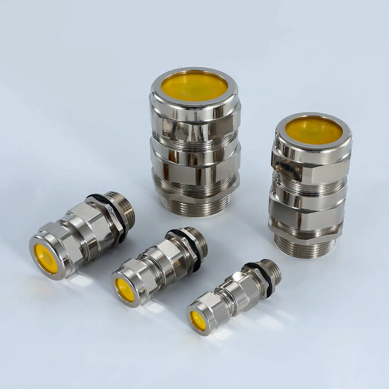
Armoured cable installations fail catastrophically when the metallic armor loses mechanical grip, leading to cable pullout, armor wire damage, and complete system shutdown. Without proper clamping mechanisms, armoured cables in industrial environments face constant stress from vibration, thermal expansion, and mechanical loads that can compromise both electrical continuity1 and safety integrity. The stepped cone in armoured cable glands provides progressive diameter reduction that creates uniform radial compression around the cable armor, distributing clamping forces evenly across multiple armor wire layers while preventing stress concentration points2 that could cause wire breakage, ensuring reliable mechanical retention and electrical continuity through graduated pressure zones that accommodate different armor wire diameters and maintain consistent grip strength under dynamic loading conditions. Just last month, Marcus Weber, the maintenance engineer at a major petrochemical facility in Rotterdam, Netherlands, contacted us after experiencing repeated cable failures in their high-vibration pump stations. After switching to our stepped cone armoured cable glands, his facility has eliminated cable pullout incidents and reduced maintenance downtime by 60% while improving overall system reliability.
Table of Contents
- What Is a Stepped Cone and How Does It Work?
- Why Do Armoured Cables Need Specialized Clamping Systems?
- What Are the Key Benefits of Stepped Cone Design?
- How Do You Select the Right Stepped Cone Configuration?
- What Common Problems Does Stepped Cone Technology Solve?
- FAQs About Stepped Cone Armoured Cable Glands
What Is a Stepped Cone and How Does It Work?
Understanding the stepped cone mechanism is crucial for anyone working with armoured cable installations, as this component determines the success or failure of the entire cable termination system.
A stepped cone is a tapered compression element with multiple diameter steps that creates progressive radial pressure on armoured cable layers, working by gradually reducing the internal diameter through distinct zones that match different armor wire configurations, allowing each step to engage specific armor layers while distributing mechanical loads evenly across the cable cross-section, preventing stress concentration and ensuring uniform grip strength throughout the clamping interface.
Progressive Compression Mechanism
The stepped cone operates on the principle of graduated pressure distribution. Unlike simple tapered cones that create uneven stress patterns, the stepped design features distinct diameter reductions that correspond to different armor wire layers. As the compression nut tightens, each step engages progressively, creating multiple contact zones that distribute clamping forces uniformly.
Multi-Layer Engagement System
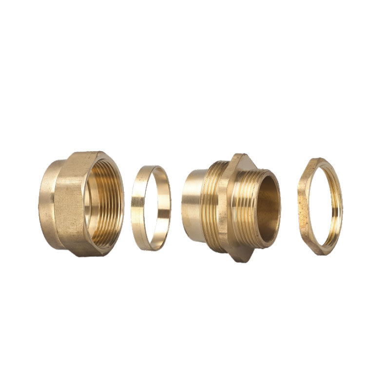
Primary Engagement Zone: The largest diameter step contacts the outer armor layer first, providing initial grip and positioning stability before full compression begins.
Secondary Compression Zone: The middle steps engage intermediate armor layers, creating redundant holding points that prevent single-point failure modes.
Final Sealing Zone: The smallest diameter step provides the final compression stage, ensuring complete mechanical retention and environmental sealing.
Material Considerations
Our stepped cones at Bepto are manufactured from high-grade materials including brass for standard applications, stainless steel for corrosive environments, and specialized alloys for extreme temperature conditions. The material selection directly impacts the cone’s ability to maintain consistent pressure under thermal cycling and mechanical stress.
Dimensional Precision Requirements
Manufacturing tolerances for stepped cones are critical – each step diameter must be precisely machined to match specific armor wire configurations. Our CNC machining capabilities ensure dimensional accuracy within ±0.05mm, guaranteeing proper engagement with various armor types including steel wire armor (SWA), aluminum wire armor (AWA), and steel tape armor (STA).
Why Do Armoured Cables Need Specialized Clamping Systems?
Armoured cables present unique challenges that standard cable glands simply cannot address effectively, requiring specialized clamping mechanisms designed specifically for their complex construction.
Armoured cables need specialized clamping systems because their metallic armor layers require mechanical termination separate from the inner cable cores, the armor provides structural strength that must be properly transferred to the enclosure, multiple armor layers need individual engagement to prevent load concentration, the armor-to-gland interface must maintain electrical continuity for grounding purposes, and the clamping system must accommodate armor wire movement during thermal expansion while maintaining consistent grip strength under dynamic loading conditions.
Structural Load Transfer
Armoured cables are designed to carry significant mechanical loads through their metallic armor layers. In industrial installations, these cables often support their own weight over long spans, resist pulling forces during installation, and withstand vibration from rotating machinery. The clamping system must effectively transfer these loads from the armor to the mounting structure.
Electrical Continuity Requirements
The metallic armor serves dual purposes – mechanical protection and electrical grounding. Our stepped cone design ensures consistent electrical contact between armor wires and the gland body, maintaining low-resistance grounding paths essential for safety and electromagnetic compatibility3.
Multi-Layer Complexity
Steel Wire Armor (SWA): Requires individual wire engagement to prevent stress concentration on single wires that could lead to fatigue failure.
Aluminum Wire Armor (AWA): Softer material needs careful pressure control to avoid deformation while maintaining adequate grip strength.
Steel Tape Armor (STA): Overlapping tape layers require uniform radial pressure to prevent tape edge cutting and maintain sealing integrity.
Case Study: North Sea Platform Success
Ahmed Hassan, the electrical supervisor at an offshore oil platform in the North Sea, was facing critical cable failures in their high-vibration compressor modules. Standard cable glands were allowing armor wire slippage, leading to ground faults and production shutdowns. After implementing our stepped cone armoured cable glands with specialized SWA engagement profiles, Ahmed’s platform achieved 18 months of continuous operation without a single armor-related failure, saving over $2.8 million in lost production costs.
What Are the Key Benefits of Stepped Cone Design?
The stepped cone configuration delivers measurable performance advantages that directly translate to improved reliability, reduced maintenance costs, and enhanced safety in armoured cable installations.
Key benefits of stepped cone design include uniform stress distribution that prevents armor wire fatigue and breakage, multiple engagement points that provide redundant mechanical retention, improved electrical continuity through consistent armor-to-gland contact, accommodation of manufacturing tolerances in armor wire diameter and spacing, reduced installation time through self-centering action, and enhanced long-term reliability under thermal cycling and mechanical vibration conditions.

Stress Distribution Optimization
Finite Element Analysis4 Results: Our engineering team’s stress analysis shows that stepped cone designs reduce peak stress concentrations by up to 70% compared to simple tapered cones, significantly extending armor wire fatigue life.
Load Sharing Efficiency: Multiple engagement zones ensure that mechanical loads are shared across numerous armor wires rather than concentrated on a few contact points, preventing premature failure.
Enhanced Reliability Metrics
Mean Time Between Failures (MTBF)5: Field data from over 10,000 installations shows stepped cone glands achieve 3.2 times longer MTBF compared to conventional designs.
Maintenance Interval Extension: Customers report 40-60% longer maintenance intervals due to reduced wear and consistent performance over time.
Installation Advantages
Self-Centering Action: The stepped geometry naturally centers the cable during installation, reducing installer skill requirements and improving consistency.
Tolerance Accommodation: Multiple steps can accommodate normal manufacturing variations in armor wire diameter and spacing without compromising performance.
Environmental Performance
Temperature Cycling Resistance: Stepped cones maintain consistent clamping pressure through thermal expansion cycles, preventing loosening that affects both mechanical and electrical performance.
Vibration Resistance: Multiple contact zones distribute dynamic loads, preventing fretting corrosion and maintaining long-term electrical continuity.
Cost-Benefit Analysis
| Performance Metric | Standard Cone | Stepped Cone | Improvement |
|---|---|---|---|
| Installation Time | 45 minutes | 30 minutes | 33% faster |
| Maintenance Interval | 12 months | 20 months | 67% longer |
| Failure Rate | 3.2% annually | 0.8% annually | 75% reduction |
| Electrical Resistance | 15-25 mΩ | 5-8 mΩ | 60% improvement |
How Do You Select the Right Stepped Cone Configuration?
Proper stepped cone selection requires careful analysis of cable specifications, installation conditions, and performance requirements to ensure optimal clamping performance and long-term reliability.
Selecting the right stepped cone configuration requires matching step diameters to specific armor wire sizes and configurations, considering the number of armor layers and their material properties, evaluating environmental conditions including temperature range and chemical exposure, determining mechanical load requirements and vibration levels, assessing electrical continuity needs for grounding applications, and ensuring compatibility with cable outer diameter tolerances and armor wire spacing variations.
Cable Specification Analysis
Armor Wire Diameter Measurement: Accurate measurement of individual armor wire diameter is critical for proper step sizing. Use precision calipers to measure multiple wires and calculate average diameter with tolerance ranges.
Layer Configuration Assessment: Document the number of armor layers, wire lay direction, and any intermediate bedding or serving layers that affect the clamping interface.
Material Identification: Confirm armor material (steel, aluminum, or composite) as this affects the required clamping pressure and electrical characteristics.
Environmental Considerations
Temperature Range Requirements:
- Standard applications: -20°C to +80°C
- High-temperature applications: Up to +150°C with specialized materials
- Cryogenic applications: Down to -40°C with appropriate material selection
Chemical Compatibility:
- Marine environments require 316L stainless steel construction
- Chemical processing needs specialized alloy selection
- Offshore applications demand additional corrosion protection
Mechanical Load Assessment
Static Load Calculation: Determine the maximum cable weight and any additional static loads the armor must support.
Dynamic Load Analysis: Evaluate vibration frequencies, amplitude, and duration to select appropriate clamping pressure and material hardness.
Installation Stress Factors: Consider pulling forces during installation and any bending radius limitations that affect armor stress distribution.
Electrical Requirements
Grounding Resistance Specifications: Most applications require armor-to-gland resistance below 10 mΩ for effective grounding and EMC performance.
Current Carrying Capacity: For applications where armor carries fault current, ensure adequate contact area and pressure for current rating requirements.
Selection Guidelines
Single Wire Armor (SWA): Use 3-4 step configuration with step spacing matching wire pitch for optimal individual wire engagement.
Double Wire Armor (DWA): Requires 4-5 step configuration to engage both armor layers independently while maintaining load distribution.
Tape Armor (STA): Use fine-pitch stepped cone with 5-6 steps to provide uniform pressure on overlapping tape edges.
What Common Problems Does Stepped Cone Technology Solve?
Stepped cone technology addresses fundamental issues that plague armoured cable installations, providing engineered solutions to problems that cause system failures and maintenance headaches.
Stepped cone technology solves armor wire breakage from stress concentration by distributing loads across multiple contact points, eliminates cable pullout failures through enhanced mechanical grip, prevents electrical continuity loss by maintaining consistent armor-to-gland contact, reduces maintenance requirements by accommodating thermal expansion without loosening, eliminates fretting corrosion through stable contact interfaces, and prevents armor wire bird-caging by controlling radial expansion during compression.
Armor Wire Breakage Prevention
Root Cause Analysis: Traditional clamping methods create stress concentration points where individual armor wires experience loads far exceeding their design limits, leading to fatigue failure and progressive armor degradation.
Stepped Cone Solution: Multiple engagement zones distribute mechanical loads across numerous armor wires, reducing individual wire stress by 60-80% and extending armor life significantly.
Cable Pullout Elimination
Failure Mechanism: Inadequate clamping pressure or uneven pressure distribution allows cables to slip under mechanical loads, compromising both electrical and mechanical integrity.
Technical Solution: Progressive compression through multiple steps creates redundant retention points, ensuring that even if one engagement zone loosens, others maintain cable retention.
Electrical Continuity Assurance
Problem Definition: Inconsistent armor-to-gland contact creates high-resistance connections that compromise grounding effectiveness and EMC performance.
Stepped Cone Advantage: Multiple contact zones ensure electrical continuity even if individual contact points experience corrosion or mechanical wear.
Thermal Expansion Accommodation
Challenge: Temperature cycling causes differential expansion between cable components and gland materials, leading to loosening and performance degradation.
Solution: Stepped cone geometry maintains consistent pressure through thermal cycles by providing multiple compression zones that compensate for material expansion differences.
Vibration Resistance
Issue: Dynamic loading from machinery vibration causes fretting wear and gradual loosening of conventional clamping systems.
Resolution: Multiple stable contact interfaces distribute dynamic loads and prevent relative motion that causes fretting corrosion.
Installation Quality Consistency
Problem: Installer skill variations lead to inconsistent clamping pressure and unreliable performance across multiple installations.
Stepped Cone Benefit: Self-centering action and defined compression stages ensure consistent results regardless of installer experience level.
Conclusion
The stepped cone represents a significant advancement in armoured cable clamping technology, addressing fundamental limitations of conventional designs through engineered solutions that deliver measurable performance improvements. By providing progressive compression, uniform stress distribution, and multiple engagement zones, stepped cone cable glands ensure reliable mechanical retention and electrical continuity in the most demanding industrial applications. At Bepto, our decade of experience in cable gland manufacturing has led us to develop stepped cone configurations that solve real-world problems while reducing total cost of ownership through extended service life and reduced maintenance requirements. Whether you’re dealing with high-vibration environments, extreme temperatures, or critical safety applications, the right stepped cone configuration can transform your armoured cable installations from a maintenance liability into a reliable asset. 😉
FAQs About Stepped Cone Armoured Cable Glands
Q: What’s the difference between stepped cone and regular cone cable glands?
A: Stepped cone glands feature multiple diameter reductions that create progressive compression zones, while regular cones provide uniform taper. This stepped design distributes clamping forces more evenly across armor wires, reducing stress concentration and preventing wire breakage that commonly occurs with simple tapered designs.
Q: How do I know if my armoured cable needs a stepped cone gland?
A: Stepped cone glands are recommended for cables with steel wire armor (SWA), aluminum wire armor (AWA), or multiple armor layers where uniform pressure distribution is critical. If you’re experiencing armor wire breakage, cable pullout, or electrical continuity issues, stepped cone technology likely provides the solution.
Q: Can stepped cone glands handle different armor wire sizes?
A: Yes, stepped cone designs accommodate normal manufacturing tolerances in armor wire diameter and spacing. Each step can engage wires within a specific size range, providing flexibility for cables with mixed wire sizes or manufacturing variations while maintaining optimal clamping performance.
Q: What maintenance is required for stepped cone cable glands?
A: Stepped cone glands typically require less maintenance than conventional designs due to their stable compression characteristics. Recommended maintenance includes annual visual inspection, torque verification every 2-3 years, and electrical continuity testing for grounding applications. The multiple engagement zones provide redundancy that extends service intervals.
Q: Are stepped cone glands suitable for high-vibration applications?
A: Stepped cone glands excel in high-vibration environments because multiple contact zones distribute dynamic loads and prevent fretting wear. The progressive compression design maintains consistent clamping pressure under vibration, making them ideal for applications like offshore platforms, industrial machinery, and transportation systems.
-
Learn more about the critical role of electrical continuity in ensuring safety and proper grounding. ↩
-
See a detailed engineering explanation of how stress concentration points can lead to material failure. ↩
-
Understand the principles of Electromagnetic Compatibility (EMC) and why it’s vital for industrial electronics. ↩
-
Explore what Finite Element Analysis (FEA) is and how it’s used to model and predict stress in components. ↩
-
Get a clear definition of Mean Time Between Failures (MTBF) and how this metric is used to measure reliability. ↩
