
High-density electrical installations face critical space constraints where traditional single-cable glands create overcrowding, excessive panel drilling, and compromised sealing that leads to moisture ingress, reduced IP ratings1, and costly installation delays in control panels, junction boxes, and equipment enclosures. Engineers struggle with balancing cable density requirements against maintaining proper environmental protection and installation efficiency in modern automation systems. Multi-hole cable glands for high-density cabling provide engineered solutions that accommodate multiple cables through single entry points while maintaining IP ratings, reducing panel modifications, and streamlining installation processes – these specialized glands feature individual cable sealing chambers, modular insert systems, and space-efficient designs that can handle 2-20+ cables per gland depending on configuration, delivering up to 70% space savings compared to individual glands while preserving environmental protection and simplifying cable management in dense electrical installations. Throughout my decade of experience supplying cable management solutions, I’ve witnessed how proper multi-hole gland selection transforms chaotic high-density installations into organized, maintainable systems that meet both space constraints and performance requirements while reducing installation time and long-term maintenance costs.
Table of Contents
- What Are Multi-Hole Cable Glands and How Do They Work?
- What Are the Key Benefits of Multi-Hole Cable Glands in High-Density Applications?
- How Do You Select the Right Multi-Hole Cable Gland Configuration?
- What Are the Installation Best Practices for Multi-Hole Cable Glands?
- What Common Mistakes Should Engineers Avoid?
- FAQs About Multi-Hole Cable Glands
What Are Multi-Hole Cable Glands and How Do They Work?
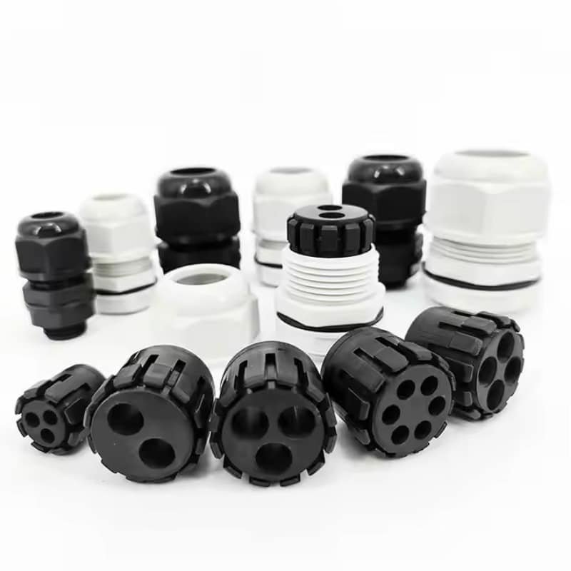
Multi-hole cable glands represent advanced cable entry solutions designed specifically for high-density installations where space efficiency and organized cable management are critical. Multi-hole cable glands are specialized cable entry devices that accommodate multiple cables through a single panel opening using individual sealing chambers, modular insert systems, or partitioned designs – they work by providing separate sealed pathways for each cable while maintaining overall environmental protection through compression sealing, gasket systems, and IP-rated construction that prevents moisture, dust, and contaminant ingress while allowing organized cable routing and simplified installation in space-constrained applications.
Design Architecture and Components
Modular Insert Systems utilize interchangeable rubber or elastomeric inserts with pre-formed holes sized for specific cable diameters, allowing customization of cable configurations while maintaining individual sealing for each cable entry point.
Individual Sealing Chambers provide dedicated compression zones for each cable, ensuring that environmental protection is maintained even if one cable is removed or replaced, preventing compromise of the entire gland assembly.
Progressive Compression Design features multiple compression stages that first seal individual cables, then create overall environmental sealing, ensuring both cable-specific and system-level protection against environmental ingress.
Operating Principles
Distributed Sealing Technology creates multiple independent seal points that prevent environmental ingress while accommodating different cable sizes and types within the same gland assembly, maintaining IP ratings across all entry points.
Space Optimization Geometry maximizes cable density through efficient internal routing and compact external dimensions, reducing panel space requirements by 50-70% compared to equivalent individual gland installations.
Flexible Configuration Options allow field customization of cable arrangements, with removable inserts and adjustable chambers accommodating changing cable requirements without complete gland replacement.
Material Construction Standards
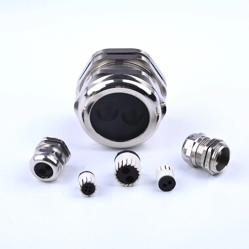
Housing Materials typically utilize brass, stainless steel, or engineered nylon depending on environmental requirements, with corrosion resistance and mechanical strength optimized for specific application conditions.
Sealing Components employ specialized elastomers and gasket materials designed for long-term compression set resistance2, chemical compatibility, and temperature stability in industrial environments.
Insert Materials use food-grade silicone, EPDM3, or NBR compounds selected for cable compatibility, environmental resistance, and compression characteristics that maintain sealing integrity over equipment lifetime.
James Mitchell, senior electrical engineer at Siemens’ automation facility in Munich, Germany, faced challenges installing control systems in compact machinery where traditional cable glands created excessive panel congestion and installation complexity. The project required routing 12 different sensor and control cables through a limited panel space while maintaining IP65 protection. We supplied our modular multi-hole cable glands with customizable inserts that accommodated the mixed cable sizes from 4mm to 12mm diameter. The solution reduced panel drilling from 12 holes to 3 holes while maintaining individual cable sealing and environmental protection, streamlining installation time by 60% and creating a much cleaner, more maintainable control panel layout.
What Are the Key Benefits of Multi-Hole Cable Glands in High-Density Applications?
Multi-hole cable glands deliver significant advantages in space-constrained installations where traditional solutions become impractical or inefficient. Key benefits of multi-hole cable glands in high-density applications include dramatic space savings of 50-70% compared to individual glands, reduced panel modification requirements that minimize drilling and machining costs, simplified cable management that improves organization and maintenance access, maintained environmental protection with individual cable sealing, faster installation times through consolidated entry points, and improved system reliability through reduced connection points – these advantages combine to deliver lower total installation costs, enhanced system performance, and simplified long-term maintenance in demanding high-density electrical applications.
Space Efficiency Advantages
Panel Real Estate Optimization allows engineers to fit more functionality into smaller enclosures, with multi-hole glands reducing required panel area by up to 70% compared to individual cable gland installations.
Reduced Drilling Requirements minimize panel modifications and associated costs, with single large openings replacing multiple smaller holes that require precise spacing and alignment for proper installation.
Improved Cable Routing creates organized pathways that prevent cable congestion and interference, allowing better airflow and heat dissipation within enclosures while maintaining accessibility for maintenance.
Installation and Cost Benefits
| Benefit Category | Traditional Glands | Multi-Hole Glands | Improvement |
|---|---|---|---|
| Panel Holes Required | 1 per cable | 1 per 4-20 cables | 75-95% reduction |
| Installation Time | 5-10 min/cable | 2-3 min/cable | 40-70% faster |
| Material Costs | High per connection | Lower per cable | 30-50% savings |
| Maintenance Access | Limited | Excellent | Significantly improved |
Environmental Protection Maintenance
Individual Cable Sealing ensures that environmental protection is maintained even when individual cables are removed or replaced, preventing system-wide seal compromise that can occur with shared sealing systems.
IP Rating Preservation maintains specified environmental protection levels across all cable entry points, with independent sealing chambers preventing cross-contamination between cable pathways.
Long-Term Reliability provides consistent environmental protection over equipment lifetime, with modular designs allowing seal replacement and maintenance without complete gland replacement.
System Performance Enhancements
Reduced Connection Points minimize potential failure modes and improve overall system reliability, with fewer individual components reducing maintenance requirements and failure probability.
Improved Cable Management enhances system organization and troubleshooting efficiency, with clearly defined cable pathways and groupings that simplify identification and maintenance procedures.
Enhanced Flexibility accommodates future modifications and expansions, with modular designs allowing cable configuration changes without major panel modifications or system downtime.
Economic Impact Analysis
Initial Cost Savings typically range from 20-40% compared to equivalent individual gland installations, including material costs, installation labor, and panel modification expenses.
Long-Term Maintenance Benefits reduce ongoing costs through improved accessibility, simplified troubleshooting, and reduced component count that minimizes replacement part inventory requirements.
Project Schedule Advantages accelerate installation timelines through consolidated cable entry points and reduced panel preparation requirements, particularly valuable in time-sensitive industrial projects.
How Do You Select the Right Multi-Hole Cable Gland Configuration?
Proper selection requires systematic analysis of cable requirements, environmental conditions, and installation constraints to optimize performance and cost-effectiveness. Select the right multi-hole cable gland configuration by analyzing cable specifications including diameters, types, and quantities, evaluating environmental requirements such as IP ratings, temperature ranges, and chemical exposure, determining space constraints and panel thickness limitations, and matching these requirements to appropriate gland designs – consider modular insert systems for mixed cable sizes, fixed-hole configurations for standardized cables, and specialized materials for harsh environments, ensuring selected configurations provide adequate safety factors while maintaining cost-effectiveness and installation simplicity.
Cable Specification Analysis
Cable Diameter Assessment requires accurate measurement of all cables including outer jackets, with consideration for manufacturing tolerances and potential cable variations that affect insert selection and sealing performance.
Cable Type Compatibility evaluation ensures selected gland materials and sealing compounds are compatible with cable jacket materials, preventing chemical degradation or sealing failures over equipment lifetime.
Quantity and Arrangement Planning determines optimal gland configuration based on total cable count, grouping requirements, and future expansion needs that may affect initial design decisions.
Environmental Requirements Evaluation
IP Rating Specifications must match application requirements, with consideration for both static and dynamic environmental conditions that may affect sealing performance and long-term reliability.
Temperature Range Analysis ensures selected materials maintain performance across expected operating conditions, including thermal cycling effects on sealing compounds and mechanical components.
Chemical Compatibility Assessment evaluates exposure to cleaning agents, process chemicals, and environmental contaminants that could affect gland materials and sealing integrity.
Configuration Selection Criteria
Modular vs. Fixed Designs depend on cable standardization levels, with modular systems preferred for mixed cable sizes and fixed configurations optimal for standardized cable installations.
Insert Material Selection based on cable compatibility, environmental conditions, and performance requirements, with different elastomer compounds optimized for specific application conditions.
Housing Material Choice considering corrosion resistance, mechanical strength, and cost requirements, with brass for general applications, stainless steel for corrosive environments, and nylon for cost-sensitive installations.
Sizing and Capacity Planning
Cable Density Optimization balances maximum cable capacity against sealing performance and installation convenience, avoiding over-packing that compromises environmental protection or maintenance access.
Future Expansion Considerations may justify larger gland sizes or additional spare positions to accommodate system modifications without major panel changes or additional gland installations.
Safety Factor Application ensures selected configurations provide adequate margin for cable variations, installation tolerances, and long-term performance requirements in demanding industrial environments.
Application-Specific Considerations
Control Panel Applications typically require organized cable grouping with clear identification and easy maintenance access, favoring modular designs with color-coded or labeled inserts.
Outdoor Installations demand enhanced environmental protection and UV resistance, requiring specialized materials and additional sealing measures for long-term reliability.
Hazardous Area Applications need certified explosion-proof or intrinsically safe designs with appropriate approvals for specific hazardous classifications and installation requirements.
Hassan Al-Rashid, operations manager at Saudi Aramco’s processing facility in Dhahran, Saudi Arabia, needed to upgrade aging control systems in their gas processing units where space limitations and harsh environmental conditions created significant challenges. The project involved routing 16 different instrumentation cables through limited panel space while maintaining ATEX certification4 and IP66 protection in a corrosive petrochemical environment. We provided our stainless steel multi-hole cable glands with specialized FFKM seals designed for hydrocarbon resistance and extreme temperature variations. The solution consolidated cable entries from 16 individual glands to 4 multi-hole units, maintaining all safety certifications while improving maintenance access and reducing long-term seal replacement costs in this demanding application.
What Are the Installation Best Practices for Multi-Hole Cable Glands?
Proper installation techniques ensure optimal performance and longevity while preventing common issues that compromise environmental protection or system reliability. Installation best practices for multi-hole cable glands include proper panel preparation with accurate hole sizing and edge finishing, systematic cable preparation with correct stripping lengths and identification, sequential assembly following manufacturer procedures to ensure proper sealing, appropriate torque application using calibrated tools to prevent over-compression or under-sealing, and comprehensive testing to verify environmental protection and cable security – following these practices prevents installation errors, ensures long-term reliability, and maintains warranty coverage while optimizing system performance and maintenance accessibility.
Panel Preparation Requirements
Hole Sizing Accuracy requires precise drilling or cutting to manufacturer specifications, with proper tolerances that ensure gland fit without excessive gaps or interference that could compromise sealing or installation.
Edge Finishing Standards demand smooth, burr-free openings that prevent seal damage during installation, with appropriate chamfering or deburring to protect elastomeric components during assembly.
Panel Thickness Verification ensures selected glands are compatible with actual panel dimensions, accounting for coating thickness, gasket compression, and thread engagement requirements for proper installation.
Cable Preparation Procedures
Length Planning requires careful measurement to ensure adequate cable length for routing and termination while avoiding excess that creates congestion or stress on connections.
Identification Systems should be implemented before installation to simplify troubleshooting and maintenance, with clear labeling that remains legible throughout equipment lifetime.
Protection During Installation prevents cable damage from sharp edges, contamination, or mechanical stress that could compromise performance or create safety hazards.
Assembly Sequence Optimization
Component Inspection verifies all parts are present and undamaged before beginning installation, preventing delays and ensuring proper assembly with all required sealing components.
Insert Selection and Installation requires matching cable diameters to appropriate insert holes, ensuring proper fit without excessive compression that could damage cables or insufficient sealing that compromises environmental protection.
Progressive Tightening follows manufacturer torque specifications in proper sequence to ensure even compression and optimal sealing performance across all cable entry points.
Quality Verification Methods
Seal Integrity Testing may include pressure testing, visual inspection, or leak detection methods appropriate for the application’s environmental protection requirements and criticality.
Cable Security Verification ensures adequate strain relief and proper cable retention without over-compression that could damage conductors or insulation systems.
Documentation Requirements should record installation parameters, torque values, and test results for future maintenance reference and warranty compliance.
Common Installation Challenges
Mixed Cable Sizes require careful insert selection and may need custom configurations to optimize sealing performance while accommodating all required cables within available space.
Access Limitations in confined spaces may require modified installation sequences or specialized tools to achieve proper assembly and torque application.
Environmental Conditions during installation can affect sealing compound performance and may require temperature conditioning or modified procedures for optimal results.
What Common Mistakes Should Engineers Avoid?
Understanding typical installation and specification errors helps prevent costly mistakes and ensures reliable system performance. Common mistakes engineers should avoid with multi-hole cable glands include over-packing cables that compromises sealing integrity, selecting inappropriate insert materials for cable types, inadequate panel preparation that creates sealing problems, incorrect torque application that damages components or creates leaks, mixing incompatible cable types in single glands, ignoring environmental compatibility requirements, and failing to plan for future maintenance access – these errors lead to premature failures, environmental ingress, safety hazards, and costly repairs that proper planning and installation practices can prevent.
Over-Packing and Capacity Errors
Excessive Cable Density compromises individual cable sealing and makes maintenance difficult, with over-packed glands unable to achieve proper compression on all cables simultaneously.
Inadequate Safety Margins fail to account for cable variations, thermal expansion, and long-term seal compression set that can reduce sealing effectiveness over time.
Ignoring Future Requirements creates situations where additional cables cannot be accommodated without major modifications or additional gland installations.
Material Compatibility Issues
Incompatible Seal Materials with cable jackets can cause chemical degradation, seal failure, and environmental ingress that may not be immediately apparent but creates long-term reliability problems.
Inappropriate Housing Materials for environmental conditions lead to corrosion, mechanical failure, and compromised environmental protection in harsh industrial applications.
Mixed Cable Types with different expansion characteristics or chemical compatibility requirements can create uneven sealing and potential failure modes.
Installation Technique Errors
Improper Torque Application either damages components through over-tightening or creates inadequate sealing through under-tightening, both compromising long-term performance and reliability.
Poor Panel Preparation with rough edges, incorrect hole sizes, or contaminated surfaces prevents proper sealing and may damage gland components during installation.
Inadequate Cable Preparation including incorrect stripping lengths, damaged jackets, or contaminated surfaces affects sealing performance and may create electrical or mechanical problems.
Design and Planning Mistakes
Insufficient Environmental Analysis leads to specification of inadequate protection levels or inappropriate materials for actual operating conditions and exposure requirements.
Poor Accessibility Planning creates maintenance difficulties and may require system shutdown or extensive disassembly for routine cable changes or troubleshooting.
Inadequate Documentation makes future maintenance and troubleshooting difficult, particularly in complex installations with multiple cable types and routing requirements.
Long-Term Reliability Oversights
Ignoring Thermal Cycling Effects on sealing compounds and mechanical components can lead to premature failures in applications with significant temperature variations.
Inadequate Vibration Considerations may cause mechanical loosening or fatigue failures in high-vibration environments without proper design margins and installation techniques.
Poor Maintenance Planning creates situations where routine maintenance becomes difficult or impossible without major system modifications or extended downtime.
Conclusion
Multi-hole cable glands provide essential solutions for high-density cabling applications where space efficiency, environmental protection, and installation simplicity are critical requirements. Proper selection based on cable specifications, environmental conditions, and installation constraints ensures optimal performance while avoiding common pitfalls that compromise reliability. Following best practices for installation and maintenance maximizes the benefits of these advanced cable management solutions while ensuring long-term system performance. At Bepto, we offer comprehensive multi-hole cable gland solutions with the technical expertise and quality components needed for successful high-density installations across diverse industrial applications! 😉
FAQs About Multi-Hole Cable Glands
Q: How many cables can fit in a multi-hole cable gland?
A: Multi-hole cable glands typically accommodate 2-20+ cables depending on gland size and cable diameters. Standard configurations handle 4-8 cables, while larger units can manage 12-20+ cables with proper insert selection and adequate panel space for installation.
Q: Do multi-hole cable glands maintain the same IP rating as single cable glands?
A: Yes, properly installed multi-hole cable glands maintain equivalent IP ratings to single cable glands through individual sealing chambers and proper compression systems. Each cable entry point provides independent environmental protection that prevents cross-contamination between cable pathways.
Q: Can I mix different cable sizes in one multi-hole cable gland?
A: Yes, modular multi-hole cable glands accommodate mixed cable sizes through interchangeable inserts with different hole configurations. This flexibility allows optimization of panel space while maintaining proper sealing for each individual cable diameter.
Q: What happens if I need to remove one cable from a multi-hole gland?
A: Individual cable removal is possible with modular designs by replacing the specific insert or using blank plugs to maintain environmental sealing. This prevents compromise of remaining cable seals and maintains overall gland integrity.
Q: Are multi-hole cable glands more expensive than individual glands?
A: Multi-hole cable glands typically cost 20-40% less than equivalent individual gland installations when considering total system costs including materials, installation labor, and panel modifications. The space savings and installation efficiency provide significant economic advantages in high-density applications.
-
Learn what IP (Ingress Protection) ratings mean and how they are defined. ↩
-
Get a technical definition of compression set and why it’s a critical property for seals. ↩
-
Explore the material properties, chemical resistance, and common applications of EPDM rubber. ↩
-
Understand the ATEX directive for equipment used in potentially explosive atmospheres. ↩
