Incorrect cable gland entry hole sizing causes installation failures, compromised IP ratings, cable damage, and safety hazards when oversized holes allow water ingress and undersized holes create cable stress, while improper hole preparation leads to costly rework, project delays, and equipment failures that could have been prevented with proper sizing calculations and installation procedures.
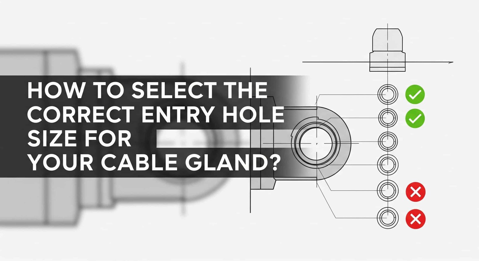
Selecting the correct entry hole size for cable glands requires measuring cable outer diameter, adding appropriate clearance tolerances, considering cable movement and thermal expansion, and following manufacturer specifications to ensure proper sealing, strain relief, and IP rating performance while preventing cable damage and maintaining long-term reliability in electrical installations. Proper hole sizing is critical for successful cable gland performance.
Having worked with electrical contractors across major projects in Germany’s automotive plants, offshore platforms in the North Sea, and data centers throughout Silicon Valley, I’ve seen how proper entry hole sizing can make or break an installation. Let me share proven methods for getting cable gland hole sizing right every time.
Table of Contents
- What Factors Determine Cable Gland Entry Hole Size Requirements?
- How Do You Measure and Calculate the Correct Hole Size?
- What Are the Standard Hole Sizes for Different Cable Gland Types?
- How Do You Properly Cut and Prepare Entry Holes?
- What Common Mistakes Should You Avoid When Sizing Entry Holes?
- FAQs About Cable Gland Entry Hole Sizing
What Factors Determine Cable Gland Entry Hole Size Requirements?
Cable gland entry hole size requirements are determined by cable outer diameter, cable type and construction, environmental sealing requirements, thermal expansion considerations, installation tolerances, and manufacturer specifications that ensure proper fit, sealing performance, strain relief, and long-term reliability while accommodating cable movement and maintaining IP ratings in various environmental conditions.
Understanding these factors ensures optimal cable gland performance and prevents common installation problems.
Cable Diameter Considerations
Outer Diameter Measurement: The cable’s outer diameter is the primary factor determining entry hole size, requiring accurate measurement at the point where the cable enters the gland.
Cable Tolerance Variations: Manufacturing tolerances can cause cable diameter variations of ±5-10%, requiring hole sizing that accommodates these variations.
Jacket Material Effects: Different jacket materials have varying flexibility and compression characteristics that affect how cables fit through entry holes.
Multi-Core Cable Considerations: Multi-core cables may have oval or irregular cross-sections that require special sizing considerations.
Environmental and Performance Requirements
IP Rating Maintenance: Entry hole size directly affects the cable gland’s ability to maintain specified IP ratings for dust and water protection.
Sealing Performance: Proper hole sizing ensures optimal compression of sealing elements for long-term environmental protection.
Strain Relief Function: Correct sizing allows the cable gland to provide proper strain relief without over-compression that could damage the cable.
Temperature Performance: Thermal expansion and contraction of cables and enclosures must be considered in hole sizing calculations.
Installation and Mounting Factors
Panel Thickness: The thickness of the mounting panel affects how the cable gland seats and seals in the entry hole.
Hole Edge Quality: Clean, smooth hole edges are essential for proper gasket sealing and preventing cable jacket damage.
Mounting Hardware: Some cable glands require additional clearance for mounting nuts, washers, or locking rings.
Access Requirements: Installation and maintenance access requirements may influence hole size and positioning decisions.
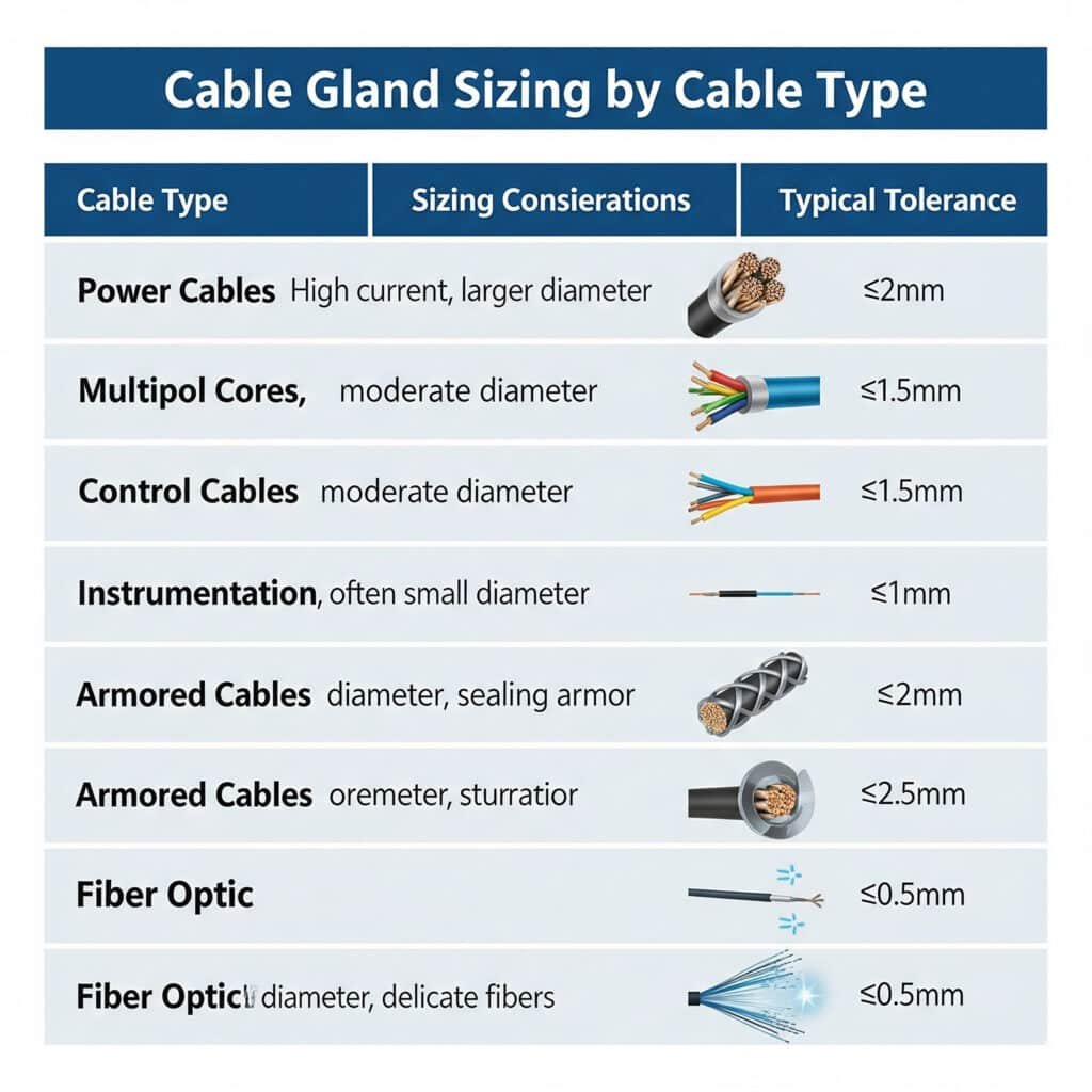
Cable Type Specific Requirements
| Cable Type | Sizing Considerations | Typical Tolerance |
|---|---|---|
| Power Cables | Rigid construction, minimal compression | +2-3mm |
| Control Cables | Flexible, moderate compression acceptable | +1-2mm |
| Instrumentation | Precise fit required, minimal movement | +0.5-1mm |
| Armored Cables | Large diameter, rigid construction | +3-5mm |
| Fiber Optic | Bend radius critical, gentle handling | +1-2mm |
Marcus, a project manager at a major automotive manufacturer in Stuttgart, faced repeated cable gland failures during production line installations. The maintenance team was drilling oversized holes “to make installation easier,” but this compromised IP65 ratings1 and allowed coolant contamination of electrical panels. We provided detailed hole sizing specifications and drilling templates that ensured proper fit while maintaining environmental protection, eliminating costly rework and production delays. 😊
How Do You Measure and Calculate the Correct Hole Size?
Measuring and calculating correct hole size requires using precision calipers to measure cable outer diameter at multiple points, adding manufacturer-specified clearances, considering cable deformation under compression, accounting for temperature expansion, and following established formulas that ensure proper sealing while preventing cable damage and maintaining environmental protection ratings.
Accurate measurement and calculation are essential for successful cable gland installations.
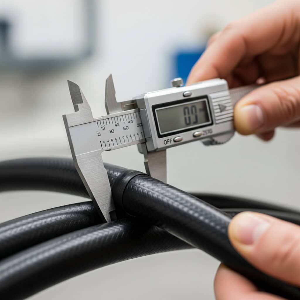
Cable Measurement Techniques
Multiple Point Measurement: Measure cable diameter at several points along the length to identify variations and determine maximum diameter.
Proper Measuring Tools: Use precision calipers or micrometers for accurate measurements, avoiding tape measures or rulers that lack sufficient precision.
Temperature Considerations: Measure cables at installation temperature conditions, as temperature affects cable diameter through thermal expansion.
Compression Testing: For flexible cables, test compression characteristics to understand how the cable will deform during installation.
Standard Calculation Methods
Basic Sizing Formula: Entry hole diameter = Cable outer diameter + Clearance allowance + Safety margin
Clearance Allowances: Typical clearances range from 0.5mm for precision applications to 3mm for large power cables.
Safety Margins: Additional 0.5-1mm safety margin accounts for measurement uncertainties and installation tolerances.
Manufacturer Specifications: Always verify calculations against manufacturer specifications for specific cable gland models.
Environmental Factor Adjustments
Temperature Expansion: Add 1-2% of cable diameter for installations with significant temperature variations.
Humidity Effects: Consider cable jacket swelling in high humidity environments, particularly for hygroscopic materials2.
Chemical Exposure: Account for potential cable jacket swelling when exposed to chemicals or solvents.
UV Degradation: Outdoor installations may experience cable jacket changes over time that affect fit.
Verification and Testing Methods
Test Fitting: Always perform test fitting with actual cables before final hole cutting to verify calculations.
Sealing Verification: Check that calculated hole size allows proper sealing element compression without over-compression.
Installation Force Testing: Verify that cables can be installed without excessive force that could damage cable or gland.
Performance Testing: Test IP rating performance after installation to confirm proper sealing.
Documentation and Quality Control
Measurement Records: Document all measurements and calculations for quality assurance and future reference.
Installation Drawings: Create detailed drawings showing hole sizes, locations, and installation requirements.
Inspection Checklists: Develop checklists to verify proper hole sizing before and after installation.
Revision Control: Maintain revision control for hole sizing specifications as projects evolve.
Ahmed, who manages electrical installations at a petrochemical facility in Kuwait, struggled with inconsistent cable gland performance due to varying hole sizes cut by different contractors. We developed standardized measurement procedures and calculation worksheets that ensured consistent hole sizing across all installation teams, improving first-time installation success rates from 75% to 98% and eliminating costly rework.
What Are the Standard Hole Sizes for Different Cable Gland Types?
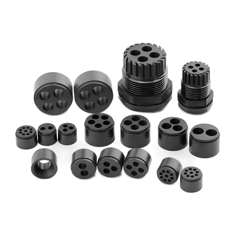
Standard hole sizes for cable glands vary by thread size, cable diameter range, and gland type, with metric cable glands requiring holes from 12mm for M12 glands to 75mm for M75 glands, NPT glands3 following different sizing standards, and specialized glands like armored cable glands requiring larger holes to accommodate their increased body diameter and sealing requirements.
Understanding standard sizing helps ensure proper selection and installation planning.
Metric Cable Gland Hole Sizes
M12 Cable Glands: 12mm hole diameter for cables 3-6.5mm, commonly used for instrumentation and control cables.
M16 Cable Glands: 16mm hole diameter for cables 4-10mm, popular for general-purpose electrical installations.
M20 Cable Glands: 20mm hole diameter for cables 6-12mm, widely used for power and control applications.
M25 Cable Glands: 25mm hole diameter for cables 9-16mm, suitable for medium power cables and multi-core applications.
M32 Cable Glands: 32mm hole diameter for cables 15-22mm, used for larger power cables and industrial applications.
NPT Cable Gland Hole Sizes
1/2″ NPT: 20.6mm hole diameter, equivalent to M20 metric sizing for North American applications.
3/4″ NPT: 26.7mm hole diameter, commonly used for industrial power applications.
1″ NPT: 33.4mm hole diameter, suitable for large cable installations and multiple cable entries.
1-1/4″ NPT: 42.2mm hole diameter, used for heavy-duty industrial applications.
1-1/2″ NPT: 48.3mm hole diameter, for very large cables and specialized applications.
Specialized Cable Gland Sizing
| Gland Type | Size Range | Hole Diameter | Special Considerations |
|---|---|---|---|
| Armored Cable | M20-M75 | +2-5mm over standard | Larger body diameter |
| EMC Shielded | M12-M63 | Standard sizing | Precise fit critical |
| Explosion-Proof | M16-M50 | +1-2mm over standard | Thread engagement critical |
| Marine Grade | M12-M75 | Standard sizing | Corrosion-resistant materials |
| High Temperature | M16-M40 | +1-2mm for expansion | Thermal expansion allowance |
Panel Thickness Considerations
Thin Panels (1-3mm): May require larger holes to accommodate gland body and ensure proper thread engagement.
Standard Panels (3-6mm): Optimal thickness for most cable glands, allowing proper seating and sealing.
Thick Panels (6-12mm): May require extended thread lengths or special mounting hardware.
Very Thick Panels (>12mm): Often require bulkhead-style glands or custom solutions.
Tolerance and Quality Requirements
Standard Tolerances: ±0.1mm for precision applications, ±0.2mm for general industrial use.
Surface Finish: Smooth hole edges prevent gasket damage and ensure proper sealing.
Perpendicularity: Holes must be perpendicular to panel surface within ±2 degrees for proper sealing.
Edge Quality: Deburred edges prevent cable jacket damage during installation.
How Do You Properly Cut and Prepare Entry Holes?
Properly cutting and preparing entry holes requires selecting appropriate cutting tools, marking hole centers accurately, using proper cutting speeds and feeds, deburring all edges, checking dimensional accuracy, and applying protective finishes to ensure clean, precise holes that provide optimal sealing surfaces and prevent cable damage during installation and service.
Quality hole preparation is essential for long-term cable gland performance and reliability.
Hole Cutting Methods and Tools
Step Drill Bits: Ideal for thin panels, providing clean holes with minimal burring and good size control.
Hole Saws: Excellent for thicker panels and larger holes, requiring proper speed and feed rates for clean cuts.
Plasma Cutting: Fast for thick panels but requires extensive finishing to achieve proper surface quality.
Water jet cutting4: Provides excellent precision and surface finish but may be cost-prohibitive for small quantities.
Punching: Fast and economical for thin panels but limited to smaller hole sizes and softer materials.
Cutting Process Best Practices
Proper Marking: Use center punches and precision measuring tools to mark hole centers accurately.
Cutting Speed Control: Use appropriate speeds to prevent overheating and ensure clean cuts without work hardening.
Coolant Application: Apply cutting fluid when necessary to prevent overheating and extend tool life.
Progressive Cutting: For large holes, use progressive cutting techniques to maintain accuracy and prevent material distortion.
Backup Support: Support thin panels during cutting to prevent distortion and ensure clean breakthrough.
Quality Control and Inspection
Dimensional Verification: Measure all holes with precision tools to verify diameter and roundness within specified tolerances.
Edge Quality Inspection: Check for burrs, tears, or other edge defects that could affect sealing or damage cables.
Surface Finish Assessment: Verify surface finish meets requirements for proper gasket sealing and corrosion resistance.
Perpendicularity Check: Verify holes are perpendicular to panel surface using appropriate measuring tools.
Finishing and Protection
Deburring: Remove all burrs and sharp edges using appropriate deburring tools or processes.
Edge Radiusing: Slightly radius hole edges to prevent cable jacket damage during installation.
Protective Coating: Apply appropriate protective coatings to prevent corrosion and maintain surface quality.
Final Cleaning: Clean holes thoroughly to remove cutting debris and contaminants before cable gland installation.
Common Cutting Problems and Solutions
Oversized Holes: Caused by tool wear, excessive feed rates, or improper tool selection – prevent through proper tool maintenance and cutting parameters.
Rough Edges: Result from dull tools, incorrect speeds, or inadequate support – address through proper tool selection and cutting techniques.
Out-of-Round Holes: Caused by machine deflection, worn tools, or improper setup – prevent through proper machine maintenance and setup procedures.
Work hardening5: Results from excessive heat generation – control through proper speeds, feeds, and coolant application.
What Common Mistakes Should You Avoid When Sizing Entry Holes?
Common mistakes in entry hole sizing include oversizing holes for “easier installation,” undersizing based on nominal cable dimensions, ignoring manufacturer specifications, failing to account for cable variations, using inappropriate measuring tools, neglecting thermal expansion, and cutting holes before final cable selection, all of which compromise sealing performance, IP ratings, and long-term reliability.
Avoiding these mistakes ensures successful cable gland installations and optimal performance.
Sizing Calculation Errors
Using Nominal Dimensions: Relying on cable catalog dimensions instead of measuring actual cables leads to poor fit and sealing problems.
Ignoring Tolerances: Failing to account for manufacturing tolerances in both cables and panels causes installation difficulties.
Inadequate Clearances: Insufficient clearance makes installation difficult and may damage cables or compromise sealing.
Excessive Clearances: Oversized holes compromise sealing performance and may violate IP rating requirements.
Measurement and Documentation Mistakes
Inaccurate Measuring Tools: Using inappropriate measuring tools leads to sizing errors and installation problems.
Single Point Measurement: Measuring cable diameter at only one point misses variations that affect hole sizing.
Temperature Neglect: Failing to consider temperature effects on cable dimensions causes fit problems in service.
Poor Documentation: Inadequate documentation leads to confusion and inconsistent hole sizing across installations.
Installation Planning Errors
Premature Hole Cutting: Cutting holes before final cable selection locks in sizing that may not accommodate actual cables.
Ignoring Panel Thickness: Failing to consider panel thickness effects on gland seating and thread engagement.
Access Limitations: Not considering installation access requirements when positioning and sizing holes.
Future Expansion: Failing to plan for potential cable changes or additions in the future.
Quality Control Oversights
Skipping Test Fits: Failing to test fit cables and glands before final installation can reveal sizing problems too late.
Inadequate Inspection: Not properly inspecting hole quality before installation leads to sealing and performance problems.
Missing Verification: Failing to verify IP rating performance after installation may not detect sizing-related problems.
Poor Record Keeping: Inadequate documentation makes troubleshooting and maintenance difficult.
Environmental Factor Neglect
Temperature Expansion: Ignoring thermal expansion effects can cause cables to bind or seals to fail.
Chemical Compatibility: Not considering chemical effects on cable dimensions can lead to fit problems over time.
Aging Effects: Failing to account for cable aging and dimensional changes affects long-term performance.
Installation Conditions: Not considering installation environment conditions can affect cable handling and fit.
Conclusion
Selecting the correct entry hole size for cable glands requires careful measurement, proper calculation methods, and attention to environmental factors. Following manufacturer specifications and industry best practices ensures optimal sealing performance, IP rating compliance, and long-term reliability.
Success depends on accurate measurement, proper calculation, quality hole preparation, and avoiding common sizing mistakes. At Bepto, we provide comprehensive technical support and detailed specifications to help you achieve perfect cable gland installations every time, backed by our extensive experience in cable connection solutions.
FAQs About Cable Gland Entry Hole Sizing
Q: What happens if my cable gland entry hole is too big?
A: Oversized holes compromise sealing performance and IP ratings by preventing proper gasket compression. This allows water and dust ingress, potentially causing electrical faults and equipment damage. The hole should match manufacturer specifications within ±0.2mm tolerance.
Q: How do I measure cable diameter accurately for hole sizing?
A: Use precision calipers to measure cable outer diameter at multiple points along the length, taking the maximum measurement. Measure at installation temperature and add manufacturer-specified clearances, typically 1-3mm depending on cable type and gland size.
Q: Can I use the same hole size for different cable gland brands?
A: Not necessarily – different manufacturers may have varying body diameters and sealing requirements even for the same thread size. Always verify hole size requirements with the specific manufacturer’s specifications and test fit before final installation.
Q: What’s the best tool for cutting cable gland entry holes?
A: Step drill bits work best for thin panels and smaller holes, while hole saws are ideal for thicker panels and larger diameters. Both provide clean cuts with minimal burring when used at proper speeds with appropriate cutting fluid.
Q: How much clearance should I add to the cable diameter for the entry hole?
A: Add 1-3mm clearance depending on cable type: 1mm for instrumentation cables, 2mm for control cables, and 3mm for power cables. Always verify against manufacturer specifications and account for temperature expansion in outdoor installations.
-
Understand what the IP65 rating signifies for protection against dust and low-pressure water jets according to international standards. ↩
-
Learn about hygroscopy, the property of materials to absorb moisture from the surrounding air, and how it can affect them. ↩
-
Explore the technical specifications of the NPT (National Pipe Taper) thread standard used widely in the United States. ↩
-
Discover the technology behind abrasive water jet cutting, a precision process that uses a high-pressure stream of water and abrasive particles. ↩
-
Review the metallurgical phenomenon of work hardening, where a metal becomes stronger and harder through plastic deformation. ↩
