
Vibration and shock are silent killers in industrial environments, causing cable failures, connection loosening, and costly equipment downtime that can devastate production schedules and safety systems. From mining operations to marine vessels, from railway systems to heavy manufacturing, mechanical stress on electrical connections leads to billions of dollars in losses annually. The right cable gland for vibration and shock mitigation requires specialized strain relief design, vibration-dampening materials like reinforced nylon or metal with flexible sealing systems, proper cable clamping mechanisms that distribute stress evenly, and compliance with shock/vibration standards such as IEC 600681 to ensure reliable electrical connections in dynamic mechanical environments. Just last week, I received a call from Robert, the maintenance manager at a steel processing plant in Pittsburgh, Pennsylvania, who was experiencing recurring cable failures on their overhead crane systems. After switching to our armored cable glands with enhanced strain relief and vibration-resistant sealing, his facility reduced cable-related downtime by 85% and eliminated the weekly cable replacements that were costing them thousands in lost production time.
Table of Contents
- What Causes Vibration and Shock Damage to Cable Connections?
- Which Cable Gland Features Provide the Best Vibration Protection?
- How Do Different Materials Handle Mechanical Stress?
- What Installation Techniques Maximize Vibration Resistance?
- How Does Bepto Design Cable Glands for High-Vibration Applications?
- FAQs About Vibration-Resistant Cable Glands
What Causes Vibration and Shock Damage to Cable Connections?
Understanding the root causes of vibration and shock damage is essential for selecting appropriate cable gland solutions and preventing costly failures in dynamic environments.
Vibration and shock damage to cable connections occurs through mechanical fatigue2 from repeated stress cycles, cable jacket abrasion against gland surfaces, loosening of threaded connections due to dynamic loading, conductor wire breakage from flexing stress, seal degradation from constant movement, and resonance amplification3 when equipment vibration frequencies match cable natural frequencies, leading to accelerated wear and eventual electrical failure.

Primary Vibration Sources
Rotating Machinery:
Motors, pumps, compressors, and turbines generate continuous vibration at specific frequencies that can create resonance conditions in cable systems, leading to accelerated fatigue and connection failures.
Impact Loading:
Heavy machinery operations, pile driving, stamping presses, and material handling equipment create shock loads that stress cable connections beyond their design limits.
Transportation Vibration:
Railway systems, marine vessels, mobile equipment, and automotive applications subject cables to multi-directional vibration with varying frequencies and amplitudes.
Environmental Forces:
Wind loading on outdoor installations, seismic activity, and thermal expansion/contraction cycles create additional mechanical stress on cable gland connections.
Failure Mechanisms
Mechanical Fatigue:
Repeated stress cycles cause microscopic crack initiation and propagation in cable gland materials, eventually leading to complete structural failure of the connection system.
Fretting Corrosion4:
Small amplitude vibration between metal surfaces creates wear particles and corrosion products that degrade electrical connections and sealing performance.
Cable Jacket Damage:
Abrasion between the cable outer jacket and gland interior surfaces creates entry points for moisture and contaminants, compromising system integrity.
Conductor Breakage:
Flexing stress concentrates at the cable entry point, causing individual conductor wires to break and creating intermittent or complete circuit failures.
Resonance Amplification
Natural Frequency Matching:
When equipment vibration frequencies match the natural frequency of cable systems, resonance amplification can increase stress levels by factors of 10-50 times normal operating conditions.
Harmonic Excitation:
Multiple vibration sources can create complex harmonic patterns that excite cable systems at unexpected frequencies, leading to unpredictable failure modes.
Standing Wave Formation:
Long cable runs can develop standing wave patterns that concentrate stress at specific points, typically near cable gland connections where flexibility changes occur.
Which Cable Gland Features Provide the Best Vibration Protection?
Effective vibration protection requires specific cable gland design features that address the unique challenges of dynamic mechanical environments.
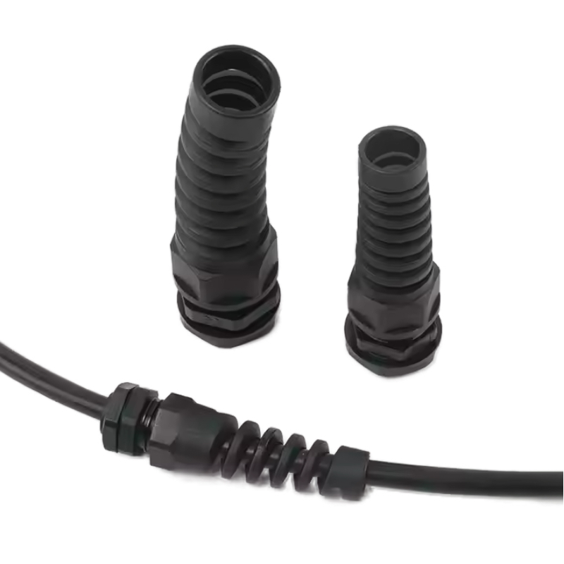
The best vibration protection features in cable glands include progressive strain relief systems that gradually transition cable flexibility, multi-point cable clamping to distribute stress over larger areas, vibration-dampening sealing materials like specialized elastomers, reinforced thread designs to prevent loosening, flexible cable armor support systems, and integrated shock absorption elements that isolate cables from direct mechanical transmission while maintaining electrical continuity and environmental sealing.
Advanced Strain Relief Systems
Progressive Flexibility Transition:
The most effective cable glands feature graduated strain relief that gradually transitions from the rigid gland body to the flexible cable, preventing stress concentration at a single point.
Multi-Stage Clamping:
Multiple clamping points distribute mechanical stress over a longer cable length, reducing peak stress levels and improving fatigue resistance.
Conical Strain Relief Design:
Tapered strain relief elements provide optimal stress distribution while accommodating different cable diameters and maintaining consistent clamping pressure.
Vibration-Dampening Materials
Specialized Elastomers:
Advanced rubber compounds with high damping coefficients absorb vibration energy and reduce transmission to cable conductors while maintaining sealing performance.
Composite Strain Relief Elements:
Fiber-reinforced polymer components provide controlled flexibility with enhanced fatigue resistance compared to standard materials.
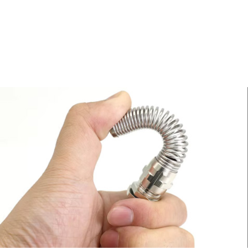
Metallic Damping Systems:
Engineered metal bellows or spring systems provide controlled flexibility while maintaining structural integrity in high-stress applications.
Enhanced Sealing Systems
Dynamic Seal Design:
Sealing systems specifically designed for movement accommodate cable flexing while maintaining IP ratings5 and preventing contamination ingress.
Multiple Sealing Barriers:
Redundant sealing elements provide backup protection if primary seals are compromised by mechanical stress or aging.
Self-Compensating Seals:
Sealing systems that automatically adjust to maintain contact pressure as materials age or experience wear from vibration.
Case Study: Japanese Railway Application
Hiroshi, the chief engineer at a major railway manufacturer in Osaka, Japan, was experiencing frequent cable failures in their high-speed train electrical systems due to track-induced vibration. Standard cable glands were failing every 6-8 months, causing service disruptions and safety concerns. After implementing our specialized railway-grade cable glands with progressive strain relief and vibration-dampening sealing systems, Hiroshi’s trains have operated for over two years without a single cable-related failure, even at maximum operating speeds of 320 km/h. The enhanced reliability has improved passenger safety and reduced maintenance costs by over 60% compared to their previous cable gland solutions.
How Do Different Materials Handle Mechanical Stress?
Material selection is critical for cable gland performance in high-vibration environments, where mechanical properties directly impact reliability and service life.
Different cable gland materials handle mechanical stress through distinct mechanisms: stainless steel provides superior fatigue resistance and maintains structural integrity under repeated loading, brass offers good vibration dampening but may suffer from stress corrosion cracking, reinforced nylon compounds provide excellent shock absorption and flexibility but have temperature limitations, while specialized polymer blends combine vibration dampening with chemical resistance and extended temperature ranges for optimal performance in dynamic applications.
Metallic Materials Performance
Stainless Steel Advantages:
316L stainless steel offers exceptional fatigue resistance with endurance limits that allow millions of stress cycles without failure, making it ideal for continuous vibration applications.
Brass Characteristics:
While brass provides natural vibration dampening through its material properties, it can be susceptible to stress corrosion cracking in certain environments, particularly with ammonia exposure.
Aluminum Alloys:
Marine-grade aluminum alloys offer excellent strength-to-weight ratios and corrosion resistance but require careful design to prevent fatigue crack initiation at stress concentration points.
Polymer Material Properties
Reinforced Nylon Systems:
Glass-fiber reinforced nylon compounds provide excellent impact resistance and vibration absorption while maintaining dimensional stability over wide temperature ranges.
PEEK Performance:
Polyetheretherketone offers outstanding mechanical properties with excellent fatigue resistance and chemical compatibility, ideal for extreme vibration environments.
TPE Compounds:
Thermoplastic elastomers provide controlled flexibility and vibration dampening while maintaining processability and recyclability advantages.
Composite Solutions
Metal-Polymer Hybrids:
Combining metallic structural elements with polymer vibration dampening components optimizes both mechanical strength and vibration isolation performance.
Fiber-Reinforced Composites:
Carbon fiber or aramid fiber reinforcement provides exceptional strength-to-weight ratios with tailored mechanical properties for specific vibration frequencies.
Gradient Material Systems:
Materials with varying properties along their length provide optimized stress distribution and vibration isolation characteristics.
Material Selection Criteria
Fatigue Life Requirements:
Calculate expected stress cycles over service life and select materials with appropriate endurance limits to prevent fatigue failures.
Temperature Considerations:
Elevated temperatures from friction or environmental conditions can significantly reduce material fatigue resistance and must be considered in selection.
Chemical Compatibility:
Ensure selected materials maintain mechanical properties when exposed to process chemicals, cleaning agents, or environmental contaminants.
What Installation Techniques Maximize Vibration Resistance?
Proper installation techniques are crucial for achieving optimal vibration resistance, as even the best cable glands can fail if incorrectly installed in dynamic environments.
Installation techniques that maximize vibration resistance include proper torque application using calibrated tools to prevent over-tightening or under-tightening, strategic cable routing to minimize vibration transmission, use of vibration isolation mounts and flexible conduit systems, implementation of cable loops and service bends to absorb movement, application of thread-locking compounds rated for dynamic loading, and regular inspection schedules to detect loosening or wear before failures occur.
Pre-Installation Planning
Vibration Analysis:
Conduct vibration surveys to identify dominant frequencies, amplitudes, and directions of mechanical stress at installation locations.
Cable Route Optimization:
Plan cable routing to minimize exposure to high-vibration areas and provide natural vibration isolation through strategic placement.
Support System Design:
Design cable support systems that accommodate expected movement while preventing excessive stress concentration at cable gland connections.
Installation Best Practices
Torque Control:
Use calibrated torque wrenches to achieve manufacturer-specified installation torques, preventing both under-tightening that allows loosening and over-tightening that damages threads or seals.
Thread Preparation:
Clean all threads thoroughly and apply appropriate thread-locking compounds designed for dynamic loading conditions and the expected service environment.
Cable Preparation:
Ensure proper cable preparation with adequate strain relief length and proper conductor termination to prevent stress concentration at connection points.
Vibration Isolation Techniques
Flexible Conduit Systems:
Use flexible metallic or non-metallic conduit to isolate cables from direct vibration transmission while maintaining protection and routing control.
Service Loops:
Install appropriate service loops in cable runs to absorb movement and prevent stress transmission to cable gland connections.
Isolation Mounts:
Implement vibration isolation mounts for equipment and cable support systems to reduce overall vibration levels reaching cable connections.
Quality Control Measures
Installation Verification:
Verify proper installation through visual inspection, torque verification, and basic continuity testing before system commissioning.
Documentation:
Maintain detailed installation records including torque values, materials used, and installation dates for future maintenance reference.
Commissioning Testing:
Perform vibration testing during system commissioning to verify that installation techniques effectively reduce vibration transmission to acceptable levels.
How Does Bepto Design Cable Glands for High-Vibration Applications?
At Bepto, we leverage over 10 years of experience in challenging industrial environments to engineer cable gland solutions specifically optimized for vibration and shock resistance.
Bepto designs high-vibration cable glands through advanced finite element analysis to optimize stress distribution, specialized material selection including vibration-dampening compounds and fatigue-resistant metals, progressive strain relief geometries developed through extensive testing, integrated shock absorption systems, comprehensive vibration testing to IEC 60068 standards, and continuous improvement based on field performance data from demanding applications worldwide to ensure maximum reliability in dynamic mechanical environments.
Advanced Engineering Approach
Finite Element Analysis:
Our engineering team uses sophisticated FEA modeling to optimize cable gland geometry for stress distribution, identifying potential failure points and improving design before physical testing.
Vibration Simulation:
Computer modeling of vibration transmission through cable gland assemblies allows optimization of damping characteristics and resonance frequency control.
Material Property Modeling:
Advanced material models account for fatigue behavior, temperature effects, and aging characteristics to predict long-term performance in service.
Specialized Product Lines
VibGuard™ Series:
Our premium vibration-resistant cable glands feature progressive strain relief, vibration-dampening sealing systems, and enhanced thread designs for maximum reliability in dynamic environments.
ShockShield™ Heavy-Duty:
Designed for extreme shock and impact applications, these cable glands incorporate integrated shock absorption and reinforced construction for mining, construction, and heavy industry applications.
FlexConnect™ Marine:
Specialized for marine applications with multi-directional vibration, these cable glands feature enhanced corrosion resistance and dynamic sealing systems for reliable performance in harsh maritime environments.
Testing and Validation
Vibration Testing Laboratory:
Our dedicated vibration testing facility conducts comprehensive testing to IEC 60068-2-6 (sinusoidal vibration) and IEC 60068-2-64 (random vibration) standards.
Accelerated Life Testing:
Specialized test protocols simulate years of service in weeks, allowing rapid validation of design improvements and material selections.
Field Performance Monitoring:
Continuous monitoring of installed cable glands in customer applications provides real-world performance data for design optimization.
Quality Manufacturing
Precision Machining:
CNC machining centers ensure consistent dimensional accuracy and surface finish quality critical for vibration resistance and sealing performance.
Material Traceability:
Complete material traceability from raw materials through finished products ensures consistent performance and enables rapid response to any quality issues.
Statistical Process Control:
Advanced SPC systems monitor critical manufacturing parameters to maintain consistent quality and identify process improvements. 😉
Customer Support Services
Application Engineering:
Our technical team provides expert consultation to help customers select optimal cable gland solutions based on specific vibration environments and performance requirements.
Installation Training:
Comprehensive training programs ensure proper installation techniques that maximize vibration resistance and product performance.
Performance Analysis:
Detailed analysis of cable gland performance in customer applications, including failure analysis and recommendations for improved reliability.
Conclusion
Effective vibration and shock mitigation requires careful consideration of cable gland design features, material selection, and installation techniques. The combination of progressive strain relief systems, vibration-dampening materials, and proper installation practices can dramatically improve reliability in dynamic mechanical environments. At Bepto, our specialized VibGuard™ and ShockShield™ product lines incorporate advanced engineering and extensive testing to deliver superior performance in the most challenging applications. Investing in the right cable gland solution for vibration resistance pays dividends through reduced maintenance costs, improved system reliability, and enhanced safety in critical industrial applications.
FAQs About Vibration-Resistant Cable Glands
Q: How do I know if my application needs vibration-resistant cable glands?
A: Applications with rotating machinery, impact loading, transportation systems, or outdoor installations typically require vibration-resistant cable glands. Signs include frequent cable failures, loose connections, or visible cable movement during operation.
Q: What’s the difference between shock and vibration resistance in cable glands?
A: Shock resistance handles sudden impact loads and high-acceleration events, while vibration resistance manages continuous cyclic loading. Many applications require both capabilities, which specialized cable glands can provide through integrated design features.
Q: Can I retrofit existing installations with vibration-resistant cable glands?
A: Yes, most installations can be retrofitted with vibration-resistant cable glands using the same thread sizes and mounting configurations. However, proper assessment of vibration levels and cable routing may be needed for optimal performance.
Q: How often should vibration-resistant cable glands be inspected?
A: Inspection frequency depends on vibration severity and environmental conditions, typically ranging from monthly in extreme conditions to annually in moderate applications. Look for loose connections, cable wear, and seal degradation during inspections.
Q: What standards should vibration-resistant cable glands meet?
A: Key standards include IEC 60068-2-6 for sinusoidal vibration, IEC 60068-2-64 for random vibration, and application-specific standards like railway EN 61373 or marine IEC 60092. Ensure cable glands are tested and certified to relevant standards for your application.
-
Learn about the IEC 60068 international standard for environmental testing of electronic components. ↩
-
Understand the process of mechanical fatigue, where materials weaken due to repeated stress cycles. ↩
-
Explore the concept of resonance amplification and how it dramatically increases vibration stress. ↩
-
See a detailed explanation of fretting corrosion, a type of wear caused by small-amplitude vibrations. ↩
-
Find out what IP (Ingress Protection) ratings signify for an enclosure’s sealing effectiveness. ↩
