

Improper cable gland earthing can turn your electrical installation into a ticking time bomb, creating fire hazards, equipment damage, and potentially fatal shock risks. Every year, electrical accidents caused by inadequate earthing and bonding result in millions of dollars in damage and countless safety incidents that could have been prevented.
Proper cable gland earthing and bonding creates a continuous electrical path to ground, ensuring fault currents can safely dissipate while maintaining electromagnetic compatibility and explosion protection in hazardous areas. This requires understanding earthing conductor sizing, bonding continuity requirements, and proper installation techniques for different cable gland materials and applications.
After helping thousands of customers worldwide solve earthing challenges—from simple industrial installations to complex offshore platforms—I’ve seen how the right approach to cable gland earthing can mean the difference between a safe, reliable system and a catastrophic failure. Let me share the essential knowledge every electrical professional needs.
Table of Contents
- What is Cable Gland Earthing and Why Does it Matter?
- How Do Different Cable Gland Materials Affect Earthing?
- What Are the Key Earthing and Bonding Requirements?
- How to Install Proper Earthing Connections?
- What Common Earthing Mistakes Should You Avoid?
- FAQs About Cable Gland Earthing and Bonding
What is Cable Gland Earthing and Why Does it Matter?
Cable gland earthing provides a continuous electrical connection between cable armor, gland body, and the installation’s earthing system, ensuring fault currents can safely return to the electrical source and protective devices can operate correctly.
Understanding earthing fundamentals is crucial because improper connections create multiple safety and performance risks that can compromise your entire electrical system.
Core Earthing Functions
Fault Current Path: When insulation fails, earthing provides a low-resistance path for fault currents to return to the electrical source. This allows protective devices like circuit breakers1 and fuses to operate quickly, isolating the fault before it can cause damage or injury.
Equipment Protection: Proper earthing prevents dangerous voltages from appearing on equipment enclosures during fault conditions. Without adequate earthing, metal enclosures can become energized, creating shock and electrocution hazards.
EMC Performance: Earthing systems provide electromagnetic compatibility by creating reference potentials and shielding paths that prevent interference between electrical systems.
Explosion Protection: In hazardous areas, earthing prevents static electricity buildup and ensures explosion-proof equipment maintains its protective capabilities through proper bonding continuity.
I remember working with Marcus, a maintenance manager at a chemical plant in Rotterdam. His facility experienced recurring equipment failures and nuisance circuit breaker trips. Investigation revealed that corrosion had compromised earthing connections at several cable glands, creating high-resistance fault paths. After upgrading to our stainless steel glands with integrated earthing lugs and proper bonding techniques, their system reliability improved dramatically. 😊
Safety and Regulatory Requirements
IEC Standards: The IEC 603642 series provides comprehensive earthing requirements for electrical installations, specifying conductor sizing, connection methods, and testing procedures.
National Codes: Local electrical codes (NEC, BS 76713, etc.) define specific earthing requirements that must be followed for legal compliance and insurance coverage.
Hazardous Area Standards: ATEX, IECEx, and NEC 500 series require enhanced earthing and bonding for explosion-proof installations, with specific continuity requirements and testing protocols.
How Do Different Cable Gland Materials Affect Earthing?
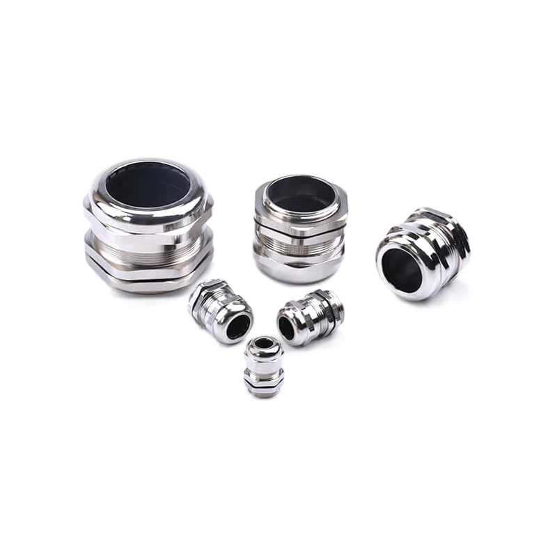
Cable gland material selection directly impacts earthing effectiveness—brass and stainless steel provide excellent conductivity and corrosion resistance, while nylon glands require separate earthing arrangements to maintain system safety.
Material properties affect not just initial earthing performance but long-term reliability under various environmental conditions.
Material Comparison for Earthing
| Material | Conductivity | Corrosion Resistance | Earthing Method | Best Applications |
|---|---|---|---|---|
| Brass (Nickel Plated) | Excellent | Good | Direct through body | General industrial, indoor |
| Stainless Steel 316L | Very Good | Excellent | Direct through body | Marine, chemical, outdoor |
| Nylon PA66 | Insulator | Excellent | Separate earth wire | Non-hazardous, cost-sensitive |
| Aluminum | Good | Fair | Direct through body | Lightweight applications |
Brass Gland Advantages: Nickel-plated brass offers excellent electrical conductivity and moderate corrosion resistance. The material provides reliable earthing through the gland body when properly installed with appropriate torque specifications.
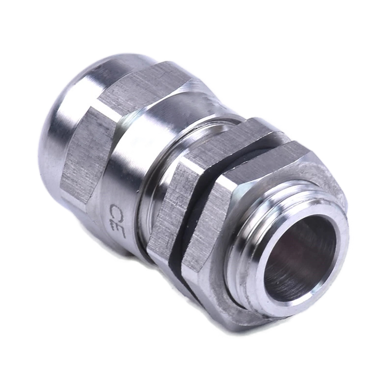
Stainless Steel Benefits: 316L stainless steel combines good conductivity with superior corrosion resistance. This makes it ideal for marine environments, chemical processing, and outdoor installations where long-term earthing reliability is critical.
Nylon Considerations: While nylon glands offer cost advantages and chemical resistance, their insulating properties require separate earthing arrangements. This typically involves dedicated earth wires connected to cable armor and earthing terminals.
Environmental Impact on Earthing
Corrosion Effects: Salt spray, chemical exposure, and galvanic corrosion can degrade earthing connections over time. Material selection must account for the specific environmental challenges in each installation.
Temperature Cycling: Thermal expansion and contraction can loosen earthing connections, particularly at dissimilar metal interfaces. Proper installation techniques and regular maintenance help maintain connection integrity.
Vibration and Movement: Industrial environments with significant vibration require enhanced connection methods, including spring washers, locking compounds, or specialized earthing braids that accommodate movement.
David, a project engineer from a wind farm operator in Denmark, learned about environmental effects firsthand when several turbine earthing connections failed after two years of coastal exposure. The combination of salt spray and thermal cycling had corroded standard connections. We provided marine-grade stainless steel glands with integrated earthing lugs and anti-seize compounds, eliminating the recurring failures.
What Are the Key Earthing and Bonding Requirements?
Earthing and bonding requirements encompass conductor sizing, connection resistance limits, continuity testing, and specific provisions for different installation types—all designed to ensure reliable fault current paths and equipment protection.
Meeting these requirements requires understanding both electrical theory and practical installation challenges.
Conductor Sizing Requirements
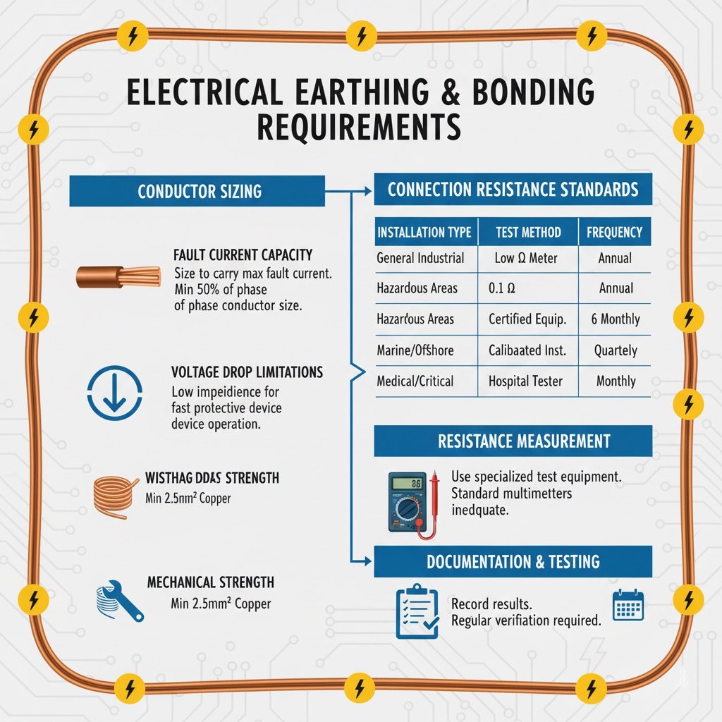
Fault Current Capacity: Earthing conductors must carry the maximum prospective fault current without damage. This typically requires conductors sized at minimum 50% of the phase conductor cross-sectional area, with larger sizes for high fault current installations.
Voltage Drop Limitations: Earth fault loop impedance4 must be low enough to ensure protective devices operate within required time limits. This often drives conductor sizing beyond minimum current-carrying requirements.
Mechanical Strength: Earthing conductors must withstand mechanical stresses during installation and operation. Minimum sizes (typically 2.5mm² copper) ensure adequate mechanical integrity regardless of electrical requirements.
Connection Resistance Standards
| Installation Type | Maximum Resistance | Test Method | Frequency |
|---|---|---|---|
| General Industrial | 0.1 ohms | Low resistance ohmmeter5 | Annual |
| Hazardous Areas | 0.1 ohms | Certified test equipment | 6 months |
| Marine/Offshore | 0.05 ohms | Calibrated instruments | Quarterly |
| Medical/Critical | 0.05 ohms | Hospital-grade testers | Monthly |
Resistance Measurement: Connection resistance must be measured using appropriate test equipment capable of detecting small resistance values. Standard multimeters are inadequate for this purpose.
Documentation Requirements: All earthing measurements must be recorded and maintained for regulatory compliance and maintenance planning. Many jurisdictions require certified test reports from qualified personnel.
Periodic Testing: Earthing systems require regular testing to verify continued effectiveness. Test frequencies depend on installation criticality and environmental conditions.
Bonding Continuity Requirements
Equipment Bonding: All metallic equipment within the installation must be bonded to the earthing system through low-resistance connections. This includes cable glands, enclosures, cable trays, and structural steelwork.
Armor Termination: Cable armor must be properly terminated at both ends with appropriate earthing connections. This requires specialized glands or termination kits designed for armored cable applications.
Explosion-Proof Bonding: Hazardous area installations require enhanced bonding with specific resistance limits (typically 0.1 ohms maximum) and certified connection methods.
How to Install Proper Earthing Connections?
Proper earthing installation requires clean connections, appropriate torque specifications, corrosion protection, and systematic testing to ensure long-term reliability and safety compliance.
Installation quality directly affects system safety and long-term maintenance requirements.
Connection Preparation
Surface Preparation: All connection surfaces must be clean and free from paint, oxidation, or contamination. Use wire brushes, emery cloth, or chemical cleaners as appropriate for the materials involved.
Torque Specifications: Follow manufacturer torque requirements precisely. Under-tightening creates high-resistance connections, while over-tightening can damage threads or crush sealing materials.
Anti-Seize Application: Use appropriate anti-seize compounds on threaded connections to prevent galling and facilitate future maintenance. Choose compounds compatible with the materials and environmental conditions.
Installation Best Practices
Connection Sequence: Install earthing connections before energizing circuits. This ensures personnel safety and prevents equipment damage if faults occur during installation.
Multiple Connection Points: Use multiple earthing connections where possible to provide redundancy and reduce overall system resistance. This is particularly important for critical installations.
Cable Management: Route earthing conductors to minimize mechanical stress and avoid sharp edges or pinch points. Secure conductors properly to prevent movement during operation.
Environmental Protection: Protect connections from moisture, chemicals, and physical damage using appropriate covers, sealing compounds, or protective enclosures.
Testing and Verification
Hassan, who manages a petrochemical complex in Kuwait, emphasizes the importance of systematic testing after experiencing an explosion-proof equipment failure due to inadequate bonding. His facility now requires comprehensive earthing tests using calibrated equipment, with results documented in a computerized maintenance system. This systematic approach has eliminated bonding-related incidents and improved regulatory compliance.
Initial Testing: Perform comprehensive resistance measurements on all earthing connections before system commissioning. Document results and compare against applicable standards.
Periodic Verification: Establish regular testing schedules based on installation criticality and environmental conditions. More frequent testing may be required for harsh environments or critical applications.
Fault Investigation: When protective devices operate unexpectedly, verify earthing system integrity as part of the investigation process. Poor earthing connections can cause nuisance trips or prevent proper fault clearing.
What Common Earthing Mistakes Should You Avoid?
The most critical earthing mistakes include inadequate conductor sizing, poor connection quality, mixing incompatible materials, and neglecting long-term maintenance—all of which can compromise system safety and reliability.
Learning from common mistakes helps prevent costly failures and safety incidents.
Critical Installation Errors
Inadequate Conductor Sizing: Using undersized earthing conductors creates high-resistance paths that may not carry fault currents safely. Always verify conductor sizing against fault current calculations and applicable standards.
Poor Connection Quality: Loose, corroded, or contaminated connections create high-resistance paths that compromise earthing effectiveness. Proper surface preparation and torque application are essential.
Material Incompatibility: Mixing dissimilar metals without proper precautions creates galvanic corrosion that degrades connections over time. Use appropriate transition materials or protective coatings when necessary.
Inadequate Environmental Protection: Failing to protect connections from moisture, chemicals, or physical damage leads to premature failure and safety hazards.
System Design Errors
Single Point Failures: Relying on single earthing connections without redundancy creates vulnerability to connection failures. Design systems with multiple earthing paths where possible.
Inadequate Testing Access: Installing earthing connections in locations that prevent easy testing and maintenance creates long-term reliability problems. Plan for accessibility during design phases.
Ignoring Thermal Effects: Failing to account for thermal expansion and contraction can loosen connections over time. Use appropriate connection methods for temperature cycling environments.
Documentation Deficiencies: Poor documentation makes troubleshooting difficult and compromises maintenance effectiveness. Maintain accurate records of all earthing connections and test results.
Maintenance Oversights
Irregular Testing: Skipping scheduled earthing tests allows problems to develop undetected. Maintain consistent testing schedules based on installation requirements.
Ignoring Environmental Changes: Changes in installation environment (new chemicals, temperature ranges, etc.) may require earthing system modifications. Regular system reviews help identify necessary updates.
Inadequate Training: Personnel without proper earthing knowledge may create safety hazards during maintenance activities. Ensure all personnel understand earthing principles and safety requirements.
Conclusion
Proper cable gland earthing and bonding forms the foundation of electrical system safety, providing essential fault current paths and equipment protection. Success requires understanding material properties, regulatory requirements, and proper installation techniques while avoiding common mistakes that compromise system integrity.
The key to effective earthing lies in systematic design, quality installation, and regular maintenance verification. At Bepto, our comprehensive range of cable glands includes specialized earthing features designed for various applications, from basic industrial installations to demanding offshore and hazardous area environments. With proper specification, installation, and maintenance, these systems provide the reliable earthing performance essential for electrical safety and regulatory compliance.
FAQs About Cable Gland Earthing and Bonding
Q: What size earthing conductor do I need for cable glands?
A: Earthing conductor size depends on fault current levels and protective device characteristics, typically minimum 2.5mm² copper for mechanical strength, with larger sizes required for high fault current installations. Consult applicable electrical codes for specific requirements.
Q: Can I use nylon cable glands in earthed systems?
A: Yes, but nylon glands require separate earthing arrangements since the material is non-conductive. Install dedicated earth wires connected to cable armor and earthing terminals to maintain system earthing integrity.
Q: How often should cable gland earthing connections be tested?
A: Testing frequency depends on installation type and environment – annually for general industrial, every 6 months for hazardous areas, and quarterly for marine applications. Critical installations may require more frequent testing.
Q: What’s the maximum allowable resistance for earthing connections?
A: Most standards specify 0.1 ohms maximum resistance for earthing connections, with some critical applications requiring 0.05 ohms or less. Always verify against applicable local codes and standards for your specific installation.
Q: Do stainless steel cable glands provide adequate earthing?
A: Yes, 316L stainless steel glands provide good electrical conductivity for earthing applications while offering superior corrosion resistance. Ensure proper installation torque and use anti-seize compounds to maintain long-term connection integrity.
-
Learn about the operating principles of circuit breakers and how they protect electrical circuits from overcurrents. ↩
-
Review the scope of the International Electrotechnical Commission’s fundamental standard for the safety of electrical installations. ↩
-
Explore the requirements of the UK’s national standard for electrical installation and safety. ↩
-
Understand this critical parameter for verifying the safety of an electrical installation and ensuring proper protective device operation. ↩
-
Discover the principles of four-wire Kelvin measurement used in microhmmeters to accurately test low electrical resistances. ↩
