Introduction
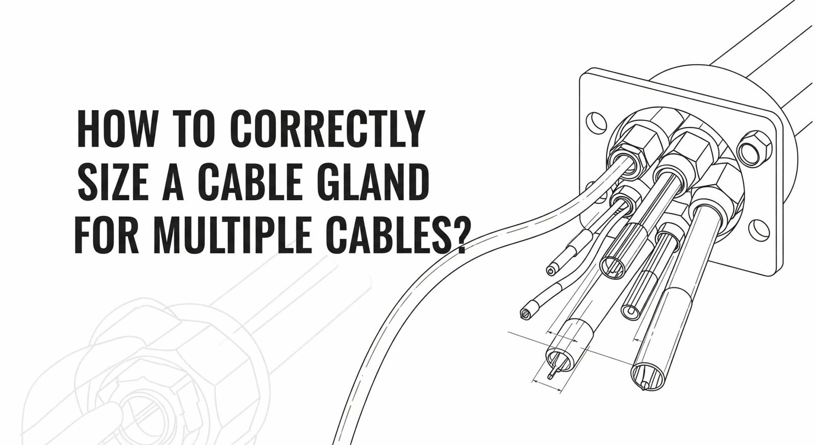
Are you struggling with cable gland sizing for multi-cable installations? Getting the size wrong can lead to poor sealing, cable damage, or complete installation failure – problems that cost thousands in rework and downtime. Many engineers face this challenge when dealing with control panels, junction boxes, or equipment requiring multiple cable entries through a single gland.
To correctly size a cable gland for multiple cables, calculate the total cross-sectional area of all cables, add 15-20% clearance for proper sealing compression, then select a gland with an internal diameter that accommodates this total area while maintaining IP rating1 integrity. The key is balancing adequate space for all cables with sufficient compression for environmental sealing.
As Sales Director at Bepto Connector, I’ve helped countless engineers solve multi-cable sizing challenges across industries. Just last month, Marcus from a major automotive plant in Stuttgart contacted us after his team’s incorrect sizing led to water ingress that damaged €50,000 worth of control equipment. His experience – and our proven sizing methodology – will help you avoid similar costly mistakes.
Table of Contents
- What Are the Key Factors in Multi-Cable Gland Sizing?
- How Do You Calculate Total Cable Area for Gland Selection?
- What Are the Different Multi-Cable Gland Types and When to Use Each?
- How Do You Ensure Proper Sealing with Multiple Cables?
- What Are Common Multi-Cable Sizing Mistakes to Avoid?
- FAQs About Multi-Cable Gland Sizing
What Are the Key Factors in Multi-Cable Gland Sizing?
Multi-cable gland sizing requires careful consideration of cable diameters, sealing requirements, environmental conditions, and installation constraints to ensure reliable long-term performance. Understanding these factors prevents sizing errors that compromise system integrity.
Cable Diameter Variations
Individual Cable Measurements
Each cable in your installation may have different outer diameters depending on insulation thickness, shielding, and conductor count. Accurate measurement of each cable’s outer diameter is critical – don’t rely on catalog specifications alone, as manufacturing tolerances can vary significantly.
Cable Flexibility Considerations
Flexible cables compress more easily during installation, while rigid cables maintain their shape. This affects how tightly cables can be packed within the gland and influences the minimum gland size required for proper installation.
Environmental Sealing Requirements
IP Rating Maintenance
Multi-cable installations must maintain the required IP rating despite having multiple penetrations through the sealing element. Higher IP ratings (IP67, IP68) require tighter sealing compression, which may necessitate larger gland sizes to accommodate the same number of cables.
Temperature and Chemical Resistance
Operating environment affects both cable expansion and sealing material performance. High-temperature applications cause cable expansion, requiring additional clearance, while chemical exposure demands specific elastomer materials that may have different compression characteristics.
Marcus from Stuttgart learned this lesson the hard way. His initial calculations didn’t account for temperature expansion in their paint booth environment, where cables heated to 80°C expanded beyond the gland’s sealing capacity. “We had perfect fit at room temperature,” he explained, “but summer heat caused seal failure and water damage to our control systems.”
Installation Accessibility
Space Constraints
Available space around the gland location affects both gland size selection and cable routing. Tight spaces may require smaller glands with fewer cables per gland, or specialized low-profile designs that accommodate multiple cables in confined areas.
Maintenance Access
Consider future cable additions or replacements when sizing glands. Oversizing slightly can accommodate future expansion without requiring complete gland replacement, saving significant labor costs in retrofit situations.
At Bepto, our multi-cable glands incorporate advanced sealing designs that maintain IP ratings across wide temperature ranges. Our ISO9001-certified2 manufacturing ensures consistent quality, while our extensive testing validates performance with various cable combinations and environmental conditions.
How Do You Calculate Total Cable Area for Gland Selection?
Accurate area calculation involves measuring individual cable diameters, calculating cross-sectional areas, summing the total, and adding appropriate clearance factors for sealing compression and installation tolerances. This systematic approach ensures proper gland sizing every time.
Step-by-Step Calculation Method
Step 1: Measure Individual Cable Diameters
Use calipers3 to measure the outer diameter of each cable at multiple points, as cables may not be perfectly round. Record the maximum diameter for each cable to ensure adequate clearance.
Step 2: Calculate Individual Cross-Sectional Areas
For each cable, calculate the area using the formula: Area = π × (diameter/2)²
Example: 12mm diameter cable = π × (12/2)² = π × 36 = 113.1 mm²
Step 3: Sum Total Cable Area
Add all individual cable areas to get the total cross-sectional area occupied by cables.
Example: Three cables (12mm, 8mm, 6mm) = 113.1 + 50.3 + 28.3 = 191.7 mm²
Step 4: Apply Clearance Factors
Add clearance for proper sealing compression:
- Standard applications: 15-20% clearance
- High IP rating requirements: 20-25% clearance
- Difficult installation conditions: 25-30% clearance
Step 5: Select Appropriate Gland Size
Choose a gland with internal sealing diameter that accommodates the calculated total area.
Practical Calculation Example
Hassan, who manages a petrochemical facility in Dubai, recently needed to size glands for a multi-cable installation with:
- 2 × 16mm power cables
- 3 × 10mm control cables
- 2 × 6mm signal cables
Calculation Process:
- 16mm cables: 2 × π × 8² = 2 × 201.1 = 402.2 mm²
- 10mm cables: 3 × π × 5² = 3 × 78.5 = 235.6 mm²
- 6mm cables: 2 × π × 3² = 2 × 28.3 = 56.6 mm²
- Total cable area: 694.4 mm²
- With 20% clearance: 694.4 × 1.2 = 833.3 mm²
- Required gland diameter: √(833.3/π) × 2 = 32.5mm
Hassan selected our M40 multi-cable gland (internal diameter 34mm) which provided perfect fit with proper sealing compression for his IP67 requirements.
Cable Packing Efficiency
Theoretical vs. Practical Packing
While mathematical calculations provide the minimum area required, practical cable installation rarely achieves perfect packing efficiency. Cables naturally form irregular patterns with air gaps, requiring additional clearance beyond theoretical calculations.
Packing Factor4 Guidelines
- Round cables of similar size: 85-90% packing efficiency
- Mixed cable sizes: 75-85% packing efficiency
- Irregular cable shapes: 70-80% packing efficiency
Apply these factors by dividing your calculated cable area by the appropriate packing efficiency to determine the actual gland area required.
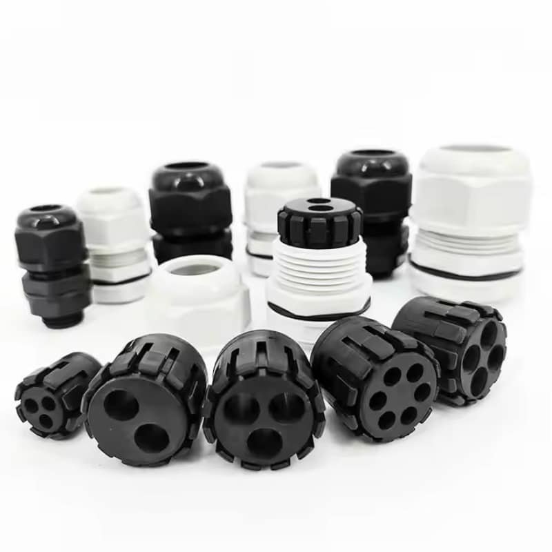
What Are the Different Multi-Cable Gland Types and When to Use Each?
Multi-cable glands come in several designs including split-body types, insert-based systems, and modular configurations, each optimized for specific installation requirements and cable combinations. Choosing the right type ensures optimal performance and installation efficiency.
Split-Body Multi-Cable Glands
Design Characteristics
Split-body glands feature removable top sections that allow cable installation without disconnecting cable ends. This design significantly simplifies installation in retrofit applications where cables are already terminated.
Optimal Applications
- Retrofit installations with existing cable terminations
- Maintenance applications requiring frequent cable access
- Installations with limited space for cable maneuvering
- Applications requiring IP65-IP67 protection levels
Performance Considerations
Split-body designs typically achieve slightly lower IP ratings than solid-body alternatives due to additional sealing interfaces. However, premium designs with O-ring seals can achieve IP67 ratings suitable for most industrial applications.
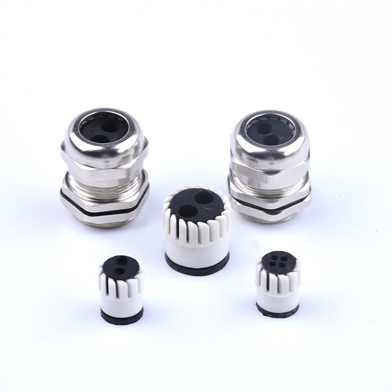
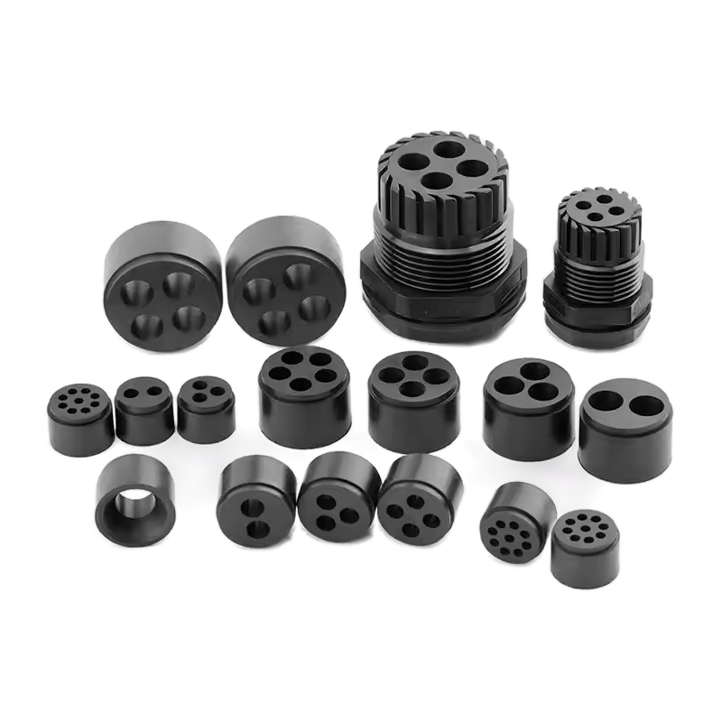
Insert-Based Gland Systems
Modular Sealing Approach
Insert-based systems use removable sealing inserts with pre-formed holes for specific cable combinations. Multiple insert options allow customization for different cable arrangements while maintaining consistent gland body sizes.
Key Advantages
- Standardized gland bodies reduce inventory requirements
- Interchangeable inserts accommodate different cable combinations
- Excellent sealing performance with proper insert selection
- Cost-effective for installations with varying cable requirements
Selection Criteria
Choose insert-based systems when you need flexibility for different cable combinations or when standardizing on common gland body sizes provides inventory advantages.
Solid-Body Multi-Cable Glands
Maximum Performance Design
Solid-body glands provide the highest IP ratings and most robust sealing performance through unified construction without additional sealing interfaces. These glands excel in demanding environmental conditions.
Application Focus
- Marine and offshore installations requiring IP68 ratings
- Chemical processing with aggressive media exposure
- Outdoor installations facing extreme weather conditions
- Critical applications where maximum reliability is essential
Installation Requirements
Solid-body glands require cable installation before final termination, making them ideal for new installations but challenging for retrofit applications.
Gland Type Selection Matrix
| Application | Recommended Type | IP Rating | Key Benefits |
|---|---|---|---|
| New Installation | Solid-Body | IP68 | Maximum sealing, lowest cost |
| Retrofit Project | Split-Body | IP67 | Easy installation, cable access |
| Variable Cables | Insert-Based | IP67 | Flexibility, standardization |
| Marine/Offshore | Solid-Body Stainless | IP68 | Corrosion resistance, reliability |
| Control Panels | Insert-Based | IP65-IP67 | Clean appearance, modularity |
At Bepto, we manufacture all three gland types with consistent quality standards and interchangeable threading systems. Our modular approach allows customers to standardize on thread sizes while selecting optimal sealing methods for each application.
How Do You Ensure Proper Sealing with Multiple Cables?
Proper sealing with multiple cables requires careful attention to compression uniformity, sealing material selection, and installation procedures that maintain consistent pressure around all cable penetrations. Achieving reliable sealing with varying cable sizes presents unique challenges.
Compression Uniformity Challenges
Varying Cable Diameters
When cables of different sizes pass through the same gland, the sealing element must compress uniformly around each cable despite diameter variations. This requires specialized sealing designs that accommodate mixed cable sizes while maintaining consistent compression pressure.
Sealing Element Design
Advanced multi-cable glands use graduated sealing elements or multiple compression zones that adapt to different cable diameters. These designs ensure adequate compression on smaller cables while preventing over-compression of larger ones.
Material Selection for Multi-Cable Applications
Elastomer Flexibility Requirements
Multi-cable applications demand sealing materials with excellent flexibility and recovery properties. The elastomer must conform to irregular cable arrangements while maintaining sealing integrity across temperature and pressure variations.
Temperature Stability
Different cables may generate varying amounts of heat, creating temperature gradients within the gland. Sealing materials must maintain properties across these temperature variations to prevent localized seal failure.
Chemical Compatibility Matrix
| Environment | Recommended Elastomer | Temperature Range | Key Properties |
|---|---|---|---|
| Standard Industrial | NBR (Nitrile) | -20°C to +80°C | Oil resistance, cost-effective |
| High Temperature | FKM (Viton) | -20°C to +150°C | Excellent heat resistance |
| Chemical Processing | EPDM | -40°C to +120°C | Broad chemical compatibility |
| Food/Pharma | FDA Silicone | -50°C to +180°C | Non-toxic, easy cleaning |
Installation Best Practices
Cable Preparation
Remove sharp edges, burrs, or cable tie remnants that could damage sealing elements during installation. Ensure cable jackets are clean and free from oils or contaminants that might affect seal adhesion.
Compression Torque Guidelines
Apply compression gradually and evenly to prevent seal distortion. Over-tightening can cause seal extrusion or uneven compression, while under-tightening compromises environmental protection.
Verification Procedures
After installation, verify sealing integrity through appropriate testing methods such as pressure testing for IP67/IP68 applications or visual inspection for standard industrial installations.
Marcus from Stuttgart now follows our recommended installation procedures religiously. “The step-by-step compression sequence you provided eliminated our sealing problems completely,” he reported. “We haven’t had a single seal failure since implementing your guidelines six months ago.”
What Are Common Multi-Cable Sizing Mistakes to Avoid?
Common sizing mistakes include inadequate clearance calculations, ignoring temperature expansion, mixing incompatible cable types, and failing to consider long-term maintenance requirements. Learning from these errors prevents costly installation problems and system failures.
Mistake 1: Insufficient Clearance Calculation
The Problem
Many engineers calculate exact cable areas without adequate clearance for sealing compression, installation tolerances, or thermal expansion. This results in glands that appear correctly sized but fail to achieve proper sealing or allow adequate cable movement.
Real-World Consequences
- Difficulty during cable installation
- Poor sealing performance and IP rating failures
- Cable jacket damage from excessive compression
- Premature seal failure due to over-stress
Prevention Strategy
Always add minimum 15-20% clearance to calculated cable areas, with additional margin for high-temperature applications or critical sealing requirements. When in doubt, test-fit cables in sample glands before finalizing specifications.
Mistake 2: Ignoring Cable Type Compatibility
The Problem
Mixing power cables with sensitive signal cables in the same gland can cause electromagnetic interference5, while combining cables with different temperature ratings may compromise system safety.
Technical Issues
- EMI from power cables affecting signal integrity
- Heat transfer between cables causing insulation degradation
- Different expansion rates creating mechanical stress
- Chemical incompatibility between cable jacket materials
Best Practice Solution
Group compatible cables together and use separate glands for different cable types when necessary. Consider EMC-rated glands for installations mixing power and control cables.
Mistake 3: Overlooking Environmental Factors
Temperature Expansion Oversight
Hassan from Dubai initially sized glands based on room temperature cable measurements, not accounting for the 60°C operating temperatures in his facility. “Three months later, we had seal failures throughout the plant,” he explained. “The cables expanded beyond our gland capacity, compromising the IP67 rating we needed for washdown procedures.”
Humidity and Chemical Exposure
Failing to consider environmental conditions affects both cable properties and sealing material performance. High humidity can cause cable swelling, while chemical exposure may degrade certain elastomers.
Mistake 4: Inadequate Future Planning
No Provision for Cable Additions
Sizing glands exactly for current cable requirements leaves no room for future system expansions or cable replacements. This short-sighted approach often requires complete gland replacement when modifications are needed.
Maintenance Access Limitations
Choosing the smallest possible gland size may complicate future maintenance or cable replacement procedures, increasing long-term labor costs despite initial material savings.
Strategic Sizing Approach
Consider sizing glands 25-30% larger than immediate requirements when space permits. This modest oversizing accommodates future needs while maintaining proper sealing performance with current cable loads.
Mistake 5: Incorrect Gland Type Selection
Using Single-Cable Glands for Multiple Cables
Some installations attempt to use multiple single-cable glands instead of proper multi-cable designs. While this may seem cost-effective, it often results in higher total costs due to increased labor, more penetrations requiring sealing, and potential structural weakening of enclosures.
Ignoring Installation Constraints
Selecting solid-body glands for retrofit applications where cables cannot be disconnected creates unnecessary installation complexity and labor costs. Split-body or insert-based designs often provide better solutions for these situations.
At Bepto, we provide detailed sizing guides and application support to help customers avoid these common mistakes. Our technical team reviews critical applications to ensure optimal gland selection and sizing for each specific requirement.
Conclusion
Correctly sizing cable glands for multiple cables requires systematic calculation of cable areas, proper clearance factors, and careful consideration of environmental conditions and installation requirements. The key is balancing adequate space for all cables with sufficient compression for reliable environmental sealing.
Success depends on accurate measurements, appropriate clearance calculations, and selecting the right gland type for your specific application. While the process may seem complex, following proven methodologies prevents costly sizing errors that compromise system performance and reliability.
At Bepto Connector, our comprehensive range of multi-cable glands provides solutions for every application, from standard industrial installations to demanding marine and chemical processing environments. Our ISO9001 and TUV certifications ensure consistent quality, while our technical support team helps customers achieve optimal sizing and selection for their specific requirements.
Remember: proper gland sizing is an investment in system reliability. Take time to calculate accurately, consider all environmental factors, and choose quality glands that will deliver years of trouble-free performance. The extra effort in planning prevents expensive problems down the road.
FAQs About Multi-Cable Gland Sizing
Q: How do I calculate the right size gland for cables of different diameters?
A: Calculate each cable’s cross-sectional area using π × (diameter/2)², sum all areas, then add 15-20% clearance for sealing compression. Select a gland with internal diameter accommodating this total area while maintaining required IP rating.
Q: Can I use one large gland instead of multiple smaller ones for several cables?
A: Yes, when properly sized, one multi-cable gland often provides better sealing, lower cost, and fewer enclosure penetrations than multiple single-cable glands. However, consider cable compatibility and future maintenance access when making this decision.
Q: What’s the maximum number of cables I can put through one gland?
A: There’s no fixed limit – it depends on individual cable sizes, gland diameter, and sealing requirements. The key is ensuring adequate compression around each cable while maintaining the required IP rating and allowing proper installation clearance.
Q: Do I need different gland types for power and control cables together?
A: For most applications, standard multi-cable glands work fine. However, if you’re mixing high-power cables with sensitive signals, consider EMC-rated glands to prevent electromagnetic interference, or use separate glands for different cable types.
Q: How much extra space should I allow for thermal expansion of cables?
A: Add 5-10% extra clearance for standard temperature applications, and 15-20% for high-temperature environments above 60°C. Consider both cable expansion and potential compression of sealing materials when calculating total clearance requirements.
-
Learn about the international standard for Ingress Protection (IP) ratings to understand how enclosures are classified against solids and liquids. ↩
-
Explore the fundamentals of the ISO 9001 standard, the global benchmark for quality management systems. ↩
-
Read a practical guide on how to use digital calipers to achieve precise and repeatable diameter measurements. ↩
-
Delve into the mathematical principles of circle packing, which explains the efficiency of fitting multiple round cables into a single circular opening. ↩
-
Understand the basics of Electromagnetic Interference (EMI) and how it can disrupt the performance of sensitive electronic signals. ↩
