
Managing electrical safety in industrial facilities? One grounding failure can turn routine maintenance into a fatal accident.
Proper electrical bonding and grounding through cable glands provides critical protection against electrical shock, equipment damage, and fire hazards – inadequate grounding systems cause over 200 workplace fatalities and thousands of injuries annually in industrial settings.
This morning, Sarah, a safety officer at a chemical processing plant, called me shaken after a near-miss incident. A contractor received a severe electrical shock when touching an improperly grounded control panel during routine maintenance. The investigation revealed corroded cable gland connections had compromised the entire grounding system. Only the quick response of nearby workers prevented a fatality.
Table of Contents
- Why Electrical Bonding and Grounding Are Critical for Industrial Safety?
- How Do Cable Glands Ensure Proper Electrical Continuity?
- What Are the Essential Installation and Testing Requirements?
- How Do You Maintain Long-Term Grounding System Integrity?
Why Electrical Bonding and Grounding Are Critical for Industrial Safety?
Understanding grounding principles isn’t just technical knowledge – it’s the foundation of electrical safety that protects lives and prevents catastrophic accidents.
Electrical grounding1 provides a safe path for fault currents to flow to earth, while bonding ensures all metallic components maintain the same electrical potential, preventing dangerous voltage differences that can cause shock, fire, or explosion.
Fundamental Safety Principles
Grounding System Functions:
Fault Current Path:
When electrical insulation fails, grounding systems provide a low-resistance path for fault current to flow safely to earth, enabling protective devices to operate quickly and disconnect power.
Voltage Stabilization:
Grounding establishes a reference point (zero volts) for electrical systems, preventing dangerous voltage buildup on equipment enclosures and metallic structures.
Lightning Protection:
Proper grounding systems safely dissipate lightning strikes and electrical surges, protecting both equipment and personnel from dangerous overvoltages.
Static Electricity Dissipation:
In industrial environments, grounding prevents static electricity buildup that could cause fires, explosions, or equipment damage.
Bonding vs. Grounding Distinction
Electrical Bonding:
- Connects metallic components to ensure equal electrical potential
- Prevents voltage differences between adjacent metal surfaces
- Creates continuous electrical paths through equipment
- Eliminates shock hazards from potential differences
Electrical Grounding:
- Connects electrical systems to earth through grounding electrodes
- Provides fault current return path to source
- Establishes system voltage reference point
- Enables protective device operation
Critical Integration:
Both bonding and grounding must work together – bonding without grounding leaves systems “floating,” while grounding without bonding creates potential differences between components.
Industrial Hazard Categories
Electrical Shock Hazards:
Direct Contact:
- Contact with energized conductors
- Insulation failure exposing live parts
- Improper work procedures on energized equipment
- Inadequate personal protective equipment
Indirect Contact:
- Touching metal enclosures energized by faults
- Step and touch potentials2 near grounding systems
- Voltage differences between bonded components
- Static electricity discharge
Arc Flash and Blast Hazards:
Arc Flash Causes:
- Ground faults in poorly grounded systems
- Phase-to-ground faults with high impedance paths
- Equipment failure due to inadequate grounding
- Maintenance work on improperly grounded systems
Protection Requirements:
- Low-impedance grounding paths for rapid fault clearing
- Proper coordination of protective devices
- Arc flash hazard analysis and labeling
- Personal protective equipment requirements
Real-World Consequences
Sarah’s chemical plant incident demonstrates the life-threatening consequences of grounding failures:
Initial Conditions:
- 480V motor control center with corroded cable gland connections
- Moisture ingress had compromised grounding continuity
- Visual inspection hadn’t detected the internal corrosion
- No recent grounding system testing performed
Fault Sequence:
- Motor insulation failure created phase-to-ground fault
- High-resistance grounding path couldn’t carry fault current
- Control panel enclosure became energized at 240V
- Contractor contacted energized surface during maintenance
- Fault current flowed through worker’s body to ground
Contributing Factors:
- Inadequate grounding system maintenance
- Missing periodic testing and inspection
- Corroded cable gland connections
- Insufficient bonding between panel sections
Preventive Measures Implemented:
- Complete grounding system inspection and testing
- Cable gland replacement with corrosion-resistant materials
- Enhanced maintenance procedures and schedules
- Worker training on electrical safety procedures
Regulatory and Standard Requirements
OSHA Requirements (29 CFR 1910.304):
Grounding System Standards:
- Equipment grounding conductor requirements
- Grounding electrode system specifications
- Bonding requirements for metallic components
- Testing and maintenance obligations
NFPA 70 (National Electrical Code):
Article 250 – Grounding and Bonding3:
- System grounding requirements
- Equipment grounding specifications
- Grounding electrode systems
- Bonding of metallic components
International Standards:
IEC 60364 – Electrical Installations:
- Earthing system classifications (TN, TT, IT)
- Protection against electric shock
- Equipotential bonding requirements
- Installation and testing procedures
Industry-Specific Considerations
Hazardous Locations:
- Enhanced bonding requirements for explosion prevention
- Intrinsically safe system grounding
- Static electricity control measures
- Special grounding for flammable atmospheres
Marine and Offshore:
- Cathodic protection system integration
- Saltwater environment corrosion concerns
- Lightning protection for exposed structures
- Isolation transformer grounding systems
Data Centers and IT Facilities:
- Signal reference grounding for equipment protection
- Power quality and electromagnetic compatibility
- Isolated grounding for sensitive equipment
- Surge protection device coordination
How Do Cable Glands Ensure Proper Electrical Continuity?
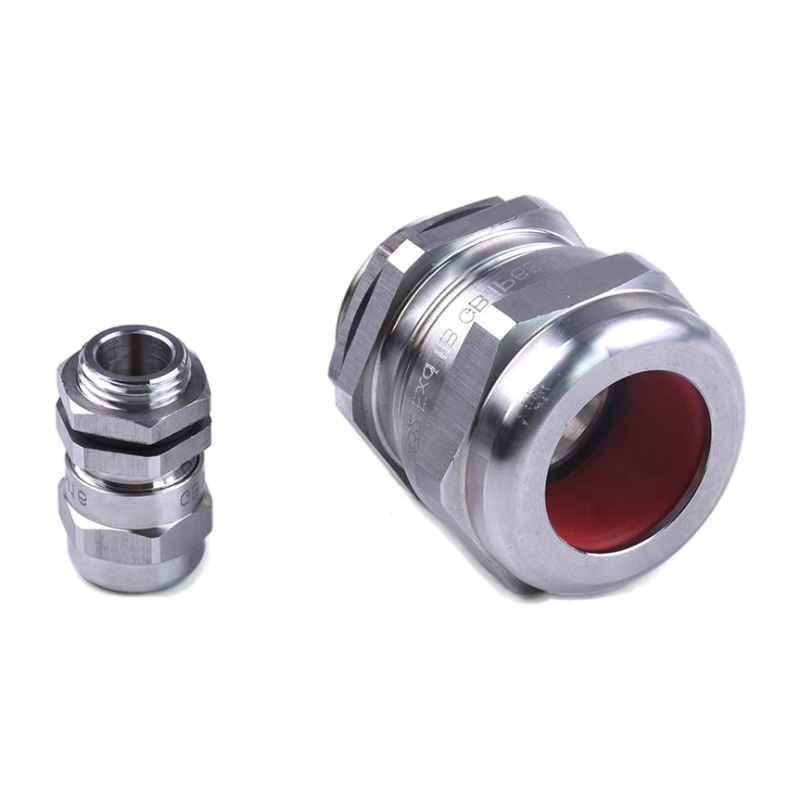
Cable glands are critical components in maintaining grounding system integrity – improper selection or installation can create dangerous high-resistance connections.
Cable glands provide electrical continuity through direct metal-to-metal contact between cable armor, gland body, and equipment enclosure, while maintaining environmental sealing and mechanical cable retention under all operating conditions.
Cable Gland Grounding Mechanisms
Armored Cable Systems:
Steel Wire Armor (SWA):
- Continuous metallic path from source to load
- Cable gland clamps armor to provide grounding connection
- Multiple wire strands create redundant current paths
- Corrosion protection maintains long-term continuity
Aluminum Wire Armor (AWA):
- Lighter weight alternative to steel armor
- Requires compatible aluminum-rated cable glands
- Galvanic corrosion prevention between dissimilar metals
- Enhanced conductivity compared to steel armor
Braided Shield Systems:
- Flexible metallic braid over cable core
- High-frequency noise immunity
- Requires proper termination for grounding effectiveness
- Special glands designed for braid termination
Grounding Connection Methods
Direct Armor Termination:
Compression-Type Glands:
- Mechanical compression clamps armor to gland body
- Metal-to-metal contact ensures low resistance
- Uniform pressure distribution prevents hot spots
- Weather sealing maintains connection integrity
Barrier-Type Glands:
- Physical barrier prevents armor strand movement
- Consistent termination under vibration
- Enhanced pull-out strength
- Suitable for high-stress applications
Indirect Grounding Methods:
Separate Grounding Conductors:
- Independent equipment grounding conductor (EGC)
- Terminated at dedicated grounding terminal
- Backup protection if armor continuity fails
- Required for non-metallic cable systems
Bonding Jumpers:
- External connection between gland and enclosure
- Provides redundant grounding path
- Accommodates thermal expansion differences
- Facilitates testing and maintenance
Material Selection for Grounding
Conductive Materials:
Brass Alloys:
- Excellent electrical conductivity
- Corrosion resistance in most environments
- Compatible with copper and aluminum conductors
- Available in lead-free formulations for RoHS compliance
Stainless Steel:
- Superior corrosion resistance
- Mechanical strength for harsh environments
- Lower conductivity than brass but adequate for grounding
- Non-magnetic grades available for special applications
Aluminum Alloys:
- Lightweight for weight-sensitive applications
- Good conductivity and corrosion resistance
- Requires proper surface treatment
- Compatible with aluminum cable armor
Plating and Surface Treatments:
Nickel Plating:
- Enhanced corrosion protection
- Maintains conductivity over time
- Compatible with most cable materials
- Standard treatment for marine applications
Tin Plating:
- Prevents oxidation of base metals
- Excellent solderability if required
- Cost-effective protection method
- Suitable for most industrial environments
Environmental Considerations
Corrosion Prevention:
Galvanic Compatibility:
- Matching gland material to cable armor
- Avoiding dissimilar metal combinations
- Using isolation washers when necessary
- Applying protective coatings
Moisture Protection:
- Environmental sealing prevents water ingress
- Corrosion-resistant materials and treatments
- Proper drainage and ventilation design
- Regular inspection and maintenance
Temperature Effects:
Thermal Expansion:
- Different expansion rates can stress connections
- Flexible connection design accommodates movement
- Spring-loaded terminals maintain contact pressure
- Temperature cycling testing validates performance
High-Temperature Applications:
- Special alloys for elevated temperatures
- Enhanced oxidation resistance
- Thermal cycling durability
- Insulation material compatibility
Connection Resistance Requirements
Acceptable Resistance Values:
NFPA 70 Requirements:
- Equipment grounding conductor resistance ≤ 25 ohms
- Bonding jumper resistance ≤ 0.1 ohms
- Connection resistance ≤ 0.05 ohms
- Total path resistance enables protective device operation
Testing Standards:
- IEEE 142 – Grounding of Industrial and Commercial Power Systems
- IEEE 80 – Guide for Safety in AC Substation Grounding
- IEC 61936 – Power Installations Exceeding 1 kV AC
Measurement Techniques:
- Four-wire resistance measurement4 for accuracy
- AC impedance testing for frequency effects
- Ground fault current testing
- Touch and step potential measurements
At Bepto, our cable glands are designed and tested to provide reliable grounding connections with resistance values well below industry requirements, ensuring long-term electrical safety and system integrity.
What Are the Essential Installation and Testing Requirements?
Proper installation and testing are critical for grounding system effectiveness – shortcuts in these areas can create life-threatening hazards.
Successful grounding installation requires proper cable preparation, correct torque application, environmental sealing verification, and comprehensive testing using calibrated instruments to verify resistance values and continuity under all operating conditions.
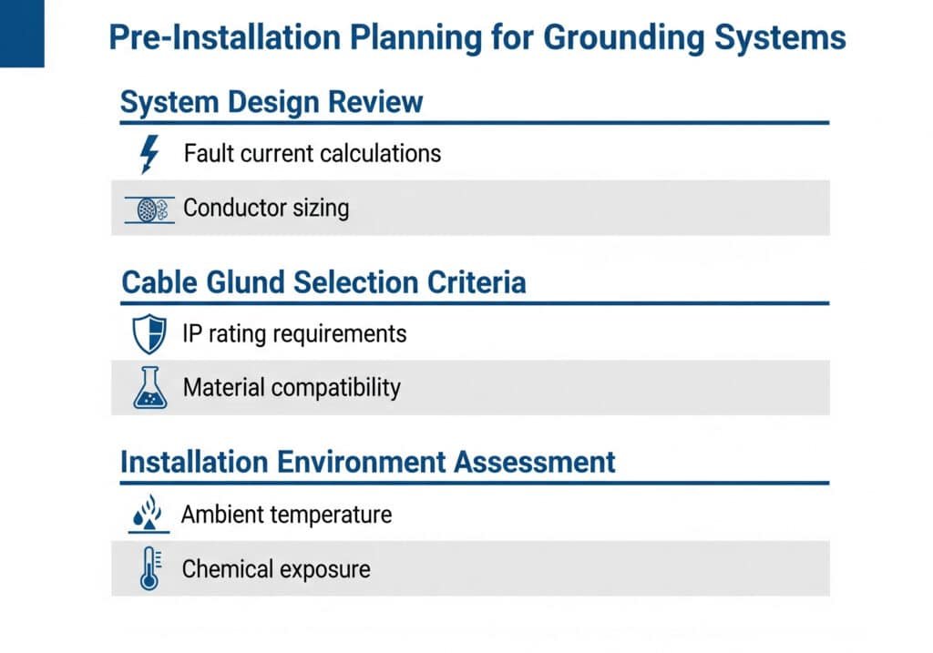
Pre-Installation Planning
System Design Review:
Grounding System Analysis:
- Single-line diagram review and verification
- Grounding electrode system adequacy
- Fault current calculations and protective device coordination
- Equipment grounding conductor sizing verification
- Bonding requirements identification
Cable Gland Selection Criteria:
- Cable type and armor construction compatibility
- Environmental conditions and IP rating requirements
- Current-carrying capacity and fault current ratings
- Material compatibility and corrosion resistance
- Mechanical strength and vibration resistance
Installation Environment Assessment:
- Ambient temperature ranges and thermal cycling
- Moisture, chemical, and UV exposure conditions
- Vibration and mechanical stress factors
- Accessibility for maintenance and testing
- Future expansion and modification requirements
Cable Preparation Procedures
Armored Cable Preparation:
Steel Wire Armor (SWA) Cables:
- Cable cutting: Use proper tools to prevent armor damage
- Armor stripping: Remove precise length for gland engagement
- Armor cleaning: Remove cutting oils and debris
- Strand separation: Ensure individual wire movement
- Core preparation: Strip insulation to required lengths
Aluminum Wire Armor (AWA) Cables:
- Special cutting tools: Prevent aluminum strand deformation
- Oxide removal: Clean aluminum surfaces for good contact
- Anti-oxidant compound: Apply to prevent future oxidation
- Gentle handling: Avoid breaking aluminum strands
- Immediate installation: Minimize exposure time
Braided Shield Cables:
- Braid preparation: Fold back over cable jacket
- Termination sleeve: Use proper connector for braid
- Contact pressure: Ensure uniform compression
- Shield continuity: Verify electrical connection
- Strain relief: Prevent braid damage from movement
Installation Best Practices
Mechanical Installation:
Torque Requirements:
- Follow manufacturer specifications exactly
- Use calibrated torque wrenches
- Apply torque in proper sequence
- Re-check after thermal cycling
- Document all torque values
Thread Engagement:
- Minimum 5 full threads for steel glands
- Use thread sealant appropriate for application
- Avoid over-tightening that damages threads
- Check for proper gasket compression
- Verify environmental sealing
Electrical Connection Verification:
Continuity Testing:
- Test cable armor continuity before installation
- Verify gland-to-enclosure connection
- Check end-to-end system continuity
- Test under mechanical stress
- Document all measurements
Resistance Measurement:
- Use four-wire measurement technique
- Test at multiple current levels
- Verify stability over time
- Compare to design requirements
- Record baseline values for future reference
Testing Procedures and Standards
Initial Acceptance Testing:
Insulation Resistance Testing:
- Test between conductors and ground
- Apply appropriate test voltages
- Meet minimum resistance requirements
- Test before and after installation
- Document environmental conditions
Ground Fault Current Testing:
- Verify protective device operation
- Measure actual fault current levels
- Check clearing times
- Validate coordination settings
- Test under various system conditions
Ongoing Testing Requirements:
Periodic Inspection Schedule:
- Visual inspection: Monthly or quarterly
- Resistance testing: Annually or bi-annually
- Thermal imaging: Annually for critical systems
- Mechanical integrity: During maintenance outages
- Documentation review: Continuous
Test Equipment Requirements:
Calibrated Instruments:
- Digital multimeters with 0.1% accuracy
- Micro-ohmmeters for low-resistance measurements
- Insulation resistance testers (meggers)
- Ground fault current injection equipment
- Thermal imaging cameras
Common Installation Errors
From my experience helping Sarah and other safety officers investigate grounding failures, these installation errors cause the most problems:
Inadequate Cable Preparation:
- Insufficient armor stripping length
- Damaged armor strands during preparation
- Contaminated connection surfaces
- Improper core conductor preparation
- Missing anti-oxidant treatments
Incorrect Installation Procedures:
- Wrong torque values or sequences
- Inadequate thread engagement
- Damaged gaskets or seals
- Mixed material combinations
- Poor workmanship quality
Testing Shortcuts:
- Skipped continuity testing
- Inadequate resistance measurements
- Missing documentation
- Uncalibrated test equipment
- Incomplete test procedures
Documentation Requirements
Installation Records:
Required Documentation:
- Cable gland specification sheets
- Installation procedure compliance
- Torque value records
- Test results and measurements
- Material certificates and traceability
- Worker qualification records
Testing Documentation:
Test Report Contents:
- Test equipment calibration certificates
- Environmental conditions during testing
- Complete measurement data
- Pass/fail criteria and results
- Corrective actions taken
- Inspector signatures and dates
Maintenance Records:
Ongoing Documentation:
- Periodic inspection results
- Resistance measurement trends
- Corrective maintenance actions
- Component replacement records
- System modification documentation
Quality Assurance Procedures
Installation Verification:
Multi-Point Inspection:
- Material verification against specifications
- Installation procedure compliance check
- Workmanship quality assessment
- Testing procedure verification
- Documentation completeness review
Independent Verification:
- Third-party inspection for critical systems
- Peer review of test results
- Supervisory approval of work
- Customer acceptance testing
- Regulatory inspection readiness
At Bepto, we provide comprehensive installation support including detailed procedures, training programs, and technical assistance to ensure proper grounding system installation and long-term reliability.
How Do You Maintain Long-Term Grounding System Integrity?
Grounding systems degrade over time without proper maintenance – what starts as a safe installation can become a deadly hazard.
Effective grounding maintenance requires regular visual inspections, periodic resistance testing, environmental monitoring, and proactive replacement of degraded components before they compromise system safety and reliability.
Degradation Mechanisms and Warning Signs
Corrosion-Related Failures:
- Occurs between dissimilar metals in presence of electrolyte
- Creates high-resistance connections over time
- Often hidden inside cable glands and connections
- Accelerated by moisture, salt, and chemical exposure
- Prevention requires material compatibility and protective coatings
Environmental Corrosion:
- General oxidation of metallic components
- Pitting corrosion in chloride environments
- Stress corrosion cracking under mechanical load
- Microbiologically influenced corrosion (MIC)
- UV degradation of protective coatings
Visual Warning Signs:
- Discoloration or staining around connections
- White, green, or rust-colored deposits
- Cracked or damaged protective coatings
- Loose or damaged hardware
- Evidence of moisture ingress
Mechanical Degradation:
Thermal Cycling Effects:
- Expansion and contraction stress connections
- Loosens threaded connections over time
- Causes fatigue cracking in materials
- Degrades gasket and seal materials
- Creates intermittent high-resistance connections
Vibration and Movement:
- Loosens mechanical connections
- Causes fretting corrosion at contact surfaces
- Breaks wire strands in cable armor
- Damages cable gland internal components
- Creates stress concentration points
Inspection Procedures and Frequency
Visual Inspection Protocols:
Monthly Inspections:
- Check for obvious corrosion or damage
- Verify environmental seal integrity
- Look for loose hardware or connections
- Check for proper cable support and strain relief
- Document any changes from previous inspections
Quarterly Detailed Inspections:
- Remove covers for internal component inspection
- Check torque on accessible connections
- Verify proper grounding conductor connections
- Inspect cable armor condition
- Test environmental sealing effectiveness
Annual Comprehensive Inspections:
- Complete system documentation review
- Thermal imaging of all connections
- Detailed resistance measurements
- Mechanical integrity testing
- Environmental condition assessment
Testing and Measurement Programs
Resistance Testing Requirements:
Test Frequency:
- Critical safety systems: Semi-annually
- General industrial equipment: Annually
- Non-critical applications: Every 2-3 years
- After any system modifications: Immediately
- Following environmental events: As needed
Measurement Techniques:
Four-Wire Resistance Testing:
- Eliminates test lead resistance errors
- Provides accurate low-resistance measurements
- Required for resistance values below 1 ohm
- Uses separate current and voltage connections
- Calibrated instruments essential for accuracy
Ground Fault Current Testing:
- Verifies protective device operation
- Tests actual fault current paths
- Validates system design assumptions
- Identifies high-impedance connections
- Ensures worker protection effectiveness
Trending and Analysis:
Data Management:
- Maintain historical resistance measurements
- Track trends over time
- Identify degrading connections early
- Compare to acceptance criteria
- Plan preventive maintenance activities
Predictive Maintenance:
- Establish baseline measurements
- Set alert thresholds for changes
- Schedule maintenance before failures
- Optimize inspection frequencies
- Reduce unplanned downtime
Preventive Maintenance Strategies
Component Replacement Programs:
Scheduled Replacement:
- Replace gaskets and seals on regular schedule
- Update cable glands with improved designs
- Upgrade to corrosion-resistant materials
- Replace aging cables and connections
- Modernize protection systems
Condition-Based Replacement:
- Replace when resistance exceeds limits
- Change components showing corrosion
- Update after environmental damage
- Upgrade following code changes
- Replace obsolete equipment
Environmental Protection:
Corrosion Prevention:
- Apply protective coatings regularly
- Use corrosion inhibitors where appropriate
- Improve drainage and ventilation
- Control humidity and temperature
- Eliminate galvanic couples
Moisture Control:
- Maintain environmental sealing
- Improve enclosure design
- Add drainage systems
- Use desiccants where appropriate
- Monitor humidity levels
Maintenance Documentation and Records
Record Keeping Requirements:
Inspection Records:
- Date, time, and inspector identification
- Environmental conditions during inspection
- Detailed findings and observations
- Photographic documentation of conditions
- Corrective actions taken or recommended
Test Results:
- Calibrated instrument identification
- Complete measurement data
- Test conditions and procedures
- Comparison to acceptance criteria
- Trend analysis and recommendations
Maintenance Activities:
- Work performed and materials used
- Personnel qualifications and training
- Quality control and verification
- Cost tracking and budget management
- Warranty and guarantee information
Emergency Response and Failure Investigation
Incident Response Procedures:
Immediate Actions:
- Ensure personnel safety first
- De-energize affected systems if safe
- Isolate damaged areas
- Document incident scene
- Notify appropriate authorities
Investigation Process:
- Preserve evidence for analysis
- Conduct root cause analysis
- Review maintenance records
- Interview involved personnel
- Identify contributing factors
Corrective Actions:
- Repair immediate safety hazards
- Implement temporary protective measures
- Develop permanent solutions
- Update procedures and training
- Prevent recurrence through design changes
Training and Competency Requirements
Personnel Qualifications:
Electrical Workers:
- NFPA 70E electrical safety training
- Arc flash hazard awareness
- Lockout/tagout procedures
- Personal protective equipment use
- Emergency response procedures
Maintenance Technicians:
- Grounding system principles
- Testing equipment operation
- Installation procedures
- Troubleshooting techniques
- Documentation requirements
Safety Officers:
- Regulatory compliance requirements
- Hazard identification and assessment
- Incident investigation techniques
- Training program development
- Audit and inspection procedures
Cost-Benefit Analysis of Maintenance Programs
Sarah’s Plant Maintenance Program:
Annual Maintenance Investment:
- Inspection labor: $15,000
- Testing equipment and calibration: $8,000
- Preventive component replacement: $12,000
- Training and certification: $5,000
- Total annual cost: $40,000
Avoided Costs:
- Prevented electrical accidents: $500,000+ potential
- Avoided equipment damage: $100,000 annually
- Reduced unplanned downtime: $200,000 annually
- Lower insurance premiums: $25,000 annually
- Total avoided costs: $825,000+ annually
ROI: 1,960%
Risk reduction: 95% fewer electrical incidents
Conclusion
Proper electrical bonding and grounding through cable glands is essential for industrial safety – systematic maintenance and testing programs protect lives while delivering exceptional financial returns through accident prevention and equipment protection.
FAQs About Electrical Bonding and Grounding with Cable Glands
Q: What’s the difference between bonding and grounding in cable gland applications?
A: Bonding connects metallic components (like cable armor through the gland to the enclosure) to ensure equal electrical potential, while grounding connects the entire system to earth. Both are required – bonding prevents voltage differences between components, while grounding provides a fault current path.
Q: How often should I test grounding system resistance?
A: Critical safety systems should be tested semi-annually, general industrial equipment annually, and non-critical applications every 2-3 years. Always test immediately after any system modifications or environmental events that could affect grounding integrity.
Q: What resistance values indicate a grounding problem?
A: Equipment grounding conductor resistance should be ≤25 ohms, bonding jumper resistance ≤0.1 ohms, and connection resistance ≤0.05 ohms. More importantly, resistance should remain stable over time – increasing trends indicate developing problems requiring investigation.
Q: Can I use aluminum cable glands with steel wire armor cables?
A: This creates a galvanic corrosion risk due to dissimilar metals. Use steel or stainless steel glands with steel wire armor, or aluminum glands with aluminum wire armor. If mixing is unavoidable, use proper isolation and corrosion protection measures.
Q: What should I do if I find high resistance in a cable gland connection?
A: First, ensure personnel safety by de-energizing if possible. Then investigate the cause – often corrosion, loose connections, or damaged components. Clean and re-torque connections if safe, or replace the cable gland if damage is found. Always re-test after repairs and document the corrective action.
-
Review the fundamental principles of electrical safety and system grounding from OSHA. ↩
-
Learn how hazardous voltage gradients can occur in the ground during an electrical fault. ↩
-
Explore the specific requirements for grounding and bonding as detailed in the National Electrical Code. ↩
-
Discover why the four-wire (Kelvin) method provides highly accurate low-resistance measurements. ↩
-
Understand the electrochemical process that causes accelerated corrosion between dissimilar metals. ↩