Oil rig cable failures can trigger catastrophic explosions, environmental disasters, and multi-million dollar shutdowns in the world’s harshest operating conditions.
Oil rig cable management requires ATEX-certified1 explosion-proof glands, marine-grade stainless steel construction, and IP68 sealing to withstand saltwater corrosion, extreme temperatures, and hazardous gas environments.
Three months ago, Hassan called me from his offshore platform in the North Sea. A cable gland failure had triggered an emergency shutdown, costing his company $2 million per day in lost production. The “marine-grade” glands they’d installed just six months earlier were already showing severe corrosion. 😉
Table of Contents
- What Makes Cable Management So Critical on Oil Rigs?
- Which Certifications and Materials Can Survive Marine Environments?
- How Do You Select Explosion-Proof Cable Glands for Different Hazardous Zones?
- What Installation and Maintenance Practices Ensure Long-Term Reliability?
What Makes Cable Management So Critical on Oil Rigs?
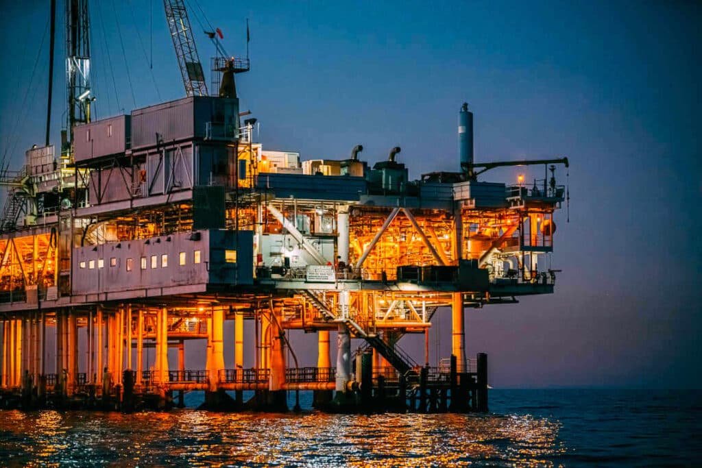
Oil rigs operate in the perfect storm of environmental extremes – where a single cable failure can mean the difference between safe operation and catastrophic disaster.
Cable glands on oil rigs must simultaneously prevent explosive gas ignition, resist saltwater corrosion, maintain electrical integrity in extreme weather, and ensure rapid emergency system response when lives depend on it.
The Unique Hazard Profile
Working with offshore clients for over a decade, I’ve learned that oil rig cable management faces challenges no other industry experiences:
Environmental Extremes:
- Salt spray corrosion 24/7/365
- Temperature swings from -40°C to +80°C
- Hurricane-force winds and wave impacts
- UV radiation at sea level intensity
Safety-Critical Requirements:
- Explosive atmosphere protection (Zone 0, 1, 2)
- Emergency shutdown system reliability
- Fire and gas detection system integrity
- Personnel safety system functionality
Operational Demands:
- Zero-maintenance accessibility during storms
- 20+ year service life expectations
- Rapid replacement during maintenance windows
- Complete traceability for safety audits
Failure Consequences Matrix
| Failure Type | Immediate Risk | Financial Impact | Recovery Time |
|---|---|---|---|
| Explosion-proof breach | Personnel injury/death | $50M+ liability | Indefinite shutdown |
| Corrosion failure | Equipment damage | $2M/day lost production | 3-7 days |
| Seal degradation | System malfunction | $500K/day reduced output | 1-2 days |
| Mechanical failure | Maintenance emergency | $100K+ helicopter costs | 4-12 hours |
Hassan’s experience perfectly illustrates these stakes. His platform’s fire detection system lost three cable connections during a North Sea storm. While backup systems prevented disaster, the incident triggered a full safety audit and $5 million in emergency repairs.
Which Certifications and Materials Can Survive Marine Environments?
Not all “marine-grade” materials are created equal – oil rig environments demand the absolute highest standards of corrosion resistance and safety certification.
Oil rig cable glands require 316L or super duplex stainless steel2 construction, ATEX Zone 0 certification, NORSOK compliance3, and specialized coatings like Inconel or Hastelloy for extreme corrosion resistance.
Material Selection for Extreme Environments
Super Duplex Stainless Steel (2507):
- Superior pitting resistance (PREN >40)
- Excellent stress corrosion cracking resistance
- Maintains strength at temperature extremes
- 25+ year proven offshore track record
316L Stainless Steel with Specialized Coatings:
- Electroless nickel plating for enhanced corrosion protection
- PTFE coating for chemical resistance
- Hard anodizing for wear resistance
- Cost-effective for less critical applications
Exotic Alloys for Extreme Conditions:
- Inconel 625: Ultimate corrosion resistance for H2S environments
- Hastelloy C-276: Superior performance in acidic conditions
- Monel 400: Excellent seawater corrosion resistance
- Titanium Grade 2: Lightweight with exceptional corrosion resistance
Essential Certification Requirements
When David, a procurement manager for a major offshore operator, contacted us last year, he needed glands that met multiple international standards:
Explosion Protection Standards:
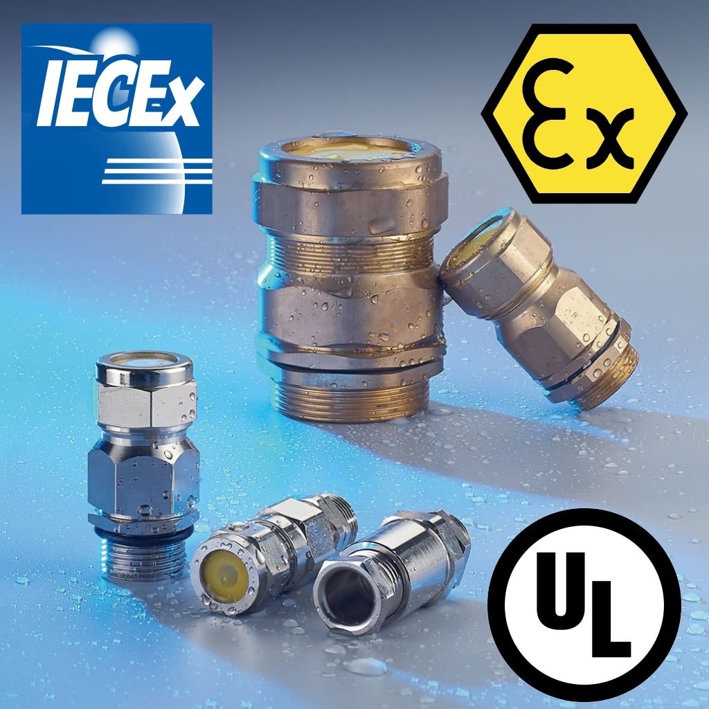
✅ ATEX Directive 2014/34/EU – European explosion protection
✅ IECEx Scheme – International electrotechnical certification
✅ UL 913 – North American hazardous location approval
✅ CSA C22.2 – Canadian safety standards
Marine Environment Standards:
✅ NORSOK M-001 – Norwegian offshore material requirements
✅ DNV GL Type Approval – Maritime classification society certification
✅ API 14F – American Petroleum Institute offshore safety
✅ ISO 13628 – Subsea production system requirements
Quality and Traceability:
✅ NACE MR0175 – Materials for sour service environments
✅ ASTM A262 – Intergranular corrosion testing
✅ EN 10204 3.1 – Material test certificates
✅ FMEA Documentation – Failure mode analysis reports
We provided David with complete certification packages, including material mill certificates with full chemical analysis and mechanical property verification. This documentation was crucial for his company’s safety management system approval.
How Do You Select Explosion-Proof Cable Glands for Different Hazardous Zones?
Understanding hazardous area classifications is critical – the wrong gland selection can literally be explosive, while over-specification wastes millions in unnecessary costs.
Zone 0 areas require Ex ia intrinsically safe4 glands, Zone 1 needs Ex d flameproof or Ex e increased safety designs, and Zone 2 can use Ex nA non-sparking glands with appropriate temperature ratings.
Hazardous Area Classification Guide
Zone 0 (Continuous Gas Presence)
Typical Locations: Inside storage tanks, vapor recovery systems
Required Protection: Ex ia (Intrinsically Safe)
Gland Requirements:
- Certified intrinsically safe barriers
- Blue cable identification required
- Special installation procedures mandatory
- Regular calibration verification needed
Zone 1 (Intermittent Gas Presence)
Typical Locations: Pump areas, compressor stations, loading platforms
Required Protection: Ex d (Flameproof) or Ex e (Increased Safety)
Gland Requirements:
- Flameproof joints with certified gap dimensions
- IP66/67 minimum ingress protection
- Temperature class T4 or better
- Thread engagement length verification
Zone 2 (Abnormal Gas Presence)
Typical Locations: Control rooms, workshop areas, general platform areas
Required Protection: Ex nA (Non-sparking) or general purpose with restrictions
Gland Requirements:
- Standard industrial construction acceptable
- IP65 minimum protection
- Temperature monitoring recommended
- Standard installation practices
Cable Gland Selection Matrix
| Application | Zone | Gland Type | Material | Special Features |
|---|---|---|---|---|
| Gas detection | 0 | Ex ia barrier | 316L SS | Intrinsic safety certification |
| Motor feeds | 1 | Ex d flameproof | Super duplex | Increased safety terminals |
| Instrumentation | 1 | Ex e increased safety | 316L SS | Compound sealing |
| General power | 2 | Ex nA non-sparking | 316L SS | Standard sealing |
| Emergency systems | 1 | Ex d + redundancy | Super duplex | Dual seal design |
Temperature Classification Considerations
Oil rig environments present unique temperature challenges that affect explosion-proof ratings:
T1 (450°C): General electrical equipment
T2 (300°C): Standard motor applications
T3 (200°C): Most instrumentation circuits
T4 (135°C): Required for most hydrocarbon environments
T5 (100°C): Special applications with light hydrocarbons
T6 (85°C): Extremely sensitive gas environments
Hassan’s platform required T4 rating for most applications, but their hydrogen sulfide monitoring systems needed T6 certification. We provided specialized glands with temperature monitoring capabilities to ensure continuous compliance.
What Installation and Maintenance Practices Ensure Long-Term Reliability?
Perfect products fail without proper installation – offshore environments are unforgiving of shortcuts and mistakes that might be acceptable onshore.
Offshore cable gland installation requires certified technicians, specialized tools, comprehensive testing protocols, and detailed documentation for safety audits and insurance compliance.
Pre-Installation Requirements
Personnel Certification:
- ATEX installation competency certification
- Offshore survival training (BOSIET/FOET)
- Electrical safety qualification
- Platform-specific safety induction
Environmental Preparation:
- Weather window planning (wind <25 knots)
- Scaffold/platform safety verification
- Hot work permit5 acquisition
- Gas detection system verification
Tool and Material Verification:
- Calibrated torque wrenches with certificates
- Explosion-proof installation tools
- Thread compound compatibility verification
- Cable preparation tools and materials
Installation Protocol
Step 1: Safety Verification
- Gas detection system operational
- Hot work permit valid
- Emergency response team notified
- Weather conditions acceptable
- Backup power systems verified
Step 2: Mechanical Installation
- Thread engagement verification (minimum 5 full threads)
- Torque application per manufacturer specification
- Thread compound application (approved types only)
- Cable preparation with proper strain relief
- Seal integrity verification
Step 3: Electrical Verification
- Insulation resistance testing (minimum 500V megger)
- Continuity verification for all conductors
- Earth/ground resistance measurement
- Circuit functionality testing
- Emergency shutdown system integration test
Step 4: Documentation and Certification
- Installation certificate completion
- Photographic evidence of installation
- Test result recording and filing
- Safety management system update
- Maintenance schedule establishment
Preventive Maintenance Program
Monthly Inspections:
- Visual corrosion assessment
- Seal integrity verification
- Mechanical tightness check
- Cable strain relief inspection
Quarterly Testing:
- Insulation resistance measurement
- Earth fault loop impedance testing
- Emergency system functionality verification
- Corrosion protection system check
Annual Certification:
- Complete electrical testing protocol
- Explosion-proof joint inspection
- Material condition assessment
- Certification renewal documentation
David’s company implemented our recommended maintenance program after experiencing multiple failures with their previous supplier’s products. The program reduced their cable-related downtime by 75% and provided the documentation needed for insurance premium reductions.
Common Installation Failures to Avoid
From my offshore experience, these mistakes cause 90% of premature failures:
❌ Inadequate thread engagement: Causes mechanical failure in high-vibration environments
❌ Wrong thread compound: Some compounds degrade seals or aren’t explosion-proof rated
❌ Over-tightening: Damages threads and seals, creating leak paths
❌ Poor cable preparation: Allows moisture ingress and conductor corrosion
❌ Incomplete testing: Fails to identify installation defects before commissioning
❌ Missing documentation: Creates compliance issues and maintenance problems
Conclusion
Solving oil rig cable management challenges requires understanding that failure isn’t just expensive – it can be deadly, making proper specification, installation, and maintenance absolutely critical.
FAQs About Oil Rig Cable Management
Q: What’s the difference between ATEX and IECEx certification for offshore applications?
A: ATEX is the European standard required for EU waters, while IECEx provides international recognition. Most offshore operators require both certifications to ensure global compliance and equipment interchangeability between platforms.
Q: How long should cable glands last in offshore marine environments?
A: High-quality stainless steel glands should provide 15-20 years of service with proper maintenance. Super duplex materials can extend this to 25+ years, while standard materials typically fail within 5-7 years in harsh offshore conditions.
Q: Can you retrofit explosion-proof glands without platform shutdown?
A: Limited retrofitting is possible during normal operations using hot work permits and gas monitoring, but major upgrades typically require planned maintenance shutdowns for safety reasons and to ensure proper testing and certification.
Q: What documentation is required for offshore cable gland installations?
A: Complete installation certificates, material traceability documents, test certificates, ATEX/IECEx compliance documentation, maintenance records, and safety management system integration records are typically required for regulatory compliance.
Q: How do you prevent galvanic corrosion between different metals in offshore cable glands?
A: Use compatible materials throughout the installation, apply appropriate thread compounds, ensure proper electrical bonding, and consider sacrificial anode systems for long-term protection in highly corrosive environments.
-
Access the official European Commission page for the ATEX Directive on equipment for potentially explosive atmospheres. ↩
-
Explore the mechanical properties, chemical composition, and superior corrosion resistance of super duplex stainless steel. ↩
-
Learn about the NORSOK standards developed by the Norwegian petroleum industry to ensure safety and cost-effectiveness for offshore operations. ↩
-
Understand the principles of Intrinsic Safety (IS), a protection technique for safe operation of electrical equipment in the most hazardous areas. ↩
-
Review the requirements for a hot work permit and the associated safety procedures for welding, cutting, and other spark-producing operations. ↩


