Introduction
Staring at a flooded control panel after what you thought was a perfect cable gland installation? You’re not alone in this nightmare scenario. One improperly installed IP68 waterproof cable gland1 can cost thousands in equipment damage, downtime, and safety hazards. The frustration of discovering water ingress weeks after installation is something every engineer dreads.
Achieving reliable IP68 waterproof cable gland installation requires precise preparation, proper sealing technique, and systematic torque application – following a methodical 8-step process ensures consistent results and prevents costly water ingress failures that can destroy sensitive electrical equipment.
Just last month, David, a maintenance supervisor at a wastewater treatment facility in Michigan, called us in panic after discovering water inside their main control enclosure. Despite using “waterproof” cable glands, improper installation had compromised the IP68 rating during heavy rainfall. Let me walk you through the exact step-by-step process that prevents these costly mistakes and ensures bulletproof waterproof performance every time.
Table of Contents
- What Tools and Materials Do You Need for IP68 Installation?
- How Do You Properly Prepare the Cable and Enclosure?
- What Is the Correct Assembly Sequence for Maximum Sealing?
- How Do You Apply Proper Torque for IP68 Performance?
- What Testing Methods Verify Your IP68 Installation?
- FAQs About Waterproof Cable Gland Installation
What Tools and Materials Do You Need for IP68 Installation?
Attempting IP68 installation without proper tools is like performing surgery with kitchen utensils – technically possible but guaranteed to fail when it matters most.
Successful IP68 waterproof cable gland installation requires specific tools including calibrated torque wrenches, cable stripping tools, thread sealant, and proper PPE, while material selection must include compatible O-rings, appropriate thread compounds, and correctly sized cable glands for your specific application.
Essential Tool Checklist
Precision Installation Tools:
- Calibrated torque wrench2 (2-50 Nm range minimum)
- Cable stripping tools for clean armor/sheath removal
- Thread cutting oil for smooth installation
- Digital calipers for precise cable diameter measurement
- Deburring tools for smooth cable preparation
Quality Control Equipment:
- Pressure test kit for IP rating verification
- Multimeter for continuity testing
- Flashlight/inspection light for visual verification
- Thread gauges for compatibility checking
Critical Material Selection
Hassan, who manages a petrochemical facility in Saudi Arabia, learned this lesson the hard way. His initial installation used generic O-rings that failed within months due to chemical incompatibility. Here’s what we recommended:
Sealing Materials:
- EPDM O-rings for general outdoor applications
- Viton/FKM seals3 for chemical resistance
- Silicone gaskets for extreme temperature ranges
- PTFE thread sealant for metal-to-metal threads
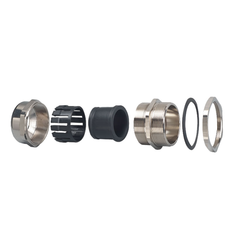
Cable Gland Components:
- 316L stainless steel body for corrosion resistance
- Brass compression nuts with proper plating
- Neoprene cable seals sized for specific cable diameter
- Strain relief components for mechanical protection
Material Compatibility Matrix
| Environment | Body Material | Seal Material | Thread Sealant | Expected Life |
|---|---|---|---|---|
| Marine/Coastal | 316L SS | EPDM/Viton | Marine Grade PTFE | 15+ years |
| Chemical Processing | 316L SS | Viton/FFKM | Chemical Resistant | 10+ years |
| General Industrial | Brass/SS | EPDM | Standard PTFE | 10+ years |
| Food Processing | 316L SS | FDA Silicone | Food Grade | 8+ years |
At Bepto, we provide complete installation kits with pre-selected compatible materials, eliminating guesswork and ensuring optimal performance for your specific application.
Pre-Installation Inspection
Critical Verification Steps:
- Thread compatibility check – verify male/female thread match
- O-ring condition – inspect for nicks, cuts, or contamination
- Cable diameter measurement – ensure proper fit within gland range
- Surface preparation – clean all mating surfaces thoroughly
- Component count – verify all parts present before starting
Remember, discovering missing or incompatible components mid-installation often leads to shortcuts that compromise IP68 performance.
How Do You Properly Prepare the Cable and Enclosure?
Poor preparation is the silent killer of IP68 installations – even premium cable glands fail when basic preparation steps are skipped or rushed.
Proper cable and enclosure preparation involves precise cable stripping to manufacturer specifications, thorough cleaning of all surfaces, deburring sharp edges, and ensuring thread engagement meets minimum requirements for reliable sealing and long-term performance.
Cable Preparation Sequence
Step 1: Accurate Measurement
- Measure cable outer diameter at multiple points
- Account for cable ovality4 (non-round cables)
- Verify cable falls within gland’s specified range
- Document measurements for quality records
Step 2: Precision Stripping
- Strip outer sheath to exact manufacturer specifications
- Critical dimension: Typically 15-20mm for most applications
- Use proper cable stripping tools – avoid knives that can nick conductors
- Ensure clean, square cuts without ragged edges
Step 3: Armor/Shield Preparation
- Fold back braided shields evenly around cable circumference
- Trim armor wires to prevent short circuits
- Apply armor clamps if specified by manufacturer
- Verify no loose strands that could compromise sealing
David’s Michigan facility highlighted a common preparation mistake. Their maintenance team was using utility knives for cable stripping, creating microscopic nicks that allowed water penetration under pressure. After switching to proper stripping tools and following our preparation guidelines, they achieved consistent IP68 performance.
Enclosure Preparation Requirements
Thread Inspection and Cleaning:
- Remove all debris, old sealant, and corrosion from threads
- Use wire brushes and appropriate solvents
- Inspect for damaged threads that could prevent proper sealing
- Apply light coating of thread cutting oil for smooth installation
Surface Preparation:
- Clean all gasket seating surfaces with lint-free cloths
- Remove paint, coating, or oxidation from sealing areas
- Ensure flat, smooth surfaces for proper O-ring compression
- Check for scratches or gouges that could cause leaks
Common Preparation Mistakes to Avoid
Cable Preparation Errors:
- Excessive stripping – exposes too much conductor, creates leak paths
- Insufficient stripping – prevents proper seal compression
- Rough cuts – create stress concentrations and potential failure points
- Contaminated surfaces – oil, grease, or dirt prevents proper sealing
Enclosure Issues:
- Painted threads – prevents proper metal-to-metal contact
- Debris in threads – causes cross-threading and damage
- Damaged gasket surfaces – allows water infiltration
- Incorrect hole size – too large prevents proper compression
Quality Control Checkpoints
Before proceeding to assembly, verify:
- Cable diameter matches gland specifications
- Strip lengths meet manufacturer requirements
- All surfaces are clean and debris-free
- Threads are undamaged and properly prepared
- All components are present and compatible
Hassan’s team now uses a formal checklist system that reduced their installation defects by 90% and eliminated water ingress failures completely.
What Is the Correct Assembly Sequence for Maximum Sealing?
Getting the assembly sequence wrong is like putting on your socks after your shoes – technically you can make it work, but it’s never going to perform properly when tested.
The correct assembly sequence for IP68 performance follows a specific order: thread engagement verification, O-ring positioning, cable insertion with proper seal compression, and systematic tightening to specified torque values while maintaining proper cable positioning throughout the process.

The 8-Step Assembly Process
Step 1: Thread Engagement Check
- Hand-thread the gland into enclosure minimum 5 full turns
- Verify smooth threading without binding or cross-threading
- Apply thin coat of thread sealant to male threads only
- Ensure gland sits flush against enclosure surface
Step 2: O-Ring Installation
- Inspect O-ring for damage, contamination, or incorrect size
- Lubricate O-ring with compatible lubricant (not petroleum-based)
- Install O-ring in proper groove without twisting or stretching
- Verify O-ring seats completely in designated groove
Step 3: Cable Insertion and Positioning
- Insert cable through compression nut and sealing elements
- Position cable to achieve specified strip length
- Ensure cable sits concentrically within gland body
- Verify no conductor strands extend beyond specified limits
Step 4: Seal Element Positioning
- Position primary seal around cable at correct location
- Ensure seal element is not twisted or deformed
- Verify seal diameter matches cable outer diameter
- Check that seal sits squarely against compression surfaces
Step 5: Initial Compression
- Hand-tighten compression nut until seal contact is achieved
- Verify cable cannot be pulled or pushed through seal
- Check that cable remains centered in gland body
- Ensure no binding or misalignment of components
Advanced Assembly Techniques
Compression Monitoring:
Hassan’s petrochemical facility uses a systematic approach that I highly recommend:
Visual Compression Indicators:
- Monitor O-ring deformation during tightening
- Watch for even compression around entire circumference
- Stop immediately if O-ring begins to extrude from groove
- Verify seal material flows evenly around cable
Cable Strain Relief:
- Maintain proper cable bend radius during installation
- Secure cable to prevent tension on gland connection
- Use appropriate cable supports within 12 inches of gland
- Verify no stress concentration at cable entry point
Assembly Quality Verification
Mid-Assembly Checkpoints:
- Thread engagement – minimum 5 full threads engaged
- O-ring position – properly seated without damage
- Cable centering – concentric positioning maintained
- Seal contact – even compression around cable circumference
- Component alignment – no binding or misalignment
Common Assembly Errors:
- Cross-threading – damages threads and prevents proper sealing
- Over-compression – damages seals and reduces effectiveness
- Cable misalignment – creates uneven stress and potential leak paths
- Contaminated seals – dirt or debris prevents proper sealing
- Incorrect sequence – attempting to install components out of order
David’s team discovered that rushing the assembly process was their primary cause of failures. After implementing our systematic 8-step process with mandatory checkpoints, their installation success rate improved from 75% to 99%.
Final Assembly Verification
Before applying final torque:
- All components properly positioned
- Cable centered and strain-relieved
- O-rings undamaged and properly seated
- No cross-threading or binding
- Compression nut hand-tight with good contact
This systematic approach ensures every installation meets IP68 requirements consistently, regardless of technician experience level.
How Do You Apply Proper Torque for IP68 Performance?
Torque application separates professional installations from amateur attempts – too little and you’ll have leaks, too much and you’ll damage critical sealing components.
Proper torque application for IP68 performance requires calibrated tools, manufacturer-specified values, and systematic tightening patterns that ensure even seal compression without over-stressing components, typically ranging from 15-45 Nm depending on gland size and material construction.
Torque Specification Guidelines
Standard Torque Values by Size:
| Gland Size | Material | Torque Range (Nm) | Wrench Size | Typical Application |
|---|---|---|---|---|
| M12x1.5 | Brass/SS | 8-12 | 19mm | Small control cables |
| M16x1.5 | Brass/SS | 12-18 | 22mm | Instrumentation |
| M20x1.5 | Brass/SS | 15-25 | 27mm | Power/control cables |
| M25x1.5 | Brass/SS | 20-30 | 32mm | Medium power cables |
| M32x1.5 | Brass/SS | 25-40 | 41mm | Large power cables |
| M40x1.5 | Brass/SS | 35-50 | 50mm | Heavy-duty applications |
Important Note: Always consult manufacturer specifications as values can vary based on seal design and material combinations.
Systematic Torque Application Process
Phase 1: Initial Tightening (25% of Final Torque)
- Apply initial torque to seat all components
- Verify even compression around entire circumference
- Check for any binding or misalignment
- Ensure cable remains properly positioned
Phase 2: Progressive Tightening (50% of Final Torque)
- Increase torque gradually in 25% increments
- Monitor seal compression and O-ring deformation
- Stop if excessive resistance is encountered
- Verify no component damage or extrusion
Phase 3: Final Torque Application (100% of Specification)
- Apply final torque value using calibrated wrench
- Hold torque for 5-10 seconds to allow seal settling
- Verify torque retention after 30 seconds
- Document final torque value for records
Hassan’s facility implemented a color-coded torque verification system that I recommend for critical applications:
Torque Verification System:
- Green tag: Properly torqued within specification
- Yellow tag: Requires re-torque verification
- Red tag: Over-torqued or damaged, requires replacement
Environmental Torque Adjustments
Temperature Compensation:
- Hot installations (>40°C): Reduce torque by 10-15%
- Cold installations (<0°C): Increase torque by 5-10%
- Thermal cycling environments: Use mid-range torque values
Material-Specific Considerations:
- Stainless steel: Higher torque resistance, use upper range
- Brass/Bronze: More prone to galling5, use thread lubricant
- Aluminum: Lower strength, avoid over-torquing
Torque Tool Calibration and Maintenance
David’s Michigan facility learned the importance of tool calibration after several failures traced to an uncalibrated torque wrench reading 20% high. Their new protocol includes:
Calibration Schedule:
- Monthly verification for frequently used tools
- Annual professional calibration for all torque tools
- Immediate calibration after any drops or impacts
- Documentation of all calibration activities
Tool Selection Criteria:
- Accuracy: ±3% of reading minimum
- Range: Covers your application requirements with 20-80% usage
- Type: Click-type preferred for consistent results
- Certification: Traceable calibration certificates required
Post-Torque Verification
Immediate Checks:
- Torque retention after 60 seconds
- No visible seal extrusion or damage
- Cable remains properly positioned
- No binding or component misalignment
- Gland body flush against enclosure
24-Hour Follow-up:
- Re-check torque values (seal settling may occur)
- Visual inspection for any changes
- Verify no loosening has occurred
- Document any adjustments made
This systematic approach to torque application ensures consistent IP68 performance and eliminates the guesswork that leads to installation failures.
What Testing Methods Verify Your IP68 Installation?
Testing is where confidence meets reality – you can follow every installation step perfectly, but without proper verification, you’re gambling with equipment protection and safety.
Effective IP68 verification combines visual inspection, pressure testing, and electrical continuity checks using standardized test procedures that simulate real-world conditions, ensuring your installation will maintain waterproof integrity throughout its service life under specified operating conditions.
Comprehensive Testing Protocol
Level 1: Visual Inspection (Immediate)
- Seal compression verification: Even deformation around entire circumference
- O-ring position check: No extrusion or displacement from grooves
- Thread engagement: Minimum 5 full threads with proper seating
- Cable positioning: Centered with proper strain relief
- Component alignment: No binding, cross-threading, or damage
Level 2: Low-Pressure Testing (30 minutes post-installation)
- Test pressure: 0.5 bar (7.25 PSI) for 15 minutes minimum
- Bubble testing: Submerge connection in soapy water solution
- Pressure retention: No pressure drop over test period
- Visual monitoring: No bubble formation at any interface
Level 3: Full IP68 Pressure Testing (24 hours post-installation)
- Test pressure: 1.5 bar (21.75 PSI) continuous for 30 minutes
- Submersion depth: 1.5 meters minimum as per IP68 standard
- Duration: Continuous pressure for specified test period
- Pass criteria: Zero pressure loss and no water ingress
Real-World Testing Examples
Hassan’s petrochemical facility uses a three-stage testing protocol that has eliminated all water ingress failures:
Stage 1: Installation Quality Check
- Immediate visual inspection using standardized checklist
- Torque verification with calibrated equipment
- Cable pull test to verify strain relief adequacy
- Photographic documentation for quality records
Stage 2: Operational Pressure Test
- Pressurize to 1.2x maximum operating pressure
- Monitor for 60 minutes with continuous pressure logging
- Accept zero pressure loss as pass criteria
- Document test results in installation records
Stage 3: Environmental Simulation
- Temperature cycling from -20°C to +60°C
- Vibration testing per application requirements
- Chemical compatibility verification if applicable
- Long-term monitoring for first 30 days of operation
Testing Equipment and Procedures
Pressure Testing Setup:
- Pressure source: Regulated air supply or hand pump
- Pressure gauge: Calibrated to ±1% accuracy minimum
- Test chamber: Transparent container for visual monitoring
- Safety equipment: Pressure relief valves and protective barriers
Electrical Continuity Testing:
- Insulation resistance: Minimum 10 MΩ at 500V DC
- Conductor continuity: Less than 0.1Ω resistance increase
- Ground continuity: Verify armor/shield connections
- Dielectric strength: Per cable manufacturer specifications
Common Testing Failures and Solutions
David’s Michigan facility identified several common failure modes through systematic testing:
Failure Mode 1: Slow Pressure Loss
- Cause: Incomplete O-ring seating or contamination
- Solution: Disassemble, clean, and reinstall with proper technique
- Prevention: Enhanced surface preparation and inspection
Failure Mode 2: Immediate Pressure Loss
- Cause: Cross-threading or damaged components
- Solution: Replace damaged parts and reinstall correctly
- Prevention: Careful thread engagement and torque control
Failure Mode 3: Intermittent Failures
- Cause: Inadequate strain relief or thermal cycling stress
- Solution: Improve cable support and use flexible connections
- Prevention: Proper mechanical design and installation planning
Documentation and Record Keeping
Required Documentation:
- Installation checklist with technician signature
- Torque values and calibration certificates
- Pressure test results with time/date stamps
- Photographic evidence of proper installation
- Material certificates and compatibility verification
Long-term Monitoring:
- Monthly visual inspections for first year
- Annual pressure testing for critical applications
- Immediate testing after any maintenance or disturbance
- Trend analysis of test results over time
This comprehensive testing approach provides confidence that your IP68 installation will perform reliably throughout its intended service life, protecting valuable equipment and ensuring operational safety.
Conclusion
Achieving perfect IP68 waterproof cable gland installation isn’t about luck or experience alone – it’s about following a systematic, proven process that eliminates variables and ensures consistent results. From proper tool selection and material compatibility through precise assembly sequences and comprehensive testing, every step builds upon the previous to create bulletproof waterproof protection. Remember David’s lesson about preparation importance and Hassan’s systematic approach to quality control – these real-world examples demonstrate that investing time in proper installation procedures prevents costly equipment failures and safety incidents. At Bepto, we provide not just premium waterproof cable glands but complete installation support including detailed procedures, compatible materials, and technical expertise to ensure your IP68 installations perform flawlessly for years to come. The difference between a good installation and a perfect one lies in the details – and those details can save thousands in prevented failures.
FAQs About Waterproof Cable Gland Installation
Q: How long should I wait before testing my IP68 cable gland installation?
A: Wait minimum 30 minutes after final torque application before pressure testing to allow seals to settle properly. For critical applications, perform initial testing after 30 minutes, then retest after 24 hours to verify long-term seal integrity and catch any delayed failures.
Q: What torque wrench accuracy do I need for reliable IP68 installation?
A: Use a calibrated torque wrench with minimum ±3% accuracy that covers your application range within 20-80% of the tool’s capacity. Monthly calibration verification is recommended for frequently used tools, with annual professional calibration required for consistent results.
Q: Can I reuse cable glands if I need to remove them for maintenance?
A: Generally no – O-rings and sealing elements should be replaced whenever a cable gland is disassembled. The compression and deformation during initial installation compromises their sealing ability, making reuse unreliable for maintaining IP68 performance in critical applications.
Q: What’s the most common cause of IP68 installation failures?
A: Inadequate surface preparation accounts for approximately 60% of failures, including contaminated threads, damaged O-ring grooves, and improper cable stripping. Following systematic preparation procedures and using proper tools eliminates most installation failures.
Q: How do I know if my cable diameter is compatible with the gland size?
A: Measure cable outer diameter at multiple points and ensure it falls within the gland’s specified range with proper tolerance. The cable should fit snugly but not require excessive force – typically allowing 0.5-1.0mm clearance for optimal seal compression and performance.
-
Understand the official definition of the IP68 rating according to the international standard IEC 60529. ↩
-
Learn why using a calibrated torque wrench is critical for achieving precise and reliable mechanical assemblies. ↩
-
Explore the chemical resistance and material properties of Viton™ (FKM) fluoroelastomers. ↩
-
Discover what cable ovality is and how it can impact the effectiveness of a waterproof seal. ↩
-
Understand the phenomenon of thread galling (cold welding) and how to prevent it in threaded fasteners. ↩