Signal interference and electromagnetic compatibility1 issues plague modern electronic systems, causing costly malfunctions, data corruption, and regulatory compliance failures that could be prevented with proper EMC cable gland selection. Engineers struggle to maintain signal integrity in increasingly complex electromagnetic environments, unsure how cable entry points affect overall system performance. Poor EMC design at cable glands creates weak points that compromise entire system reliability and performance.
EMC cable glands maintain signal integrity through 360-degree electromagnetic shielding, controlled impedance pathways, and proper grounding techniques that prevent electromagnetic interference from entering or exiting electronic enclosures. Understanding EMC principles and proper implementation ensures optimal signal quality and regulatory compliance in high-frequency applications.
After analyzing EMC performance data from thousands of installations across telecommunications, automotive, and industrial automation sectors, I’ve identified the critical factors that separate effective EMC cable glands from standard cable entry solutions. Let me share the technical insights that will help you achieve peak signal integrity performance in your most demanding applications.
Table of Contents
- What Makes EMC Cable Glands Essential for Signal Integrity?
- How Do EMC Glands Provide 360-Degree Electromagnetic Shielding?
- Which Design Features Optimize High-Frequency Performance?
- What Are the Key Installation Requirements for Maximum EMC Effectiveness?
- FAQs About EMC Cable Glands and Signal Integrity
What Makes EMC Cable Glands Essential for Signal Integrity?
EMC cable glands serve as critical components in maintaining electromagnetic compatibility by controlling how electromagnetic energy interacts with cable entry points in electronic enclosures.
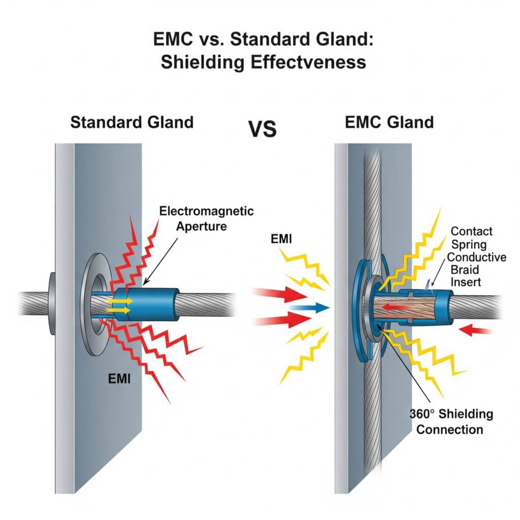
EMC cable glands are essential because standard cable glands create electromagnetic apertures that allow interference to penetrate enclosures, while EMC variants provide continuous shielding that maintains the Faraday cage2 integrity required for signal integrity and regulatory compliance. This shielding continuity prevents both ingress and egress of electromagnetic interference.
The Electromagnetic Compatibility Challenge
Modern electronic systems face increasingly complex EMC challenges:
Interference Sources:
- Switching power supplies: High-frequency harmonics and transients
- Digital circuits: Clock frequencies and data transitions
- Wireless communications: RF transmissions and cellular signals
- Industrial equipment: Motor drives, welding equipment, high-power switching
- Environmental EMI: Lightning, electrostatic discharge, radio broadcasts
Signal Integrity Threats:
- Conducted interference: Currents flowing on cable shields and conductors
- Radiated interference: Electromagnetic fields coupling into cables
- Ground loops: Potential differences causing circulating currents
- Common-mode noise3: Interference affecting multiple conductors simultaneously
- Differential-mode noise: Interference between signal conductors
Working with David, a senior engineer at a major telecommunications equipment manufacturer in Germany, we discovered that standard cable glands in their 5G base station enclosures were creating EMC compliance issues. Switching to our EMC cable glands eliminated interference problems and achieved CE marking requirements, preventing costly redesign and regulatory delays.
EMC Gland Operating Principles
EMC cable glands maintain signal integrity through multiple mechanisms:
Electromagnetic Shielding:
- Conductive housing: Low-resistance path for electromagnetic currents
- 360-degree contact: Continuous electrical connection around cable shield
- Frequency response: Effective across wide frequency ranges (DC to GHz)
- Shielding effectiveness: Typically 60-80 dB attenuation
Impedance Control:
- Controlled geometry: Maintains characteristic impedance of cable systems
- Minimized discontinuities: Reduces reflections and signal distortion
- Ground plane continuity: Provides stable reference for signal returns
- Transition management: Smooth impedance transitions at entry points
Performance Metrics and Standards
EMC cable glands are evaluated using standardized test methods:
| Parameter | Test Standard | Typical Performance | Application Impact |
|---|---|---|---|
| Shielding Effectiveness | IEC 62153-4-3 | 60-80 dB | EMI suppression capability |
| Transfer Impedance4 | IEC 62153-4-3 | <1 mΩ/m | High-frequency performance |
| Coupling Attenuation | IEC 62153-4-4 | >60 dB | Crosstalk prevention |
| DC Resistance | IEC 60512 | <5 mΩ | Grounding effectiveness |
| Frequency Range | Various | DC-6 GHz | Application bandwidth |
Application-Specific Requirements
Different applications demand specific EMC performance characteristics:
Telecommunications Equipment:
- Frequency range: DC to 6 GHz and beyond
- Shielding effectiveness: >70 dB required
- Standards compliance: FCC Part 15, ETSI EN 301 489
- Critical factors: High-frequency performance, temperature stability
Automotive Electronics:
- Frequency range: 150 kHz to 1 GHz primary concern
- Shielding effectiveness: >60 dB typical requirement
- Standards compliance: CISPR 255, ISO 11452
- Critical factors: Vibration resistance, temperature cycling
Industrial Automation:
- Frequency range: DC to 400 MHz typical
- Shielding effectiveness: >50 dB adequate for most applications
- Standards compliance: IEC 61000 series
- Critical factors: Mechanical robustness, chemical resistance
How Do EMC Glands Provide 360-Degree Electromagnetic Shielding?
The key to EMC cable gland effectiveness lies in achieving complete, continuous electromagnetic shielding around the cable entry point without compromising mechanical sealing performance.
EMC cable glands achieve 360-degree shielding through specialized conductive contact systems that create continuous electrical connection between cable shields and enclosure walls, while maintaining environmental sealing through dual-barrier designs. This comprehensive approach ensures both electromagnetic and environmental protection.
Shielding Contact Technologies
Different EMC cable glands employ various contact mechanisms:
Spring Contact Systems:
- Design: Multiple spring fingers provide radial contact pressure
- Advantages: Accommodates cable diameter variations, maintains contact under vibration
- Performance: Excellent high-frequency characteristics, low contact resistance
- Applications: Telecommunications, aerospace, high-reliability systems
Compression Ring Systems:
- Design: Conductive compression ring deforms to create 360-degree contact
- Advantages: Simple installation, cost-effective, reliable contact
- Performance: Good DC to moderate frequency performance
- Applications: Industrial automation, automotive, general EMC applications
Brush Contact Systems:
- Design: Conductive brush elements create multiple contact points
- Advantages: Excellent contact reliability, accommodates cable movement
- Performance: Superior high-frequency performance, low impedance
- Applications: Military, aerospace, critical communications
Working with Hassan, who manages EMC compliance for a major automotive supplier in Detroit, we addressed shielding effectiveness issues in their electric vehicle control units. Standard compression-type EMC glands weren’t providing adequate high-frequency shielding. Our spring contact EMC glands improved shielding effectiveness from 45 dB to 72 dB, ensuring CISPR 25 compliance across the full frequency range.
Contact Material Selection
The choice of contact materials significantly affects EMC performance:
Beryllium Copper:
- Properties: Excellent conductivity, spring characteristics, corrosion resistance
- Performance: Superior high-frequency response, long-term reliability
- Applications: High-performance telecommunications, aerospace applications
- Considerations: Higher cost, special handling requirements
Phosphor Bronze:
- Properties: Good conductivity, adequate spring properties, cost-effective
- Performance: Suitable for moderate frequency applications
- Applications: Industrial automation, automotive, general EMC needs
- Considerations: Limited high-frequency performance compared to beryllium copper
Silver-Plated Contacts:
- Properties: Excellent conductivity, oxidation resistance
- Performance: Superior electrical characteristics across frequency range
- Applications: Critical EMC applications, high-reliability systems
- Considerations: Higher cost, potential tarnishing in sulfur environments
Shielding Effectiveness Measurement
EMC cable gland performance is quantified through standardized testing:
Test Setup Requirements:
- Frequency range: Typically 30 MHz to 1 GHz minimum
- Test fixtures: Standardized coaxial test cells or triaxial setups
- Measurement equipment: Network analyzers, EMI receivers
- Cable specifications: Defined impedance and shielding characteristics
Performance Categories:
- Class A: >40 dB shielding effectiveness (basic EMC applications)
- Class B: >60 dB shielding effectiveness (standard industrial/automotive)
- Class C: >80 dB shielding effectiveness (telecommunications/aerospace)
- Class D: >100 dB shielding effectiveness (military/critical applications)
Which Design Features Optimize High-Frequency Performance?
High-frequency EMC performance requires careful attention to design details that minimize electromagnetic discontinuities and maintain controlled impedance characteristics.
Optimal high-frequency EMC cable gland design features include minimized internal geometry changes, controlled impedance transitions, high-quality conductive materials, and proper grounding interfaces that maintain signal integrity across wide frequency ranges. These design elements work together to prevent signal degradation and EMI generation.
Impedance Control Design Elements
Geometry Optimization:
- Smooth transitions: Gradual changes in cross-sectional area minimize reflections
- Controlled dimensions: Precise manufacturing maintains characteristic impedance
- Minimal discontinuities: Reduced sharp edges and abrupt changes
- Symmetrical design: Balanced geometry prevents mode conversion
Material Selection Impact:
- Dielectric properties: Low-loss materials minimize signal attenuation
- Conductivity: High-conductivity metals reduce resistive losses
- Permeability: Non-magnetic materials prevent frequency-dependent effects
- Stability: Temperature-stable materials maintain consistent performance
Advanced EMC Gland Features
Modern EMC cable glands incorporate sophisticated design elements:
Multi-Stage Shielding:
- Primary shield contact: Direct connection to cable outer shield
- Secondary shield contact: Additional contact to cable inner shield
- Enclosure bonding: Low-impedance connection to enclosure ground
- Isolation barriers: Prevent ground loops while maintaining shielding
Frequency-Specific Optimizations:
- Resonance suppression: Design features that prevent resonant frequencies
- Broadband performance: Consistent effectiveness across wide frequency ranges
- High-frequency extensions: Special designs for millimeter-wave applications
- Ultra-wideband capability: Performance from DC to multi-GHz frequencies
Performance Comparison Analysis
| Design Feature | Standard EMC Gland | Advanced EMC Gland | Performance Benefit |
|---|---|---|---|
| Contact System | Single compression ring | Multi-point spring contacts | 15-20 dB improvement |
| Frequency Range | DC-400 MHz | DC-6 GHz+ | Extended application range |
| Impedance Control | Basic geometry | Optimized transitions | Reduced signal reflections |
| Material Quality | Standard brass/steel | Premium alloys/plating | Improved long-term stability |
| Installation Tolerance | ±0.5mm typical | ±0.1mm precision | Consistent performance |
Working with Maria, an EMC engineer at a major defense contractor, we developed custom EMC cable glands for radar applications operating up to 18 GHz. Standard EMC glands showed significant performance degradation above 2 GHz. Our advanced design with optimized geometry and premium materials maintained >70 dB shielding effectiveness across the full frequency range.
What Are the Key Installation Requirements for Maximum EMC Effectiveness?
Proper installation is critical for achieving specified EMC performance, as installation errors can completely negate the benefits of high-quality EMC cable glands.
Maximum EMC effectiveness requires proper cable preparation, correct gland sizing, adequate torque application, and verified electrical continuity, with installation quality often determining whether EMC cable glands achieve their specified shielding performance. Following manufacturer installation procedures ensures optimal electromagnetic compatibility.
Cable Preparation Requirements
Shield Preparation:
- Shield exposure: Expose sufficient shield length for complete contact engagement
- Braid management: Properly fold back braided shields without breaking strands
- Foil handling: Carefully manage foil shields to prevent tearing or gaps
- Conductor protection: Prevent shield strands from contacting inner conductors
Dimensional Verification:
- Cable diameter: Verify actual cable diameter matches gland specifications
- Shield coverage: Ensure adequate shield coverage percentage (>85% typical)
- Concentricity: Check cable concentricity to ensure even contact pressure
- Surface condition: Clean cable surface of oils, dirt, or oxidation
Installation Process Optimization
Step-by-Step Installation:
- Pre-installation inspection: Verify gland and cable compatibility
- Cable preparation: Follow manufacturer’s shield preparation guidelines
- Gland assembly: Assemble components in correct sequence
- Installation: Insert cable with proper shield engagement
- Torque application: Apply specified torque values using calibrated tools
- Continuity verification: Test electrical continuity of shield connection
Critical Installation Parameters:
- Torque specifications: Typically 5-15 Nm depending on gland size
- Contact pressure: Sufficient to deform contact elements without damage
- Shield engagement: Minimum 360-degree contact around full circumference
- Environmental sealing: Maintain IP rating while achieving EMC performance
Verification and Testing Procedures
Installation Verification Methods:
- Visual inspection: Check shield engagement and contact alignment
- Continuity testing: Verify low-resistance connection (<5 mΩ typical)
- Insulation testing: Confirm isolation between conductors and shield
- Mechanical testing: Verify proper retention and sealing
Performance Validation:
- Shielding effectiveness: Field testing using portable EMC equipment
- Transfer impedance: Laboratory measurement for critical applications
- Environmental testing: Verify performance after temperature/vibration exposure
- Long-term monitoring: Periodic verification of EMC performance
Common Installation Mistakes and Solutions
| Installation Error | Consequence | Prevention Method |
|---|---|---|
| Insufficient shield exposure | Poor contact, reduced shielding | Follow cable prep specifications |
| Over-tightening | Contact damage, shield breakage | Use calibrated torque tools |
| Contaminated surfaces | High contact resistance | Clean all surfaces before assembly |
| Incorrect gland sizing | Poor fit, inadequate contact | Verify cable diameter accuracy |
| Damaged shield during prep | Reduced shielding effectiveness | Use proper cable preparation tools |
At Bepto Connector, we provide comprehensive installation training and detailed technical documentation to ensure our EMC cable glands achieve their specified performance. Our technical support team assists customers with application-specific installation requirements and troubleshooting to maximize EMC effectiveness in their critical applications.
Conclusion
EMC cable glands play a crucial role in maintaining signal integrity by providing continuous electromagnetic shielding at cable entry points. Success depends on selecting appropriate EMC gland designs for your frequency range and application requirements, followed by proper installation procedures that ensure optimal contact and shielding performance.
The key to peak EMC performance lies in understanding the relationship between gland design features, installation quality, and system-level EMC requirements. At Bepto Connector, our EMC cable glands combine advanced design features with comprehensive technical support to help you achieve superior signal integrity and regulatory compliance in your most demanding electromagnetic environments.
FAQs About EMC Cable Glands and Signal Integrity
Q: What’s the difference between EMC cable glands and standard cable glands?
A: EMC cable glands provide electromagnetic shielding through conductive contact systems that connect cable shields to enclosure grounds, while standard cable glands only provide mechanical retention and environmental sealing. EMC variants prevent electromagnetic interference from entering or leaving electronic enclosures.
Q: How do I choose the right EMC cable gland for high-frequency applications?
A: Select based on your frequency range requirements, with spring contact systems preferred for frequencies above 1 GHz and compression systems adequate for lower frequencies. Verify shielding effectiveness specifications match your EMC requirements and consider impedance control features for signal integrity applications.
Q: Can EMC cable glands maintain both electromagnetic shielding and environmental sealing?
A: Yes, quality EMC cable glands use dual-barrier designs that provide both EMC shielding and IP-rated environmental protection. The electromagnetic contact system operates independently of the environmental sealing elements, allowing both functions to be optimized simultaneously.
Q: What installation mistakes most commonly reduce EMC cable gland effectiveness?
A: The most common mistakes are insufficient cable shield preparation, incorrect torque application, and contaminated contact surfaces. These errors can reduce shielding effectiveness by 20-40 dB. Proper cable preparation and following manufacturer torque specifications are critical for achieving specified performance.
Q: How can I verify that my EMC cable glands are working properly after installation?
A: Test electrical continuity between cable shield and enclosure ground (should be <5 mΩ), perform visual inspection of shield contact engagement, and consider field EMC testing for critical applications. Regular monitoring helps identify performance degradation before it affects system operation.
-
Learn the fundamentals of EMC, the branch of electrical engineering concerned with the unintentional generation, propagation, and reception of electromagnetic energy. ↩
-
Discover the physics behind the Faraday cage, an enclosure used to block electromagnetic fields. ↩
-
Understand the difference between these two types of electrical noise and how they affect signal integrity. ↩
-
Explore this key parameter used to characterize the shielding effectiveness of cables, connectors, and cable glands at high frequencies. ↩
-
Review the scope of this international standard, which specifies limits and methods for measuring radio disturbances from vehicles and devices. ↩
