Lightning strikes cause billions of dollars in damage annually to critical infrastructure, destroying sensitive electronics and creating dangerous electrical hazards when protection systems fail. Standard cable glands become weak points in lightning protection networks, allowing surge currents to bypass grounding systems and damage expensive equipment through inadequate bonding and shielding.
Cable glands in lightning protection systems must provide continuous electrical bonding, electromagnetic shielding, and surge current paths while maintaining weatherproof sealing and mechanical integrity under extreme electrical stress. Specialized lightning protection cable glands incorporate conductive materials, enhanced grounding features, and surge-resistant designs that ensure protection system effectiveness during electrical storms.
Having worked with telecommunications companies, power utilities, and industrial facilities across North America and Europe—from cellular tower installations to petrochemical plants—I’ve seen how proper cable gland selection can mean the difference between system survival and catastrophic failure during lightning events. Let me share the critical knowledge every engineer needs for lightning protection applications.
Table of Contents
- What Makes Lightning Protection Cable Glands Different?
- How Do Cable Glands Affect Lightning Protection System Performance?
- Which Cable Gland Features Are Essential for Lightning Protection?
- What Are the Key Installation Requirements for Lightning Protection?
- How to Select the Right Cable Glands for Different Protection Zones?
- FAQs About Lightning Protection Cable Glands
What Makes Lightning Protection Cable Glands Different?
Lightning protection cable glands require specialized conductive materials, enhanced bonding capabilities, surge current handling capacity, and electromagnetic shielding performance that far exceeds standard industrial cable glands designed for normal electrical applications.
Understanding these specialized requirements is crucial because standard cable glands can actually compromise lightning protection system effectiveness by creating high-resistance paths and electromagnetic vulnerabilities.
Electrical Conductivity Requirements
Low-Resistance Bonding: Lightning protection cable glands must maintain extremely low electrical resistance (typically <10 milliohms) between cable shields and equipment grounding systems to ensure effective surge current dissipation.
Surge Current Capacity: These glands must handle peak surge currents up to 100kA or more without degradation, requiring robust conductive paths and materials that won’t melt or oxidize under extreme electrical stress.
Frequency Response: Lightning surges contain high-frequency components that require cable glands with consistent impedance characteristics across a wide frequency range to prevent reflections and standing waves.
Corrosion Resistance: Long-term electrical performance depends on materials that resist galvanic corrosion1 when different metals are in contact, particularly important in outdoor installations exposed to moisture.
I remember working with Robert, a telecommunications engineer managing a major cellular network expansion across Texas. His initial installations used standard EMC cable glands on tower equipment, thinking they would provide adequate lightning protection. After several lightning-related equipment failures, investigation revealed that the glands weren’t designed for surge current handling. Upgrading to our specialized lightning protection glands with enhanced surge capacity eliminated subsequent failures and saved thousands in equipment replacement costs. 😊
Material Specifications
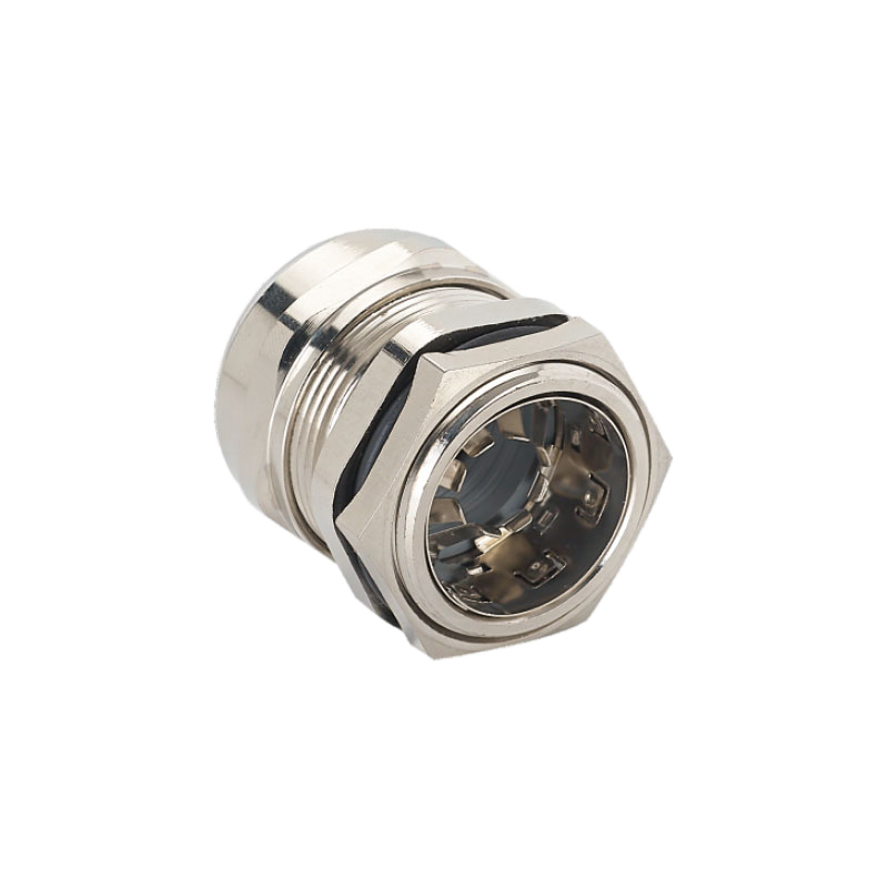
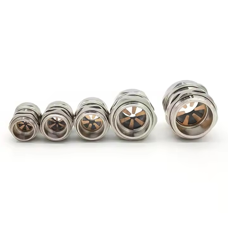
Conductive Body Materials: Brass, bronze, or specialized conductive composites provide the necessary electrical properties while maintaining mechanical strength and environmental resistance.
Enhanced Sealing Systems: Lightning protection environments often involve extreme weather conditions, requiring sealing materials that maintain integrity despite temperature cycling and UV exposure.
EMI Shielding Effectiveness: Specialized cable glands must provide 360-degree electromagnetic shielding with effectiveness ratings of 80dB or higher to prevent interference with sensitive protection equipment.
Grounding Hardware: Integrated grounding lugs, bonding straps, and connection points ensure proper electrical continuity without additional hardware that could create resistance or failure points.
Environmental Durability
Weather Resistance: Outdoor lightning protection installations require cable glands rated for extreme temperature ranges, UV exposure, and severe weather conditions including ice, wind, and precipitation.
Vibration Tolerance: Lightning protection systems on towers, poles, and industrial structures experience significant wind-induced vibration that can loosen connections and degrade electrical performance over time.
Chemical Compatibility: Industrial lightning protection systems may be exposed to corrosive atmospheres, cleaning chemicals, and industrial processes that can attack standard materials.
Salt Spray Resistance: Coastal installations require enhanced corrosion protection against salt spray and marine environments that accelerate degradation of electrical connections.
How Do Cable Glands Affect Lightning Protection System Performance?
Cable glands directly impact lightning protection effectiveness by controlling surge current paths, maintaining electromagnetic shielding continuity, and ensuring proper grounding system integration—making them critical components rather than simple cable entry devices.
Poor cable gland selection or installation can compromise entire lightning protection systems, creating vulnerabilities that allow surge damage to sensitive equipment.
Surge Current Path Management
Primary Protection Zones: Cable glands at the boundary between lightning protection zones must handle full surge currents while maintaining low impedance paths to grounding systems.
Secondary Protection Integration: Glands connecting to surge protection devices must coordinate with protection device characteristics to ensure proper operation during lightning events.
Grounding System Continuity: Cable glands provide critical links in the grounding system chain, and any high-resistance connections can cause dangerous voltage differences during surge events.
Multiple Path Coordination: Complex installations with multiple cable entries require coordinated grounding through all cable glands to prevent circulating currents and ground loops2.
Electromagnetic Shielding Continuity
Shield Termination: Proper cable shield termination through specialized cable glands maintains electromagnetic protection from the cable entry point through the entire system.
Transfer Impedance Control: Lightning protection cable glands must maintain consistent transfer impedance to prevent high-frequency coupling between external fields and internal conductors.
Aperture Sealing: Any gaps or discontinuities in electromagnetic shielding create apertures that allow electromagnetic energy to penetrate protection systems.
Multi-Cable Installations: When multiple cables enter through a single panel, cable glands must maintain shielding effectiveness while accommodating different cable types and sizes.
System Integration Challenges
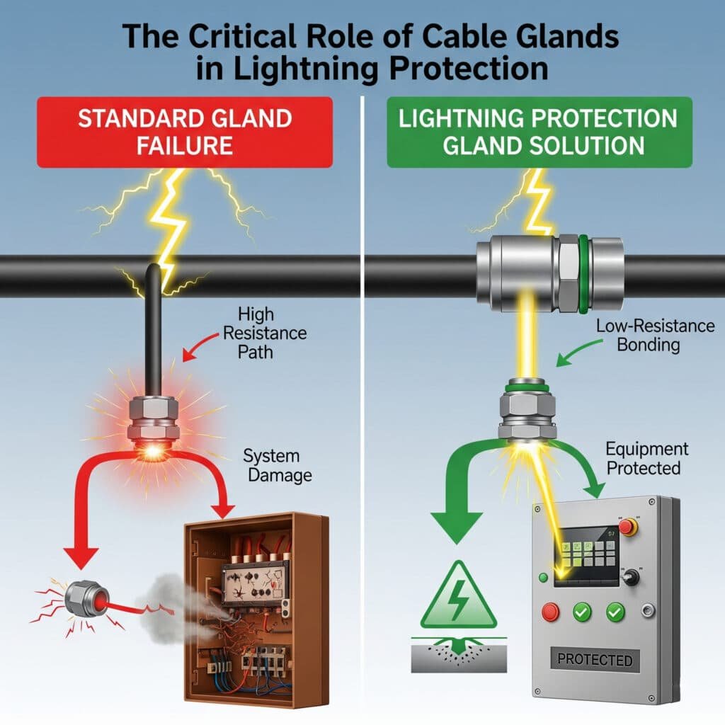
| Challenge | Standard Gland Impact | Lightning Protection Gland Solution |
|---|---|---|
| Surge Current | High resistance path causes voltage rise | Low-resistance bonding handles full surge current |
| EMI Shielding | Poor shield termination allows interference | 360-degree shielding maintains protection |
| Grounding | Inconsistent bonding creates vulnerabilities | Integrated grounding ensures continuity |
| Environmental | Degradation reduces protection over time | Enhanced materials maintain long-term performance |
Coordination with Protection Devices: Cable glands must work in coordination with surge protection devices, ensuring that surge currents flow through intended protection paths rather than bypassing through cable shields.
System Grounding Integration: Lightning protection systems require single-point grounding or carefully controlled multi-point grounding, and cable glands play a crucial role in maintaining proper grounding architecture.
Maintenance Accessibility: Lightning protection systems require regular inspection and testing, so cable gland installations must allow access for maintenance while maintaining protection integrity.
Marcus, who manages lightning protection for a major petrochemical complex in Louisiana, learned about system integration after experiencing repeated failures in their distributed control systems during thunderstorms. Investigation revealed that standard cable glands were creating multiple ground reference points, causing ground loops and surge current circulation. After implementing our integrated lightning protection cable gland system with coordinated grounding, their control system reliability improved dramatically during storm seasons.
Which Cable Gland Features Are Essential for Lightning Protection?
Essential lightning protection cable gland features include low-resistance bonding systems, surge current handling capability, 360-degree EMI shielding, integrated grounding provisions, and environmental sealing that maintains performance under extreme electrical and weather conditions.
These specialized features work together to ensure lightning protection system effectiveness while providing long-term reliability in demanding outdoor environments.
Electrical Performance Features
Bonding Continuity: Specialized bonding systems ensure continuous electrical connection between cable shields, gland bodies, and equipment grounding systems with resistance measurements in milliohms.
Surge Current Rating: Lightning protection glands must be rated for peak surge currents (8/20 μs waveform3) and total charge transfer without degradation or failure.
Impedance Control: Consistent characteristic impedance prevents reflections and standing waves that can cause voltage multiplication and equipment damage.
Frequency Response: Wide bandwidth performance ensures effectiveness against lightning’s broad frequency spectrum from DC to several MHz.

Mechanical Construction
Robust Materials: Heavy-duty construction using materials like marine-grade brass, 316L stainless steel, or specialized conductive composites that maintain properties under electrical stress.
Enhanced Thread Design: Reinforced threads with locking features prevent loosening under vibration while maintaining electrical continuity through threaded connections.
Integrated Hardware: Built-in grounding lugs, bonding straps, and connection points eliminate additional hardware that could create resistance or corrosion points.
Strain Relief Systems: Enhanced strain relief protects cable shields and conductors from mechanical stress that could compromise electrical performance.
Environmental Protection
Weatherproof Sealing: IP67 or IP68 sealing maintains protection against moisture ingress that could compromise electrical performance or cause corrosion.
UV Resistance: Materials and finishes that resist ultraviolet degradation during decades of outdoor exposure without becoming brittle or losing conductivity.
Temperature Cycling: Performance maintenance across wide temperature ranges (-40°C to +85°C) including thermal expansion and contraction effects.
Corrosion Protection: Specialized coatings, platings, or material selections that prevent galvanic corrosion in mixed-metal installations.
Installation Features
Grounding Verification: Design features that allow easy verification of grounding continuity during installation and maintenance inspections.
Tool Accessibility: Hex flats, wrench points, and access features that allow proper installation torque while maintaining electrical performance.
Cable Compatibility: Accommodation of various cable types including armored, shielded, and fiber optic cables commonly used in lightning protection systems.
Modular Design: Ability to accommodate system changes and expansions without compromising existing lightning protection integrity.
What Are the Key Installation Requirements for Lightning Protection?
Lightning protection cable gland installation requires specialized techniques including proper grounding continuity verification, surge current path optimization, electromagnetic shielding maintenance, and coordination with overall protection system design.
Installation quality directly affects lightning protection system performance, and standard electrical installation practices may be inadequate for surge protection requirements.
Grounding System Integration
Bonding Verification: Use low-resistance ohmmeters to verify bonding continuity between cable glands and equipment grounding systems, with measurements typically required to be less than 10 milliohms.
Grounding Conductor Sizing: Grounding conductors must be sized for expected surge currents, typically requiring much larger conductors than normal electrical grounding applications.
Connection Techniques: Use welded, brazed, or high-pressure mechanical connections for critical grounding paths, avoiding soldered connections that can fail under surge conditions.
Corrosion Prevention: Apply appropriate anti-corrosion compounds and use compatible metals to prevent galvanic corrosion that increases resistance over time.
Cable Shield Management
Shield Termination: Properly terminate cable shields with 360-degree contact to cable gland bodies, avoiding pigtail connections4 that create inductance and reduce high-frequency effectiveness.
Shield Continuity: Maintain shield continuity through cable gland installations, ensuring no gaps or discontinuities that could allow electromagnetic coupling.
Multiple Cable Coordination: When multiple shielded cables enter the same enclosure, coordinate shield terminations to prevent ground loops while maintaining protection effectiveness.
Cable Preparation: Follow manufacturer specifications for cable preparation, including shield trimming, insulation removal, and conductor arrangement that affects electrical performance.
System Coordination
Protection Zone Boundaries: Install appropriate cable glands at lightning protection zone boundaries, ensuring proper coordination with surge protection devices and grounding systems.
Equipotential Bonding5: Ensure all metallic components within the same protection zone are bonded together through the cable gland grounding system.
Surge Current Paths: Design installation to provide low-impedance paths for surge currents while preventing circulation through sensitive equipment circuits.
Testing and Verification: Implement testing procedures to verify installation effectiveness, including bonding resistance, shielding effectiveness, and surge current path verification.
Maintenance Considerations
Inspection Access: Design installations to allow regular inspection of cable gland conditions, bonding connections, and environmental sealing without disrupting system operation.
Documentation: Maintain detailed records of installation specifications, test results, and maintenance activities for lightning protection system certification and insurance requirements.
Replacement Planning: Plan for eventual replacement of cable glands and associated hardware, considering system downtime and protection continuity during maintenance.
Performance Monitoring: Implement monitoring systems where appropriate to detect degradation in lightning protection system performance before failures occur.
How to Select the Right Cable Glands for Different Protection Zones?
Lightning protection zone requirements determine cable gland specifications, with Zone 0 requiring maximum surge handling capability, Zone 1 needing coordinated protection, and Zone 2 focusing on electromagnetic compatibility and equipment interface protection.
Understanding protection zone concepts is essential for proper cable gland selection because requirements vary significantly based on expected threat levels and protection objectives.
Lightning Protection Zone Analysis
Zone 0 (Direct Strike): Cable glands at the boundary of Zone 0 must handle full lightning current (up to 200kA) and require maximum surge current capacity with ultra-low resistance bonding.
Zone 1 (Indirect Effects): Glands protecting Zone 1 equipment handle reduced surge levels but must coordinate with surge protection devices and maintain electromagnetic shielding effectiveness.
Zone 2 (Equipment Level): Equipment-level protection focuses on electromagnetic compatibility and precision grounding to prevent interference with sensitive electronic systems.
Zone Transitions: Cable glands at zone boundaries require special attention to ensure proper surge current division and electromagnetic field management.
Application-Specific Requirements
Telecommunications: Cell towers, microwave stations, and communication facilities require cable glands with exceptional electromagnetic shielding and precision grounding for signal integrity.
Power Systems: Electrical substations and power distribution equipment need cable glands rated for power frequency currents in addition to lightning surge capability.
Industrial Control: Process control and automation systems require cable glands that prevent electromagnetic interference while maintaining precise grounding for analog signals.
Data Centers: Critical data infrastructure needs cable glands that provide electromagnetic compatibility while supporting high-speed digital communications.
Selection Criteria Matrix
| Application | Surge Current Rating | EMI Shielding | Grounding Requirements | Environmental Rating |
|---|---|---|---|---|
| Direct Strike Zone | 100kA+ (8/20μs) | 80dB+ | <5 milliohms | IP68, UV resistant |
| Indirect Protection | 25kA (8/20μs) | 60dB+ | <10 milliohms | IP67, weather resistant |
| Equipment Level | 5kA (8/20μs) | 40dB+ | <25 milliohms | IP65, indoor/outdoor |
| Signal Circuits | 1kA (8/20μs) | 80dB+ | <10 milliohms | IP67, EMC compliant |
Cost-Benefit Analysis: Higher protection levels require more expensive specialized cable glands, but the cost is minimal compared to potential equipment damage and downtime from lightning strikes.
System Integration: Consider how cable gland selection affects overall system design, including surge protection device coordination, grounding system architecture, and electromagnetic compatibility.
Future Expansion: Select cable glands that can accommodate system growth and changes without compromising lightning protection effectiveness or requiring complete reinstallation.
Hassan, who owns a large telecommunications infrastructure company in Dubai, emphasized the importance of zone-based selection after experiencing equipment damage despite having surge protectors installed. Analysis revealed that his standard cable glands were creating electromagnetic coupling paths that bypassed the surge protection devices. After implementing our zone-specific lightning protection cable gland system, his network achieved 99.9% uptime even during severe thunderstorm seasons.
Conclusion
Cable glands play a critical role in lightning protection system effectiveness by providing surge current paths, maintaining electromagnetic shielding, and ensuring grounding system continuity. Success depends on understanding protection zone requirements, selecting appropriate electrical and mechanical specifications, and implementing proper installation techniques that maintain long-term performance.
The key to effective lightning protection lies in recognizing that cable glands are active protection components rather than passive cable entries. At Bepto, our specialized lightning protection cable glands incorporate surge-rated bonding systems, enhanced electromagnetic shielding, and environmental durability designed for critical infrastructure applications. With proper selection, installation, and maintenance, these systems provide the reliable protection essential for sensitive electronic equipment and critical operations.
FAQs About Lightning Protection Cable Glands
Q: What’s the difference between EMC cable glands and lightning protection cable glands?
A: Lightning protection cable glands are designed for much higher surge currents (up to 100kA+) and have enhanced bonding systems for grounding continuity. EMC glands focus primarily on electromagnetic shielding for normal operating conditions, while lightning protection glands must handle extreme electrical stress during surge events.
Q: How do I test if my cable glands are providing proper lightning protection?
A: Use a low-resistance ohmmeter to verify bonding continuity (should be <10 milliohms), check electromagnetic shielding effectiveness with RF test equipment, and inspect all grounding connections for corrosion or looseness. Professional lightning protection testing should be performed annually by qualified technicians.
Q: Can I use regular stainless steel cable glands for lightning protection?
A: Regular stainless steel glands typically lack the specialized bonding systems, surge current ratings, and electromagnetic shielding required for lightning protection. They may actually create high-resistance paths that compromise protection system effectiveness and should be replaced with properly rated lightning protection glands.
Q: What size grounding conductor do I need for lightning protection cable glands?
A: Grounding conductor size depends on expected surge current levels, but typically requires #6 AWG minimum for equipment grounding and #2 AWG or larger for primary lightning protection conductors. Follow IEC 62305 or NFPA 780 standards for specific sizing requirements based on your protection level.
Q: How often should lightning protection cable glands be inspected?
A: Annual inspections are recommended for critical installations, with more frequent inspections (every 6 months) for coastal or high-corrosion environments. Check bonding resistance, visual condition, environmental sealing, and grounding connections. Replace any glands showing signs of corrosion, damage, or increased resistance measurements.
-
Learn about the electrochemical process that occurs when dissimilar metals are in contact in the presence of an electrolyte. ↩
-
Understand the causes of problematic ground loops and the proper techniques for avoiding them in system design. ↩
-
See the definition and parameters of the standard current waveform used to test equipment’s immunity to surges. ↩
-
Discover how the inductance of pigtail connections can degrade the performance of a cable shield at high frequencies. ↩
-
Explore the principle of connecting conductive parts to minimize voltage differences during a lightning strike or fault event. ↩
