
Introduction
Cable glands in high-flex applications face relentless mechanical stress from continuous bending, twisting, and vibration that causes material fatigue1, seal degradation, and catastrophic failure, with inadequate fatigue resistance leading to cable damage, electrical faults, and costly equipment downtime in robotics, automated manufacturing, and mobile machinery where millions of flex cycles are common throughout the equipment’s operational life.
Cable glands designed for high-flex applications require specialized materials with superior fatigue resistance, flexible seal designs that accommodate continuous movement, and robust strain relief systems that distribute mechanical stress, with proper selection and installation enabling 10+ million flex cycles while maintaining IP ratings and electrical integrity in demanding automation and mobile equipment applications.
After analyzing thousands of cable gland failures in robotic systems, CNC machines, and mobile equipment over the past decade, I’ve discovered that fatigue-related failures account for 60% of all cable gland problems in high-flex applications, often occurring suddenly after months of seemingly normal operation when accumulated stress finally exceeds material limits.
Table of Contents
- What Causes Fatigue Failure in Cable Glands?
- Which Materials Offer Superior Fatigue Resistance?
- How Do Design Features Improve Flex Life Performance?
- What Testing Methods Evaluate Cable Gland Fatigue Life?
- How Do You Select Cable Glands for High-Flex Applications?
- FAQs About Cable Gland Fatigue Life
What Causes Fatigue Failure in Cable Glands?
Understanding fatigue mechanisms reveals why cable glands fail in high-flex applications and how to prevent these costly failures.
Fatigue failure occurs when repeated mechanical stress creates microscopic cracks that propagate through cable gland materials over time, with stress concentrations2 at thread roots, seal grooves, and material interfaces accelerating crack growth, while inadequate strain relief transfers bending loads directly to the cable gland body, causing premature failure typically between 100,000 to 1 million cycles depending on stress levels and material properties.
Mechanical Stress Sources
Bending Loads:
- Cable flexing during equipment operation
- Repeated angular displacement
- Cyclic stress concentration
- Progressive material weakening
Torsional Forces:
- Cable twisting during movement
- Rotational stress accumulation
- Shear force development
- Multi-axis loading effects
Vibration Impact:
- High-frequency oscillations
- Resonance amplification
- Accelerated fatigue accumulation
- Dynamic stress multiplication
Crack Initiation Points
Thread Root Stress:
- Sharp geometric transitions
- Stress concentration factors
- Material discontinuities
- Manufacturing imperfections
Seal Groove Geometry:
- Corner radius inadequacy
- Surface finish effects
- Dimensional tolerances
- Assembly stresses
Material Interfaces:
- Dissimilar material boundaries
- Thermal expansion mismatches
- Bonding line weaknesses
- Galvanic corrosion effects
Failure Progression Stages
Stage 1 – Crack Initiation:
- Microscopic crack formation
- Surface defect propagation
- Stress riser activation
- Initial damage accumulation
Stage 2 – Crack Growth:
- Progressive crack extension
- Stress intensity increase
- Load redistribution
- Performance degradation
Stage 3 – Final Failure:
- Rapid crack propagation
- Catastrophic component failure
- Complete loss of function
- Secondary damage potential
I worked with Roberto, a maintenance engineer at an automotive assembly plant in Turin, Italy, where their robotic welding systems experienced cable gland failures every 6-8 months due to continuous flexing during production operations, causing costly line shutdowns and quality issues.
Roberto’s team documented that standard cable glands failed after approximately 500,000 flex cycles, while our fatigue-resistant designs with optimized geometry and superior materials achieved over 5 million cycles without failure, eliminating unplanned maintenance and improving production reliability.
Environmental Amplification Factors
Temperature Effects:
- Material property changes
- Thermal cycling stress
- Expansion/contraction fatigue
- Accelerated aging processes
Chemical Exposure:
- Environmental stress cracking3
- Material degradation
- Corrosion acceleration
- Surface attack mechanisms
Contamination Impact:
- Abrasive particle effects
- Lubrication loss
- Increased friction
- Accelerated wear processes
Which Materials Offer Superior Fatigue Resistance?
Material selection critically determines cable gland fatigue life in high-flex applications.
Engineering plastics like PA66 with glass reinforcement provide excellent fatigue resistance and flexibility, while thermoplastic elastomers (TPE)4 offer superior flex life for seal components, stainless steel grades with optimized microstructure resist crack propagation, and specialized polymer compounds with fatigue-resistant additives extend service life, with material selection requiring careful balance between flexibility, strength, and environmental resistance.
Engineering Plastic Performance
PA66 Glass Reinforced:
- Fatigue strength: Excellent
- Flex cycles: 5-10 million
- Temperature range: -40°C to +120°C
- Chemical resistance: Good
Key Advantages:
- High strength-to-weight ratio
- Excellent dimensional stability
- Good chemical compatibility
- Cost-effective solution
Performance Characteristics:
- Crack propagation resistance
- Impact strength retention
- Fatigue life predictability
- Manufacturing consistency
POM (Polyoxymethylene):
- Fatigue resistance: Very good
- Flex cycles: 3-8 million
- Temperature capability: -40°C to +100°C
- Low friction properties
Thermoplastic Elastomer Benefits
TPE Seal Materials:
- Flexibility: Outstanding
- Fatigue life: 10+ million cycles
- Temperature range: -50°C to +150°C
- Chemical resistance: Variable
Material Advantages:
- Excellent flex fatigue resistance
- Low compression set
- Wide hardness range
- Processing versatility
Application Benefits:
- Superior seal performance
- Extended service life
- Reduced maintenance
- Improved reliability
Metal Material Considerations
Stainless Steel Grades:
| Grade | Fatigue Strength (MPa) | Flex Cycles | Corrosion Resistance | Applications |
|---|---|---|---|---|
| 316L | 200-250 | 2-5 million | Excellent | Marine, chemical |
| 304 | 180-220 | 1-3 million | Good | General industrial |
| 17-4 PH | 300-400 | 5-10 million | Very good | High-stress applications |
| Duplex 2205 | 350-450 | 8-15 million | Excellent | Extreme environments |
Specialized Polymer Compounds
Fatigue-Resistant Additives:
- Impact modifiers
- Plasticizers
- Fatigue life enhancers
- Crack growth inhibitors
Custom Formulations:
- Application-specific properties
- Enhanced performance characteristics
- Optimized cost-performance balance
- Regulatory compliance
Quality Control:
- Batch consistency verification
- Performance testing validation
- Long-term stability assessment
- Field performance correlation
I remember working with Yuki, a design engineer at a semiconductor equipment manufacturer in Osaka, Japan, where their wafer handling robots required cable glands capable of 20+ million flex cycles while maintaining cleanroom compatibility and precise positioning accuracy.
Yuki’s team selected our specialized TPE-sealed cable glands with PA66 bodies and optimized geometry, achieving over 25 million cycles in accelerated testing while maintaining IP65 protection and meeting stringent particle generation requirements for semiconductor manufacturing environments.
Material Testing and Validation
Fatigue Testing Methods:
- Cyclic loading protocols
- Accelerated life testing
- Environmental conditioning
- Performance verification
Quality Assurance:
- Material property validation
- Batch-to-batch consistency
- Performance certification
- Traceability documentation
Field Correlation:
- Laboratory vs. real-world comparison
- Environmental factor validation
- Predictive model accuracy
- Customer feedback integration
How Do Design Features Improve Flex Life Performance?
Specialized design features significantly enhance cable gland fatigue life in high-flex applications.
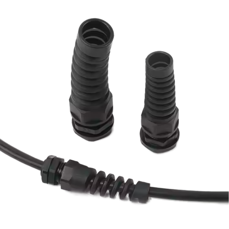
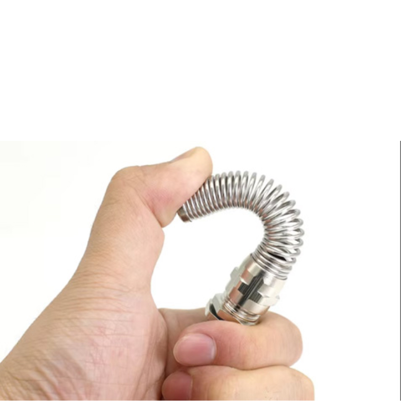
Optimized strain relief geometry distributes bending loads over larger areas, reducing stress concentrations by 60-80%, while flexible boot designs accommodate cable movement without transferring loads to the gland body, progressive stiffness transitions prevent sharp stress gradients, and reinforced thread designs resist fatigue crack initiation, with proper design enabling 10x improvement in flex life compared to standard cable glands.

Strain Relief Optimization
Geometry Principles:
- Gradual stiffness transitions
- Large bend radius maintenance
- Load distribution optimization
- Stress concentration minimization
Design Parameters:
- Relief length: 3-5x cable diameter
- Taper angle: 15-30 degrees
- Wall thickness variation
- Material selection criteria
Performance Benefits:
- Reduced cable stress
- Extended flex life
- Improved reliability
- Lower maintenance costs
Flexible Boot Design
Boot Configuration:
- Accordion-style flexibility
- Progressive stiffness design
- Multi-durometer construction
- Integrated strain relief
Material Selection:
- Thermoplastic elastomers
- Flexible polyurethanes
- Silicone compounds
- Custom formulations
Performance Characteristics:
- High flex cycle capability
- Environmental resistance
- Tear strength retention
- Long-term durability
Thread Design Optimization
Fatigue-Resistant Features:
- Rolled thread manufacturing
- Optimized root radius
- Surface finish improvement
- Stress concentration reduction
Thread Specifications:
- Pitch optimization
- Engagement length
- Load distribution
- Manufacturing tolerances
Quality Control:
- Thread inspection protocols
- Dimensional verification
- Surface finish measurement
- Performance validation
Progressive Stiffness Design
Stiffness Transition:
- Gradual modulus change
- Multi-material construction
- Engineered flexibility zones
- Stress gradient management
Implementation Methods:
- Variable wall thickness
- Material property gradients
- Geometric transitions
- Composite construction
Performance Advantages:
- Smooth load transfer
- Reduced stress peaks
- Extended fatigue life
- Improved reliability
At Bepto, we incorporate advanced strain relief designs, flexible boot systems, and optimized thread geometry in our high-flex cable glands, providing customers with solutions that achieve 10+ million flex cycles while maintaining IP ratings and electrical performance in demanding automation applications.
Design Validation Process
Prototype Testing:
- Flex life evaluation
- Stress analysis
- Performance verification
- Design optimization
Manufacturing Integration:
- Production feasibility
- Quality control systems
- Cost optimization
- Scalability assessment
Field Performance:
- Customer validation
- Real-world testing
- Performance monitoring
- Continuous improvement
What Testing Methods Evaluate Cable Gland Fatigue Life?
Standardized testing methods provide reliable evaluation of cable gland fatigue performance in high-flex applications.
IEC 615375 cable tray flexing tests simulate real-world conditions with controlled bend radius and cycle frequency, while custom fatigue testing protocols replicate specific application requirements including multi-axis movement, environmental conditioning, and accelerated aging, with proper testing enabling accurate service life prediction and design optimization for demanding high-flex applications.
Standard Test Protocols
IEC 61537 Flexing Test:
- Bend radius: 10x cable diameter
- Cycle frequency: 60 cycles/minute
- Test duration: Variable
- Performance criteria: No cable damage
Test Setup Requirements:
- Controlled bend geometry
- Consistent loading conditions
- Environmental conditioning
- Continuous monitoring
Performance Evaluation:
- Visual inspection protocols
- Electrical continuity testing
- Mechanical integrity assessment
- Seal performance verification
Custom Application Testing
Multi-Axis Flexing:
- Combined bending and twisting
- Complex motion profiles
- Real-world simulation
- Application-specific conditions
Environmental Conditioning:
- Temperature cycling
- Humidity exposure
- Chemical compatibility
- UV radiation effects
Accelerated Testing:
- Elevated stress levels
- Increased cycle frequency
- Temperature acceleration
- Time compression methods
Test Parameter Selection
Bend Radius Determination:
- Application requirements
- Cable specifications
- Installation constraints
- Performance targets
Cycle Frequency:
- Equipment operating speed
- Duty cycle considerations
- Acceleration factors
- Test duration optimization
Environmental Conditions:
- Operating temperature range
- Humidity levels
- Chemical exposure
- Contamination effects
Data Analysis Methods
Statistical Evaluation:
- Weibull distribution analysis
- Confidence interval calculation
- Failure mode identification
- Life prediction modeling
Performance Metrics:
- Mean cycles to failure
- Characteristic life values
- Reliability percentiles
- Safety factor determination
Correlation Studies:
- Laboratory vs. field performance
- Accelerated vs. real-time testing
- Environmental factor effects
- Design parameter sensitivity
I worked with Ahmed, a test engineer at a wind turbine manufacturer in Dubai, UAE, where their nacelle cable systems required validation for 20-year service life under continuous wind-induced flexing, requiring comprehensive fatigue testing protocols to ensure reliable operation.
Ahmed’s team developed custom test protocols simulating 25 years of wind loading in 6 months, validating our high-flex cable glands through 15 million cycles while maintaining IP65 protection and electrical continuity, providing confidence for their critical renewable energy applications.
Quality Assurance Integration
Production Testing:
- Sample lot validation
- Process control verification
- Performance consistency
- Documentation requirements
Field Correlation:
- Installation monitoring
- Performance tracking
- Failure analysis
- Model refinement
Continuous Improvement:
- Design optimization
- Material enhancement
- Process refinement
- Customer feedback integration
How Do You Select Cable Glands for High-Flex Applications?
Proper selection requires careful analysis of application requirements, environmental conditions, and performance expectations.
Selection criteria must consider flex cycle requirements, bend radius limitations, environmental conditions, and cable specifications, while material selection balances fatigue resistance with chemical compatibility and temperature capability, and design features must accommodate specific motion profiles and installation constraints, requiring detailed application analysis and supplier consultation to ensure optimal performance and reliability.
Application Analysis Framework
Motion Profile Assessment:
- Flex cycle frequency
- Bend radius requirements
- Multi-axis movement
- Duty cycle patterns
Environmental Conditions:
- Temperature extremes
- Chemical exposure
- Contamination levels
- UV radiation
Performance Requirements:
- Service life expectations
- Reliability targets
- Maintenance intervals
- Failure consequences
Selection Criteria Matrix
Primary Factors:
| Factor | High Priority | Medium Priority | Low Priority |
|---|---|---|---|
| Flex Cycles | >5 million | 1-5 million | <1 million |
| Environment | Harsh | Moderate | Benign |
| Reliability | Critical | Important | Standard |
| Cost | Premium | Balanced | Economy |
Material Selection Guide
Standard Applications:
- PA66 glass reinforced bodies
- TPE flexible seals
- Stainless steel hardware
- Standard strain relief
Demanding Applications:
- Specialized polymer compounds
- High-performance elastomers
- Premium metal alloys
- Advanced strain relief designs
Extreme Applications:
- Custom material formulations
- Multi-component designs
- Engineered solutions
- Comprehensive testing validation
Design Feature Requirements
Strain Relief Specifications:
- Length requirements
- Flexibility characteristics
- Load distribution capability
- Environmental compatibility
Seal System Design:
- Flexibility requirements
- Environmental resistance
- Compression characteristics
- Service life expectations
Thread Specifications:
- Fatigue resistance
- Installation requirements
- Load capacity
- Corrosion resistance
Supplier Evaluation Criteria
Technical Capabilities:
- Design expertise
- Material knowledge
- Testing capabilities
- Application experience
Quality Assurance:
- Manufacturing standards
- Testing protocols
- Certification compliance
- Performance guarantees
Support Services:
- Application engineering
- Technical consultation
- Installation support
- After-sales service
At Bepto, we provide comprehensive application analysis and material selection guidance, helping customers choose optimal cable gland solutions for their specific high-flex requirements while ensuring cost-effective designs that meet all performance and reliability expectations.
Implementation Best Practices
Installation Guidelines:
- Proper bend radius maintenance
- Strain relief positioning
- Environmental protection
- Documentation requirements
Maintenance Protocols:
- Inspection schedules
- Performance monitoring
- Preventive replacement
- Failure analysis procedures
Performance Optimization:
- Operating parameter adjustment
- Environmental control
- Load minimization
- Life extension strategies
Conclusion
Cable gland fatigue life in high-flex applications depends critically on material selection, design optimization, and proper application analysis. Engineering plastics like PA66 with glass reinforcement provide excellent fatigue resistance, while TPE seals offer superior flex life performance. Specialized design features including optimized strain relief, flexible boots, and fatigue-resistant thread geometry can improve flex life by 10x compared to standard designs. Proper testing using IEC 61537 protocols and custom application-specific methods enables accurate performance prediction and design validation. Selection requires careful analysis of flex cycle requirements, environmental conditions, and performance expectations, with material and design choices balanced against cost and reliability targets. Quality suppliers provide comprehensive application support, testing validation, and performance guarantees for demanding high-flex applications. At Bepto, we offer advanced high-flex cable gland solutions with superior materials, optimized designs, and comprehensive testing validation to ensure reliable performance exceeding 10 million flex cycles in demanding automation and mobile equipment applications. Remember, investing in proper fatigue-resistant cable glands prevents costly equipment failures and production downtime in critical high-flex applications! 😉
FAQs About Cable Gland Fatigue Life
Q: How many flex cycles can cable glands handle?
A: High-quality cable glands designed for flex applications can handle 5-10 million cycles, while standard glands typically fail within 500,000-1 million cycles. Fatigue life depends on bend radius, cycle frequency, environmental conditions, and material selection.
Q: What causes cable glands to fail in flexing applications?
A: Fatigue failure occurs from repeated mechanical stress creating microscopic cracks that propagate over time. Stress concentrations at thread roots, inadequate strain relief, and poor material selection accelerate crack growth and premature failure.
Q: Which materials are best for high-flex cable glands?
A: PA66 with glass reinforcement offers excellent fatigue resistance for bodies, while TPE (thermoplastic elastomer) seals provide superior flex life. Stainless steel hardware with optimized geometry resists crack initiation and propagation.
Q: How do I calculate required flex life for my application?
A: Multiply equipment operating cycles per hour by daily operating hours, then by expected service life in years. Add safety factors of 2-5x depending on criticality. For example: 60 cycles/hour × 16 hours × 365 days × 10 years × 3 safety factor = 10.5 million cycles.
Q: Can standard cable glands be used in flexing applications?
A: Standard cable glands are not suitable for continuous flexing and will fail quickly. High-flex applications require specialized designs with optimized strain relief, flexible materials, and fatigue-resistant construction to achieve acceptable service life.
-
Explore the fundamental engineering principles of how materials weaken under repeated stress. ↩
-
Understand how geometric shapes can concentrate stress and accelerate material failure. ↩
-
Delve into the science of how chemical exposure can cause plastics to crack under stress. ↩
-
Learn about the unique properties of TPEs that make them ideal for high-flexibility applications. ↩
-
Review the official international standard for cable management systems, including testing protocols. ↩
