Inadequate sealing in Ex p pressurized systems leads to catastrophic pressure loss, explosive atmosphere ingress, equipment failure, and potential explosions that can destroy facilities, cause fatalities, and result in millions in damages, making proper cable gland selection and installation absolutely critical for maintaining the positive pressure that prevents hazardous gases from entering electrical enclosures in explosive environments.
Cable glands in Ex p1 systems must provide gas-tight sealing to maintain positive internal pressure above atmospheric levels, preventing explosive gas ingress through certified designs that meet IEC 60079-22 and ATEX standards3, using specialized sealing compounds, multiple barrier systems, and pressure monitoring integration to ensure continuous protection in Zone 1 and Zone 2 hazardous areas4.
Having designed pressurization systems for offshore oil platforms and chemical processing facilities worldwide, I’ve seen firsthand how critical proper cable gland sealing is for Ex p system integrity. Let me share the essential knowledge that ensures your pressurized enclosures maintain life-saving protection in explosive atmospheres.
Table of Contents
- What Are Ex p Pressurized Systems and Why Do They Need Special Glands?
- How Do Cable Glands Maintain Gas-Tight Sealing in Pressurized Enclosures?
- What Standards and Certifications Must Ex p Cable Glands Meet?
- How Do You Select and Install Cable Glands for Ex p Applications?
- What Maintenance and Testing Procedures Ensure Long-Term Reliability?
- FAQs About Ex p Cable Glands
What Are Ex p Pressurized Systems and Why Do They Need Special Glands?
Ex p pressurized systems maintain positive internal pressure in electrical enclosures to prevent explosive gas ingress, requiring specialized cable glands that provide gas-tight sealing without compromising the pressure barrier, using advanced sealing technologies, certified materials, and integrated pressure monitoring to ensure continuous protection in hazardous areas where conventional protection methods are insufficient or impractical.
Understanding Ex p principles is fundamental to proper cable gland selection and system design.
Ex p Protection Principle
Positive Pressure Maintenance: Ex p systems maintain internal pressure typically 25-500 Pa above atmospheric pressure to prevent explosive gas ingress.
Continuous Air/Inert Gas Flow: Fresh air or inert gas continuously flows through the enclosure, diluting any gas that might enter and maintaining positive pressure.
Pressure Monitoring: Sophisticated monitoring systems detect pressure loss and activate alarms or shutdown procedures to maintain safety.
Zone Classification Compatibility: Ex p protection allows normal electrical equipment to operate safely in Zone 1 and Zone 2 hazardous areas.
Critical Sealing Requirements
Gas-Tight Integrity: Cable glands must prevent any gas leakage that could compromise internal pressure or allow explosive atmosphere ingress.
Pressure Differential Resistance: Sealing systems must withstand continuous pressure differentials without degradation or failure.
Temperature Stability: Sealing materials must maintain integrity across operating temperature ranges while under pressure stress.
Chemical Compatibility: Resistance to process chemicals and cleaning agents that could degrade sealing performance.
System Integration Challenges
Multiple Cable Entries: Large enclosures require numerous cable entries, each representing a potential leak path that must be perfectly sealed.
Cable Movement: Thermal expansion, vibration, and mechanical stress can affect cable gland sealing integrity over time.
Maintenance Access: Sealing systems must allow for maintenance activities without compromising long-term pressure integrity.
Emergency Shutdown: Integration with emergency systems that may require rapid pressure changes or system isolation.
Application Areas Requiring Ex p Protection
Offshore Oil Platforms: Drilling and production equipment in marine environments with hydrocarbon vapors.
Chemical Processing: Reactor control rooms and analyzer houses in facilities handling flammable chemicals.
Refineries: Control buildings and electrical rooms in areas with potential hydrocarbon releases.
Pharmaceutical Manufacturing: Clean rooms and control systems handling flammable solvents and compounds.
Mining Operations: Electrical equipment in areas with methane or coal dust hazards.
Consequences of Sealing Failure
| Failure Mode | Immediate Risk | Long-term Consequences | Safety Impact |
|---|---|---|---|
| Pressure Loss | System shutdown | Equipment damage | Production loss |
| Gas Ingress | Explosion risk | Facility destruction | Potential fatalities |
| Seal Degradation | Gradual failure | Maintenance costs | Reduced reliability |
| Monitoring Failure | Undetected hazards | Regulatory violations | Legal liability |
David, a project manager at a North Sea oil platform in Aberdeen, Scotland, faced critical pressure loss issues in their main control room Ex p system. Multiple cable gland failures were causing pressure drops that triggered emergency shutdowns, costing $50,000 per hour in lost production. We provided specialized Ex p-certified cable glands with dual-barrier sealing that eliminated all pressure leaks and have maintained perfect integrity through two years of harsh marine conditions. 😊
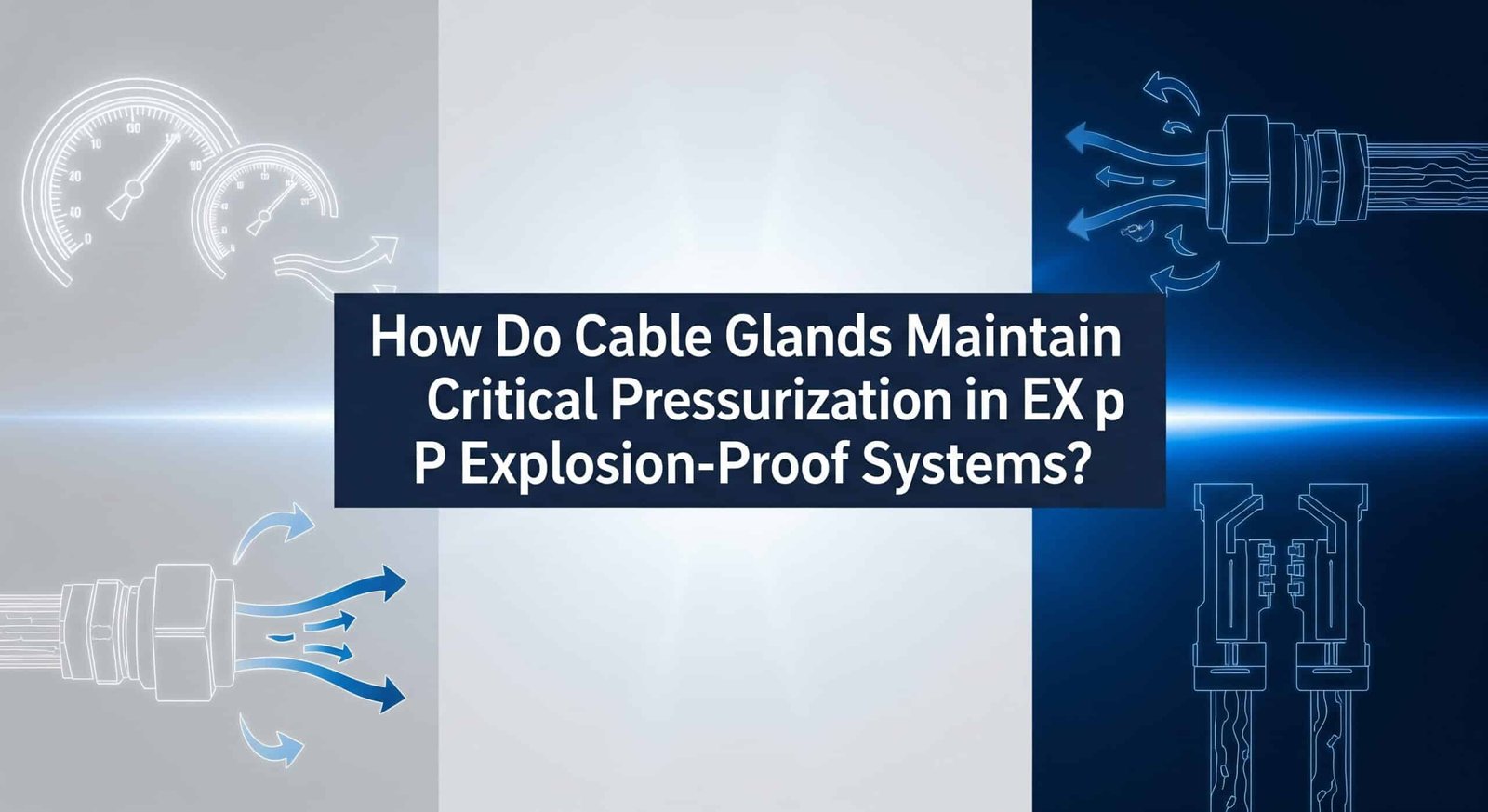
How Do Cable Glands Maintain Gas-Tight Sealing in Pressurized Enclosures?
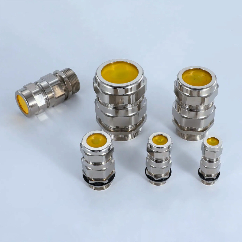
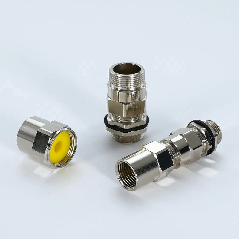
Cable glands maintain gas-tight sealing in Ex p systems through multi-stage sealing barriers including primary elastomer seals, secondary backup seals, and sealing compound injection systems, combined with precision-machined surfaces, controlled compression ratios, and specialized materials that resist pressure cycling and chemical exposure while providing measurable leak rates below 0.1 mbar·l/s to ensure continuous pressurization integrity.
Advanced sealing technology is essential for reliable Ex p system operation.
Multi-Barrier Sealing Systems
Primary Sealing Stage: High-performance elastomer seals provide the main pressure barrier with controlled compression and surface contact.
Secondary Backup Seals: Independent backup sealing elements activate if primary seals degrade, ensuring continued protection.
Tertiary Sealing Compounds: Injectable sealing compounds fill microscopic gaps and provide additional leak protection.
Mechanical Compression Systems: Precision-controlled compression mechanisms ensure optimal sealing force without over-stressing components.
Advanced Sealing Materials
EPDM Elastomers: Excellent chemical resistance and temperature stability for long-term sealing performance.
Fluorocarbon Seals: Superior chemical compatibility and low permeability for critical applications.
Silicone Compounds: Flexible sealing materials that maintain properties across wide temperature ranges.
Specialized Sealants: Custom-formulated compounds designed for specific chemical environments and pressure conditions.

Pressure-Resistant Design Features
Reinforced Construction: Heavy-duty materials and construction methods resist pressure-induced stress and deformation.
Balanced Pressure Design: Internal design features that minimize pressure-induced stress on sealing components.
Expansion Compensation: Design elements that accommodate thermal expansion without compromising sealing integrity.
Stress Distribution: Optimized geometry distributes mechanical stress to prevent seal failure points.
Leak Detection Integration
Pressure Monitoring Ports: Integrated monitoring points allow continuous pressure measurement and leak detection.
Test Gas Injection: Capability for helium leak testing and periodic seal integrity verification.
Flow Measurement: Integration with flow measurement systems to detect seal degradation trends.
Alarm Integration: Connection to safety systems for immediate notification of sealing failures.
Installation and Commissioning
Surface Preparation: Critical surface preparation requirements to ensure optimal sealing contact.
Torque Specifications: Precise torque requirements to achieve proper seal compression without damage.
Leak Testing Procedures: Comprehensive leak testing using helium mass spectrometry5 or pressure decay methods.
Documentation Requirements: Detailed records of installation parameters and test results for regulatory compliance.
Performance Monitoring
Continuous Pressure Monitoring: Real-time monitoring of enclosure pressure to detect seal degradation.
Periodic Leak Testing: Scheduled leak testing to verify continued sealing performance.
Seal Condition Assessment: Regular inspection of seal condition and replacement scheduling.
Performance Trending: Long-term tracking of sealing performance to optimize maintenance intervals.
Common Sealing Challenges
Temperature Cycling: Repeated temperature changes stress sealing materials and can cause premature failure.
Chemical Exposure: Process chemicals and cleaning agents can degrade sealing materials over time.
Mechanical Stress: Vibration and cable movement create dynamic stress that affects seal longevity.
Aging Effects: Long-term exposure to pressure and environmental conditions gradually degrades sealing performance.
What Standards and Certifications Must Ex p Cable Glands Meet?
Ex p cable glands must meet IEC 60079-2 international standards for pressurized enclosures, ATEX Directive 2014/34/EU for European markets, NEC Article 500 for North American applications, and additional standards including IP65/66 environmental protection, temperature classification requirements, and third-party certification from recognized bodies like BASEEFA, CSA, or UL to ensure safety and regulatory compliance in hazardous area installations.
Compliance with multiple standards is mandatory for Ex p applications.
International Standards Framework
IEC 60079-2 Pressurized Enclosures: Primary international standard defining requirements for Ex p equipment design, testing, and installation.
IEC 60079-0 General Requirements: Fundamental requirements for all explosion-proof equipment including marking, documentation, and quality assurance.
IEC 60079-14 Installation: Installation requirements for electrical equipment in hazardous areas including cable gland specifications.
ISO 80079-36 Non-electrical Equipment: Requirements for non-electrical components in Ex p systems including mechanical components.
Regional Certification Requirements
ATEX Directive (Europe): European directive requiring CE marking and notified body certification for hazardous area equipment.
NEC/CEC (North America): National Electrical Code and Canadian Electrical Code requirements for hazardous location installations.
IECEx Scheme: International certification scheme providing global acceptance of explosion-proof equipment.
Local Approvals: Country-specific approvals required for many international markets including Brazil, Russia, and China.
Performance Testing Requirements
Pressure Testing: Verification of sealing performance under specified pressure differentials and cycling conditions.
Temperature Testing: Performance verification across rated temperature ranges including thermal cycling effects.
Chemical Compatibility: Testing with relevant chemicals and cleaning agents to verify long-term compatibility.
Mechanical Testing: Vibration and mechanical stress testing to simulate real-world installation conditions.
Documentation and Marking
Certificate of Conformity: Official certification documents from recognized testing laboratories and certification bodies.
Technical Documentation: Detailed technical files including test reports, drawings, and installation instructions.
Product Marking: Specific marking requirements including Ex marking, temperature class, and certification body identification.
Installation Instructions: Comprehensive installation and maintenance instructions for proper system integration.
Quality Assurance Requirements
ISO 9001 Quality Management: Quality management system certification ensuring consistent manufacturing processes.
Production Surveillance: Ongoing factory inspections and product testing to maintain certification validity.
Change Control: Formal procedures for managing product changes that might affect certification status.
Traceability Systems: Complete traceability of materials and manufacturing processes for quality control.
Certification Body Recognition
BASEEFA (UK): British certification body with global recognition for explosion-proof equipment.
CSA (Canada): Canadian Standards Association providing North American market access.
UL (USA): Underwriters Laboratories certification for US market compliance.
TÜV (Germany): German technical inspection association providing European and global certifications.
DEKRA (Netherlands): International certification body specializing in safety and environmental protection.
Ongoing Compliance Requirements
Certificate Maintenance: Regular surveillance audits and testing to maintain certification validity.
Standard Updates: Compliance with updated standards and regulations as they are revised.
Market Surveillance: Response to market surveillance activities and regulatory inquiries.
Incident Reporting: Mandatory reporting of any safety incidents or product defects to certification bodies.
How Do You Select and Install Cable Glands for Ex p Applications?
Selecting and installing Ex p cable glands requires comprehensive hazard area classification analysis, cable type compatibility assessment, environmental condition evaluation, and integration with pressurization system design, followed by certified installer training, precise installation procedures including surface preparation and torque specifications, comprehensive leak testing, and detailed documentation to ensure regulatory compliance and long-term safety performance.
Proper selection and installation are critical for system safety and regulatory compliance.
Hazard Area Assessment
Zone Classification: Determine specific zone classification (Zone 1 or Zone 2) and required equipment protection level.
Gas Group Classification: Identify specific hazardous gases and their classification (IIA, IIB, or IIC) for proper equipment selection.
Temperature Classification: Determine maximum surface temperature requirements based on gas ignition temperatures.
Environmental Conditions: Assess temperature ranges, chemical exposure, and mechanical stress conditions.
Cable Gland Selection Criteria
Pressure Rating: Select glands rated for system operating pressure plus appropriate safety margins.
Cable Compatibility: Ensure compatibility with specific cable types, sizes, and jacket materials.
Material Selection: Choose appropriate materials for chemical compatibility and environmental conditions.
Certification Requirements: Verify all required certifications and approvals for the specific application and market.
Installation Planning and Preparation
System Integration: Coordinate cable gland installation with overall Ex p system design and pressurization equipment.
Installation Sequence: Plan installation sequence to minimize system downtime and maintain safety during construction.
Tool and Equipment Requirements: Specify required tools, testing equipment, and safety equipment for installation.
Personnel Qualification: Ensure installation personnel have appropriate training and certifications for hazardous area work.
Installation Procedures
Surface Preparation: Critical cleaning and preparation of sealing surfaces to ensure optimal performance.
Component Inspection: Thorough inspection of all gland components before installation to verify condition and compatibility.
Assembly Sequence: Follow manufacturer-specified assembly sequence to ensure proper sealing and performance.
Torque Application: Apply specified torque values using calibrated equipment to achieve proper seal compression.
Testing and Commissioning
Initial Leak Testing: Comprehensive leak testing using helium mass spectrometry or pressure decay methods.
Pressure Testing: System pressure testing to verify overall integrity and performance.
Functional Testing: Integration testing with pressurization system and monitoring equipment.
Documentation Completion: Complete all required documentation including test certificates and installation records.
Quality Control Measures
Installation Checklists: Systematic checklists ensuring all installation requirements are met.
Independent Inspection: Third-party inspection and verification of critical installations.
Test Documentation: Comprehensive documentation of all testing activities and results.
Corrective Action Procedures: Established procedures for addressing any deficiencies discovered during testing.
Common Installation Mistakes
Inadequate Surface Preparation: Poor surface preparation compromises sealing performance and system integrity.
Incorrect Torque Application: Improper torque can damage sealing components or create leak paths.
Component Contamination: Contamination during installation creates leak paths and reduces reliability.
Incomplete Testing: Inadequate testing fails to identify problems before system commissioning.
Hassan, who manages a petrochemical facility in Jubail, Saudi Arabia, needed to upgrade their analyzer house Ex p system with new cable glands that could handle extreme desert temperatures and corrosive process chemicals. The existing glands were failing leak tests due to seal degradation from heat and chemical exposure. We provided specialized fluorocarbon-sealed Ex p glands with enhanced temperature ratings that have maintained perfect leak-tight performance through 18 months of operation in temperatures exceeding 55°C.
What Maintenance and Testing Procedures Ensure Long-Term Reliability?
Long-term reliability of Ex p cable glands requires systematic preventive maintenance including periodic leak testing using helium detection or pressure decay methods, seal condition monitoring, environmental exposure assessment, documentation of performance trends, scheduled replacement based on service life data, and integration with overall Ex p system maintenance to ensure continuous pressurization integrity and regulatory compliance throughout the equipment lifecycle.
Proactive maintenance prevents failures and ensures continued safety performance.
Preventive Maintenance Programs
Risk-Based Scheduling: Maintenance intervals based on criticality, environmental exposure, and historical performance data.
Condition Monitoring: Regular assessment of seal condition, pressure performance, and environmental factors.
Performance Trending: Long-term tracking of key performance indicators to optimize maintenance timing.
Predictive Maintenance: Use of advanced monitoring techniques to predict seal degradation before failure occurs.
Leak Testing Procedures
Helium Leak Detection: Precision leak testing using helium mass spectrometry for maximum sensitivity.
Pressure Decay Testing: System pressure testing to identify gross leaks and overall system integrity.
Bubble Testing: Visual leak detection using soap solutions for accessible installations.
Differential Pressure Monitoring: Continuous monitoring of pressure differentials to detect gradual seal degradation.
Inspection and Assessment
Visual Inspection: Regular visual inspection of cable glands for signs of damage, corrosion, or degradation.
Seal Condition Assessment: Detailed evaluation of sealing component condition and replacement needs.
Environmental Impact Evaluation: Assessment of environmental factors affecting seal performance and longevity.
System Integration Review: Verification of proper integration with pressurization and monitoring systems.
Documentation and Record Keeping
Maintenance Logs: Detailed records of all maintenance activities, findings, and corrective actions.
Test Records: Comprehensive documentation of all testing activities and results.
Performance History: Long-term tracking of seal performance and failure patterns.
Regulatory Compliance: Documentation supporting ongoing regulatory compliance and audit requirements.
Replacement and Upgrade Procedures
Service Life Management: Systematic replacement based on manufacturer recommendations and service experience.
Upgrade Planning: Integration of improved technologies and materials as they become available.
Emergency Replacement: Rapid response procedures for critical seal failures affecting system safety.
Obsolescence Management: Planning for component obsolescence and alternative product selection.
Training and Competency
Maintenance Personnel Training: Comprehensive training on Ex p system maintenance and safety requirements.
Certification Requirements: Ensuring maintenance personnel have appropriate certifications for hazardous area work.
Continuous Education: Ongoing training on new technologies, standards, and best practices.
Safety Procedures: Emphasis on safety procedures and risk management during maintenance activities.
Performance Optimization
Failure Analysis: Root cause analysis of seal failures to improve future performance and maintenance practices.
Technology Updates: Incorporation of new sealing technologies and improved materials.
Process Improvement: Continuous improvement of maintenance procedures based on experience and industry best practices.
Cost Optimization: Balancing maintenance costs with reliability requirements and safety performance.
Conclusion
Cable glands play a critical role in maintaining pressurization integrity in Ex p explosion-proof systems, requiring specialized designs, rigorous certification, and comprehensive maintenance programs. Success depends on understanding the unique requirements of pressurized systems and implementing proven selection, installation, and maintenance practices.
The key to reliable Ex p cable gland performance lies in proper specification, quality installation, and proactive maintenance. At Bepto, we provide certified Ex p cable glands and comprehensive technical support to help ensure your pressurized systems maintain critical safety protection in hazardous environments.
FAQs About Ex p Cable Glands
Q: What makes Ex p cable glands different from regular explosion-proof glands?
A: Ex p cable glands provide gas-tight sealing to maintain positive pressure, while regular explosion-proof glands only contain explosions. Ex p glands feature multi-barrier sealing systems, pressure monitoring integration, and specialized materials to prevent any gas leakage that could compromise pressurization.
Q: How often should I test Ex p cable gland sealing performance?
A: Test Ex p cable gland sealing annually as a minimum, with quarterly testing recommended for critical applications. High-risk environments may require monthly testing, while some regulations mandate specific testing intervals based on zone classification and system criticality.
Q: Can I retrofit existing cable glands for Ex p applications?
A: No, existing cable glands cannot be retrofitted for Ex p use. Ex p applications require purpose-designed glands with certified gas-tight sealing, pressure monitoring integration, and specific materials that meet IEC 60079-2 standards from the manufacturing stage.
Q: What leak rate is acceptable for Ex p cable glands?
A: Ex p cable glands must achieve leak rates below 0.1 mbar·l/s when tested according to IEC 60079-2 standards. Many applications require even lower leak rates, with some critical systems specifying maximum leak rates of 0.01 mbar·l/s or less.
Q: Do Ex p cable glands require special installation procedures?
A: Yes, Ex p cable glands require certified installers, specific surface preparation, precise torque specifications, and comprehensive leak testing. Installation must follow manufacturer procedures and relevant standards, with complete documentation required for regulatory compliance and safety certification.
-
Learn about the ‘Pressurized Enclosure’ (Ex p) method of protection, which prevents explosive atmospheres from entering equipment. ↩
-
Review the official scope of the IEC 60079-2 standard, which specifies the requirements for the design and testing of pressurized enclosures. ↩
-
Understand the European Union’s ATEX Directive, which covers equipment and protective systems intended for use in potentially explosive atmospheres. ↩
-
Explore the IEC zone classification system used to define hazardous areas based on the frequency and duration of an explosive atmosphere. ↩
-
Discover the principles of helium mass spectrometry, a highly sensitive method used to detect and measure minute leaks in sealed systems. ↩
