Poor strain relief causes cable failure while inadequate sealing allows moisture ingress. Both failures lead to equipment damage and safety hazards.
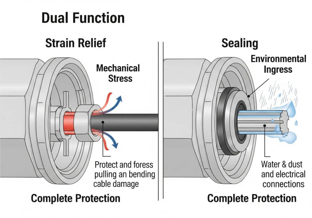
Cable glands provide dual protection through mechanical strain relief that prevents cable damage and environmental sealing that blocks moisture, dust, and contaminants. Proper design balances both functions without compromising either.
David’s production line suffered three cable failures last month before he understood that his glands were sealing perfectly but providing zero strain relief protection.
Table of Contents
- What’s the Difference Between Strain Relief and Sealing Functions?
- How Does Cable Gland Design Achieve Both Functions Simultaneously?
- Which Applications Prioritize Strain Relief vs. Sealing Performance?
- What Are the Common Failures When One Function Is Compromised?
What’s the Difference Between Strain Relief and Sealing Functions?
Understanding these distinct functions prevents installation mistakes and ensures complete cable protection in your applications.
Strain relief protects cables from mechanical stress through grip and support, while sealing prevents environmental ingress through compression and barriers. Both functions use different mechanisms but work together for complete protection.
Strain Relief Function Explained
Strain relief protects cables from mechanical damage:
Primary Protection Mechanisms
- Grip force: Prevents cable pullout under tension
- Bend radius control: Maintains minimum bend radius
- Stress distribution: Spreads loads across cable length
- Vibration damping1: Reduces fatigue from movement
Critical Performance Parameters
- Pull-out force: Measured in Newtons (N) or pounds-force (lbf)
- Grip range: Cable diameter accommodation range
- Bend radius: Minimum allowable cable curvature
- Dynamic rating: Cycles before fatigue failure
Sealing Function Fundamentals
Environmental sealing blocks contamination:
Sealing Mechanisms
- Compression sealing: O-rings and gaskets under pressure
- Interference fit: Tight tolerances between components
- Multiple barriers: Redundant sealing points
- Material compatibility: Chemical resistance matching
Sealing Performance Standards
- IP ratings: IP54, IP65, IP66, IP67, IP68 protection levels
- Pressure resistance: Positive and negative pressure capability
- Temperature stability: Seal integrity across temperature range
- Chemical resistance: Compatibility with process fluids
Hassan’s chemical plant requires IP68 sealing for underwater cable runs, but also needs 500N pull-out resistance for thermal expansion stress. We designed custom glands meeting both requirements.
Function Interaction Analysis
Complementary Effects
When properly designed:
- Strain relief reduces seal stress: Less movement preserves sealing integrity
- Good sealing protects strain relief components: Prevents corrosion and degradation
- Balanced compression: Optimal force for both functions
Potential Conflicts
Design challenges include:
- Over-compression: Damages cable while improving seal
- Under-compression: Poor sealing but preserved cable integrity
- Material selection: Different requirements for each function
Performance Measurement Methods
Strain Relief Testing
We conduct comprehensive testing:
- Pull-out tests: Gradual force application to failure
- Cyclic loading: Repeated stress application
- Bend testing: Minimum radius verification
- Fatigue analysis: Long-term performance prediction
Sealing Verification
Our sealing tests include:
- Pressure testing: Positive and negative pressure application
- Immersion testing: Underwater performance verification
- Spray testing: Directional water jet resistance
- Dust testing: Particulate ingress prevention
How Does Cable Gland Design Achieve Both Functions Simultaneously?
Integrated design principles ensure both strain relief and sealing work together without compromising either function.
Multi-component gland design uses separate elements for each function: clamping rings for strain relief and sealing rings for environmental protection. Proper assembly sequence and torque values optimize both functions simultaneously.
Component-Based Design Architecture
Strain Relief Components
Dedicated mechanical elements:
Clamping Ring System
- Segmented design: Distributes clamping force evenly
- Material selection: Steel or brass for high grip force
- Surface texture: Knurled or serrated for enhanced grip
- Compression ratio: Optimized for cable diameter range
Cable Armor Gripping
For armored cables:
- Armor cone: Spreads individual wire loads
- Compression fitting: Secures armor termination
- Earth continuity: Maintains electrical connection
- Corrosion protection: Prevents galvanic reactions2
Sealing Component Integration
Primary Sealing Elements
Environmental protection components:
O-Ring Sealing System
- Multiple sealing points: Thread, cable entry, and body seals
- Material compatibility: NBR, EPDM, Viton selection
- Compression optimization: 15-25% compression ratio
- Backup seals: Redundant protection for critical applications
Cable Entry Sealing
- Compression glands: Adjustable cable diameter accommodation
- Insert systems: Pre-formed sealing elements
- Gel-filled options: Self-sealing around irregular cables
- Multi-cable sealing: Single gland for multiple cables
David’s team initially struggled with our multi-component glands until we provided assembly training. Now they achieve consistent IP67 rating with 300N pull-out strength across all installations.
Assembly Sequence Optimization
Critical Installation Steps
Proper assembly ensures both functions:
Step 1: Component Preparation
- Thread inspection: Clean and lubricate threads
- O-ring installation: Proper groove placement
- Cable preparation: Strip and clean cable end
- Diameter verification: Confirm cable size compatibility
Step 2: Strain Relief Assembly
- Clamping ring positioning: Correct cable location
- Initial compression: Hand-tight assembly
- Alignment verification: Straight cable entry
- Torque application: Specified values for grip force
Step 3: Sealing Finalization
- Sealing ring compression: Gradual, even tightening
- Torque sequence: Multiple passes to specification
- Verification testing: Pressure or vacuum testing
- Final inspection: Visual and dimensional checks
Advanced Design Features
Integrated Solutions
Modern gland designs incorporate:
Progressive Compression
- Staged tightening: Separate adjustment for each function
- Visual indicators: Compression level verification
- Torque limiting: Prevents over-compression damage
- Field adjustability: Service access for maintenance
Smart Sealing Technology
- Self-adjusting seals: Accommodate cable movement
- Temperature compensation: Maintains seal integrity
- Pressure equalization: Prevents seal extrusion
- Monitoring capability: Seal condition indication
Hassan’s offshore platform uses our progressive compression glands that maintain IP68 sealing while allowing thermal expansion movement of 50mm without stress on the cables.
Material Engineering Considerations
Dual-Function Materials
Optimized material selection:
Elastomer Selection
- Hardness optimization: Balance between sealing and flexibility
- Chemical resistance: Process fluid compatibility
- Temperature range: Maintains properties across extremes
- Compression set3: Long-term sealing integrity
Metal Component Design
- Strength requirements: Adequate for maximum loads
- Corrosion resistance: Environmental compatibility
- Thermal expansion: Matching coefficients with cables
- Electrical properties: EMC and grounding requirements
Which Applications Prioritize Strain Relief vs. Sealing Performance?
Different industries and applications require emphasis on specific functions based on environmental conditions and operational requirements.
High-vibration applications prioritize strain relief performance, while underwater or chemical environments emphasize sealing integrity. Critical applications require maximum performance in both functions with appropriate safety margins.
Strain Relief Priority Applications
High-Vibration Environments
Applications requiring maximum mechanical protection:
Industrial Machinery
- CNC machines: Continuous movement and vibration
- Conveyor systems: Constant motion and acceleration
- Packaging equipment: Rapid cycling operations
- Robotics: Multi-axis movement patterns
Performance requirements:
- Pull-out force: 500-1000N minimum
- Bend radius: 6x cable diameter maximum
- Fatigue life: 1 million cycles minimum
- Temperature cycling: -20°C to +80°C
Transportation Applications
- Railway systems: Shock and vibration from track irregularities
- Marine vessels: Wave motion and engine vibration
- Automotive: Engine vibration and road shock
- Aerospace: Flight loads and pressurization cycles
David’s automated assembly line experienced cable failures every 6 months until we upgraded to high-grip strain relief glands. Now they achieve 3+ year service life with continuous operation.
Sealing Priority Applications
Environmental Protection Critical
Applications where contamination prevention is paramount:
Process Industries
- Chemical plants: Corrosive vapor protection
- Pharmaceutical: Contamination prevention
- Food processing: Hygiene maintenance
- Water treatment: Submersion protection
Sealing requirements:
- IP68 rating: Continuous submersion capability
- Chemical resistance: Process-specific compatibility
- Pressure rating: Positive and negative pressure capability
- Temperature stability: Wide operating range
Outdoor Installations
- Solar farms: Weather protection for 25+ years
- Wind turbines: Extreme weather exposure
- Telecommunications: Moisture and dust protection
- Street lighting: Urban environmental challenges
Hassan’s desalination plant requires IP68 sealing for saltwater exposure plus chemical resistance to cleaning agents. Our specialized sealing compounds have maintained integrity for 5 years without replacement.
Balanced Performance Applications
Critical Infrastructure
Applications requiring maximum performance in both functions:
Power Generation
- Nuclear plants: Safety-critical applications
- Hydroelectric: Underwater and high-vibration combination
- Thermal plants: High temperature and pressure
- Renewable energy: Long-term reliability requirements
Oil and Gas
- Offshore platforms: Marine environment plus vibration
- Refineries: Chemical exposure plus mechanical stress
- Pipelines: Thermal cycling plus environmental protection
- Drilling rigs: Extreme conditions requiring both functions
Application-Specific Design Optimization
Performance Tuning Methods
We optimize designs for specific applications:
Vibration Analysis
- Frequency response: Matching natural frequencies
- Damping coefficients: Vibration energy absorption
- Resonance avoidance: Critical frequency identification
- Fatigue modeling: Stress cycle analysis
Environmental Modeling
- Chemical compatibility: Long-term exposure effects
- Temperature cycling: Thermal stress analysis
- Pressure variations: Seal integrity maintenance
- UV exposure: Material degradation prediction
Selection Guidelines
Decision Matrix Approach
Factor weighting for application selection:
| Application Type | Strain Relief Weight | Sealing Weight | Material Priority |
|---|---|---|---|
| High Vibration | 70% | 30% | Mechanical strength |
| Chemical Process | 30% | 70% | Chemical resistance |
| Marine/Offshore | 50% | 50% | Corrosion resistance |
| Food/Pharma | 40% | 60% | Hygiene compatibility |
What Are the Common Failures When One Function Is Compromised?
Understanding failure modes prevents costly equipment damage and helps optimize gland selection for specific applications.
Strain relief failure causes cable fatigue, conductor breakage, and intermittent connections. Sealing failure allows moisture ingress, corrosion, and insulation breakdown. Both failures can create safety hazards and expensive downtime.
Strain Relief Failure Modes
Cable Damage Mechanisms
When strain relief is inadequate:
Conductor Fatigue
- Flexing damage: Repeated bending breaks individual strands
- Stress concentration: Sharp bends create failure points
- Work hardening4: Metal fatigue from cyclic loading
- Progressive failure: Gradual conductor reduction
Insulation Damage
- Abrasion wear: Movement against sharp edges
- Compression damage: Excessive clamping force
- Thermal damage: Heat from resistance increase
- Chemical degradation: Accelerated by stress
David discovered that 80% of his cable failures occurred within 300mm of inadequately strain-relieved gland entries. Upgrading to proper strain relief eliminated these failures completely.
Mechanical Connection Issues
Terminal Stress
- Connection loosening: Vibration loosens terminals
- Contact resistance: Increased resistance from movement
- Arcing: Poor connections create heat and sparks
- Terminal damage: Mechanical stress breaks connections
Cable Pull-Out
- Complete disconnection: Cable separates from equipment
- Partial withdrawal: Intermittent connection problems
- Armor separation: Shielding effectiveness lost
- Safety hazards: Exposed live conductors
Sealing Failure Consequences
Moisture Ingress Problems
When environmental sealing fails:
Electrical Issues
- Insulation breakdown: Reduced dielectric strength5
- Ground faults: Current leakage to earth
- Short circuits: Direct conductor contact
- Arc faults: Dangerous electrical arcing
Corrosion Damage
- Conductor corrosion: Increased resistance and heat
- Terminal corrosion: Connection degradation
- Equipment damage: Internal component corrosion
- Structural damage: Mounting and support corrosion
Hassan’s refinery experienced a $200,000 equipment failure when moisture entered through failed cable gland seals, causing control system corruption during a critical process phase.
Contamination Effects
Particulate Ingress
- Abrasive wear: Dust damages moving parts
- Insulation tracking: Conductive paths form
- Heat buildup: Reduced cooling effectiveness
- Filter clogging: Ventilation system blockage
Chemical Contamination
- Material degradation: Accelerated aging
- Catalytic reactions: Unexpected chemical processes
- Toxic exposure: Safety hazards for personnel
- Product contamination: Quality issues
Failure Detection Methods
Early Warning Signs
Identify problems before catastrophic failure:
Visual Inspection Indicators
- Seal degradation: Cracking, hardening, or swelling
- Cable deformation: Kinking or compression marks
- Corrosion signs: Discoloration or deposits
- Movement evidence: Wear patterns or looseness
Electrical Testing
- Insulation resistance: Megohm testing
- Continuity verification: Conductor integrity
- Ground fault detection: Leakage current measurement
- Thermal imaging: Hot spot identification
Preventive Maintenance Strategies
Inspection Protocols
Regular maintenance prevents failures:
Monthly Checks
- Visual inspection: External condition assessment
- Torque verification: Connection tightness
- Movement assessment: Cable stress evaluation
- Environmental monitoring: Condition changes
Annual Testing
- Pressure testing: Seal integrity verification
- Pull testing: Strain relief effectiveness
- Electrical testing: Complete system verification
- Documentation: Performance trend analysis
David implemented our recommended inspection schedule and reduced cable-related failures by 90% while extending average service life from 2 to 7 years. 😉
Failure Prevention Design
Redundant Protection
- Multiple sealing points: Backup protection
- Over-specification: Safety margins for critical applications
- Material selection: Conservative ratings
- Installation quality: Proper procedures and training
Monitoring Systems
- Condition monitoring: Real-time performance tracking
- Predictive maintenance: Failure prediction algorithms
- Remote monitoring: Continuous surveillance capability
- Alert systems: Early warning notifications
Cost Impact Analysis
Failure Cost Components
Total cost of inadequate gland performance:
Direct Costs
- Replacement materials: Cables and glands
- Labor costs: Installation and repair time
- Equipment damage: Secondary failure costs
- Emergency response: Premium service rates
Indirect Costs
- Production downtime: Lost revenue
- Safety incidents: Injury and liability costs
- Reputation damage: Customer confidence loss
- Regulatory penalties: Compliance violations
Hassan calculated that proper gland selection with 20% higher initial cost delivered 300% ROI through eliminated failures and extended equipment life.
Conclusion
Successful cable gland selection requires understanding both strain relief and sealing functions, their interaction, and application-specific requirements for optimal long-term performance.
FAQs About Cable Gland Strain Relief and Sealing
Q: Can a cable gland provide excellent sealing but poor strain relief?
A: Yes, many glands prioritize sealing over strain relief. This creates cable fatigue failures despite perfect environmental protection. Always verify both functions meet your application requirements.
Q: What’s the minimum pull-out force for adequate strain relief?
A: Minimum pull-out force should be 5-10 times the cable weight plus expected dynamic loads. For typical applications, 100-300N is adequate, but high-vibration environments may require 500-1000N or more.
Q: How do I know if my cable gland sealing has failed?
A: Signs include visible moisture inside enclosures, reduced insulation resistance (below 1 megohm), corrosion around connections, or intermittent electrical faults during wet weather conditions.
Q: Can over-tightening a cable gland damage both functions?
A: Yes, excessive torque can crush cable insulation (compromising strain relief) while deforming sealing elements (reducing sealing effectiveness). Always follow manufacturer torque specifications for optimal performance.
Q: What IP rating do I need for outdoor cable gland applications?
A: Outdoor applications typically require IP65 minimum for weather protection. Marine or wash-down environments need IP67 or IP68. Consider both water ingress and dust protection requirements for your specific environment.
-
Learn the principles of vibration damping and how it is used in mechanical systems to dissipate energy. ↩
-
Understand how galvanic reactions (corrosion) occur between dissimilar metals and the methods to prevent it. ↩
-
See a technical explanation of compression set in elastomers and why it’s a critical property for long-term seals. ↩
-
Explore the material science concept of work hardening (strain hardening) and its effect on metal ductility. ↩
-
Get an introduction to dielectric strength and how it measures an insulating material’s electrical breakdown. ↩