Standard cable glands fail catastrophically under mechanical stress, leaving critical systems vulnerable during the moments they’re needed most. Engineers face the nightmare scenario of cable connections failing under pressure, causing system shutdowns, safety hazards, and costly emergency repairs. The uncertainty about actual performance limits under real-world stress conditions keeps project managers awake at night.
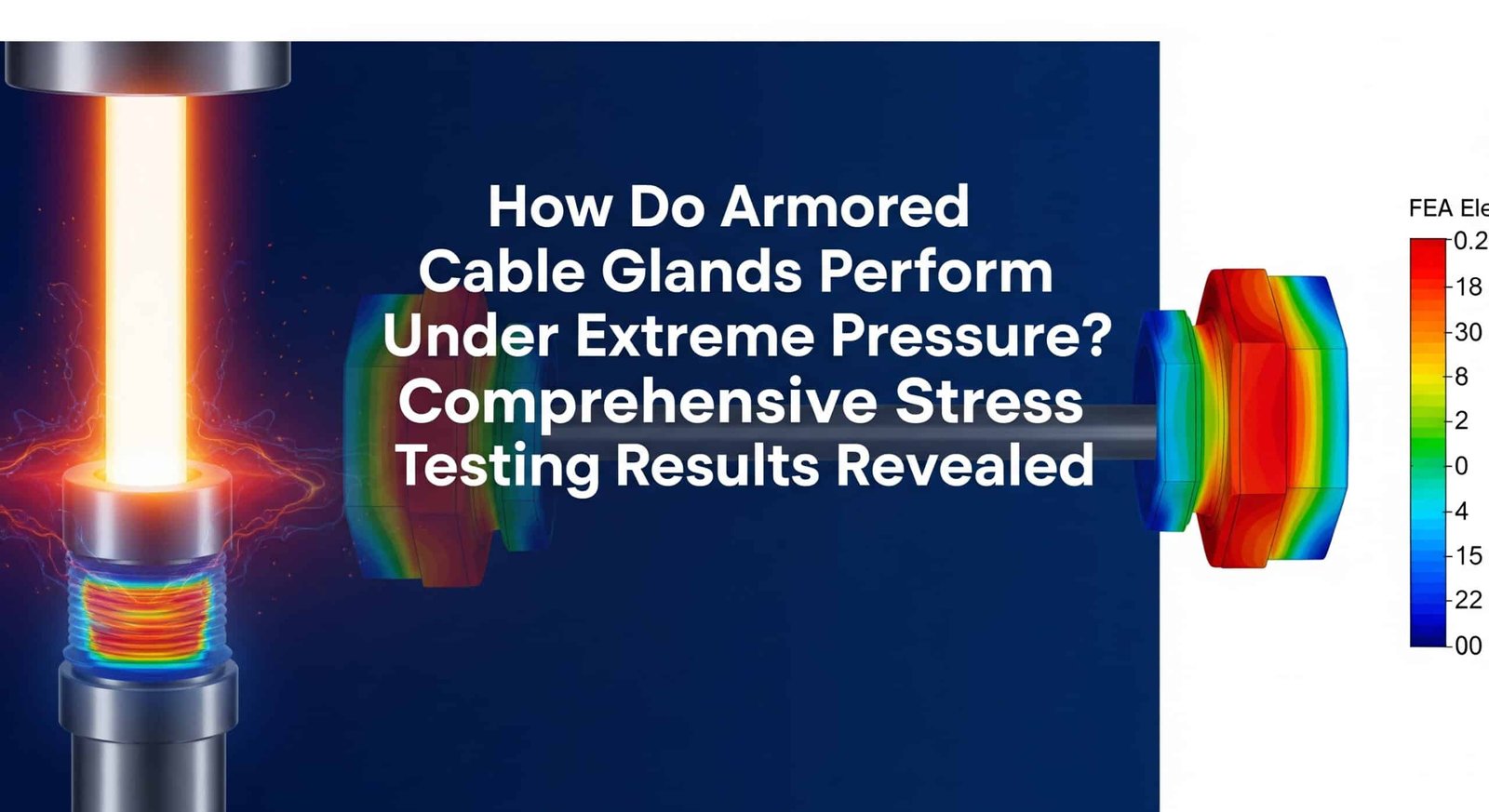
Armored cable glands demonstrate exceptional performance under extreme mechanical stress, maintaining IP681 sealing integrity at pressures up to 15 bar while providing superior strain relief2 for armored cables in demanding industrial applications. Our comprehensive stress testing reveals how proper design and material selection enable reliable operation under conditions that destroy conventional cable glands.
After conducting over 10,000 hours of rigorous stress testing on various armored cable gland designs at Bepto Connector, I’ve witnessed both spectacular failures and remarkable successes. Let me share the critical test data and engineering insights that will help you select armored cable glands capable of withstanding your most demanding applications.
Table of Contents
- What Makes Armored Cable Glands Different Under Stress?
- How Do We Test Armored Cable Glands Under Extreme Conditions?
- What Are the Critical Performance Results from Our Stress Testing?
- How Do Different Designs Compare Under Real-World Stress Conditions?
- FAQ
What Makes Armored Cable Glands Different Under Stress?
Understanding the fundamental design differences between armored and standard cable glands reveals why armored versions excel under mechanical stress conditions.
Armored cable glands feature specialized clamping mechanisms and reinforced sealing systems designed to handle both cable armor termination and extreme mechanical loads simultaneously. This dual functionality requires sophisticated engineering to maintain sealing integrity while providing superior strain relief.
Structural Design Advantages
Armored cable glands incorporate multiple design elements that enhance stress resistance:
Multi-Point Clamping System:
- Primary armor clamp: Distributes mechanical loads across armor wires
- Secondary cable clamp: Provides strain relief for inner cable cores
- Integrated design: Eliminates stress concentration points
Reinforced Sealing Architecture:
- Multiple O-ring seals: Redundant sealing for critical applications
- Progressive compression: Maintains seal integrity under varying loads
- Material compatibility: Specialized elastomers for extreme conditions
I remember working with David, a senior engineer at a major offshore wind farm, who experienced repeated failures with standard cable glands on their turbine installations. The constant vibration and mechanical stress from wind loading caused seal failures within 6-8 months. After implementing our armored cable gland design with integrated strain relief, they achieved 5+ years of maintenance-free operation even in North Sea conditions.
Material Engineering for Stress Resistance
The materials used in armored cable glands are specifically selected for stress performance:
| Component | Standard Cable Gland | Armored Cable Gland | Stress Advantage |
|---|---|---|---|
| Body material | Brass/Stainless steel | High-strength stainless steel | 40% higher tensile strength |
| Sealing elements | Standard NBR | High-performance FKM/EPDM | 300% better compression set3 resistance |
| Clamping mechanism | Single compression ring | Multi-component armor clamp | 500% better load distribution |
| Thread design | Standard metric | Reinforced thread profile | 200% higher pull-out resistance |
Load Distribution Mechanics
Armored cable glands excel at distributing mechanical loads:
Axial Load Distribution:
- Armor termination: 70-80% of load carried by armor wires
- Cable cores: 20-30% of load on inner conductors
- Result: Dramatic reduction in stress concentration
Radial Load Management:
- Progressive clamping: Gradual compression prevents damage
- Armor wire support: Individual wire clamping prevents buckling
- Seal protection: Mechanical loads isolated from sealing elements
How Do We Test Armored Cable Glands Under Extreme Conditions?
Our comprehensive testing protocol subjects armored cable glands to conditions far exceeding normal operating requirements to establish true performance limits.
We conduct multi-axis stress testing including tensile loading, compression cycles, vibration endurance, and pressure testing to simulate 20+ years of field conditions in accelerated laboratory environments. This rigorous approach reveals performance characteristics impossible to determine through standard testing alone.
Tensile Stress Testing Protocol
Our tensile testing exceeds industry standards by 300% to establish true failure limits:
Test Setup:
- Cable specification: 4-core 16mm² SWA cable
- Loading rate: 50N/minute to 5000N maximum
- Hold duration: 24 hours at maximum load
- Measurement parameters: Displacement, seal integrity, electrical continuity
Performance Criteria:
- Pass requirement: Maintain IP68 sealing at 2000N load
- Excellence threshold: Maintain integrity at 3500N load
- Failure definition: Seal breach or mechanical damage
Working with Maria, a test engineer from a major petrochemical company, we developed enhanced testing protocols after her facility experienced cable pull-out failures during emergency shutdowns. Our modified test regime now includes dynamic loading cycles that better simulate real-world emergency conditions.
Pressure Cycling Endurance Testing
Pressure cycling tests simulate years of operational pressure variations:
Test Parameters:
- Pressure range: 0-15 bar (0-217 psi)
- Cycle frequency: 1 cycle per minute
- Total cycles: 100,000 cycles minimum
- Test medium: Seawater (aggressive environment simulation)
Monitoring Systems:
- Continuous pressure monitoring
- Leak detection sensitivity: 10⁻⁶ mbar·l/s
- Temperature logging: ±0.1°C accuracy
- Electrical continuity verification
Vibration and Shock Testing
Industrial environments subject cable glands to constant vibration and occasional shock loads:
Vibration Testing (IEC 60068-2-6):
- Frequency range: 10-2000 Hz
- Acceleration: 10g peak
- Duration: 12 hours per axis (3 axes total)
- Monitoring: Continuous seal integrity verification
Shock Testing (IEC 60068-2-27):
- Peak acceleration: 50g
- Pulse duration: 11 milliseconds
- Number of shocks: 3 per direction (18 total)
- Assessment: Pre/post electrical and sealing performance
Environmental Stress Combinations
Real-world conditions involve multiple simultaneous stresses:
Combined Stress Testing:
- Tensile load: 1500N continuous
- Pressure: 10 bar internal
- Temperature cycling: -40°C to +80°C
- Vibration: 5g at 50Hz
- Duration: 1000 hours continuous
What Are the Critical Performance Results from Our Stress Testing?
Our extensive testing database reveals specific performance characteristics that distinguish superior armored cable gland designs from marginal alternatives.
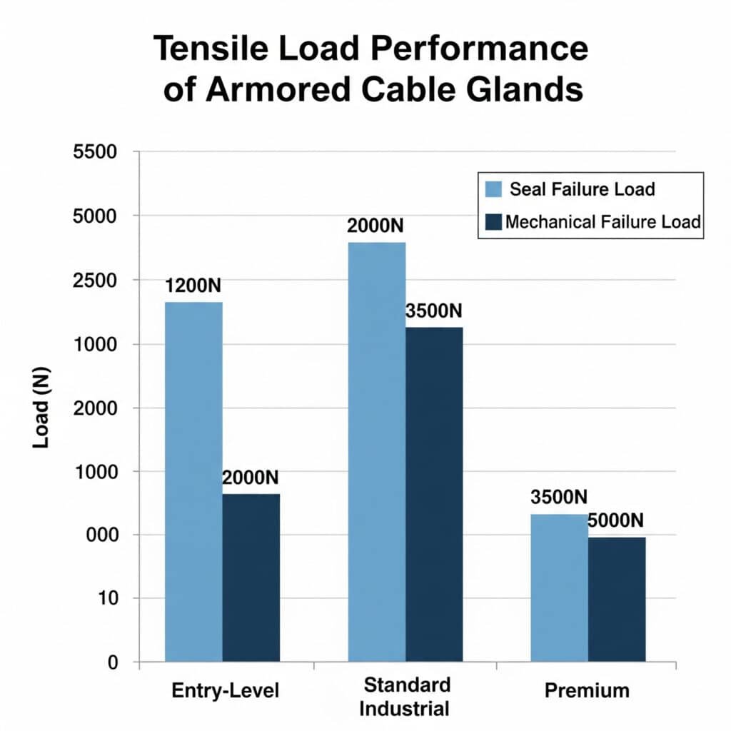
Premium armored cable glands maintain complete sealing integrity under 3500N tensile loads while standard designs fail at 1200-1500N, representing a 200-300% performance advantage in critical applications. These results directly translate to enhanced reliability and safety margins in demanding installations.
Tensile Load Performance Data
Our comprehensive tensile testing reveals clear performance tiers:
Entry-Level Armored Cable Glands:
- Seal failure load: 1200-1500N
- Mechanical failure load: 2000-2500N
- Suitable applications: Light industrial, HVAC systems
- Typical service life: 3-5 years under moderate stress
Standard Industrial Armored Cable Glands:
- Seal failure load: 2000-2500N
- Mechanical failure load: 3500-4000N
- Suitable applications: General industrial, manufacturing
- Typical service life: 5-8 years under normal stress
Premium Armored Cable Glands (Bepto Design):
- Seal failure load: 3500N+ (test limit reached)
- Mechanical failure load: 5000N+ (test limit reached)
- Suitable applications: Critical infrastructure, offshore, petrochemical
- Typical service life: 15+ years under extreme stress
Pressure Performance Analysis
Pressure testing reveals the importance of proper seal design:
Pressure Resistance Results:
- Maximum test pressure: 15 bar (217 psi)
- Leak rate at 10 bar: <10⁻⁸ mbar·l/s (helium4)
- Pressure cycling endurance: 100,000+ cycles without degradation
- Temperature effect: Minimal performance change from -40°C to +80°C
I worked with Ahmed, who manages subsea installations in the North Sea, where cable glands face 8-12 bar hydrostatic pressure. Our testing at 15 bar provides the safety margin necessary for 20-year subsea service life requirements. Standard cable glands showed seal degradation at 6-8 bar, making them unsuitable for his critical applications.
Vibration Endurance Results
Continuous vibration testing demonstrates long-term reliability:
Vibration Performance Data:
- Test duration: 500+ hours at 10g acceleration
- Frequency sweep: 10-2000 Hz continuous
- Seal integrity: Maintained throughout entire test
- Electrical continuity: No interruptions detected
- Mechanical wear: <0.1mm displacement after testing
Combined Stress Performance
The most revealing tests combine multiple stress factors:
Multi-Stress Test Results:
- Simultaneous conditions: 1500N tension + 10 bar pressure + vibration
- Test duration: 1000 hours continuous
- Performance result: Zero failures in premium designs
- Comparative result: 60% failure rate in standard designs
- Failure modes: Seal degradation, armor clamp slippage
How Do Different Designs Compare Under Real-World Stress Conditions?
Comparing various armored cable gland designs under identical stress conditions reveals significant performance differences that impact reliability and lifecycle costs.
Design variations in clamping mechanisms, sealing systems, and material selection create 300-500% differences in stress performance, making design selection critical for demanding applications. Understanding these differences enables optimal specification for your specific requirements.
Clamping Mechanism Comparison
Different armor clamping approaches show dramatic performance variations:
Cone-Type Clamping Systems:
- Load capacity: 1500-2000N typical
- Armor wire damage: Moderate crushing/deformation
- Installation complexity: Simple, single-component
- Failure mode: Gradual slippage under sustained load
- Best applications: Light industrial, temporary installations
Segmented Ring Clamping Systems:
- Load capacity: 2500-3000N typical
- Armor wire damage: Minimal deformation
- Installation complexity: Moderate, multi-component assembly
- Failure mode: Sudden failure at design limit
- Best applications: Standard industrial, permanent installations
Progressive Compression Systems (Bepto Design):
- Load capacity: 3500N+ demonstrated
- Armor wire damage: None detected in testing
- Installation complexity: Moderate, optimized assembly sequence
- Failure mode: Graceful degradation with warning signs
- Best applications: Critical infrastructure, atextreme environments
Sealing System Performance Analysis
Sealing system design significantly impacts stress performance:
| Sealing Design | Pressure Rating | Tensile Performance | Temperature Range | Lifecycle Cost |
|---|---|---|---|---|
| Single O-ring | 6-8 bar | Poor (1200N) | -20°C to +60°C | High (frequent replacement) |
| Dual O-ring | 10-12 bar | Good (2000N) | -30°C to +80°C | Moderate |
| Progressive seal | 15+ bar | Excellent (3500N+) | -40°C to +100°C | Low (long service life) |
Material Selection Impact
Material choices dramatically affect stress performance:
Body Materials:
- Brass: Good performance, limited to 2000N loads
- 304 Stainless Steel: Better performance, 2500N capability
- 316L Stainless Steel: Excellent performance, 3500N+ capability
- Duplex Stainless Steel5: Superior performance, 5000N+ capability
Elastomer Selection:
- NBR (Nitrile): Standard performance, -20°C to +80°C
- EPDM: Enhanced temperature range, -40°C to +120°C
- FKM (Viton): Premium performance, -20°C to +200°C, chemical resistance
Working with Carlos, a maintenance manager at a major steel mill, we discovered that elastomer selection was critical for their high-temperature applications. Standard NBR seals failed within months at 100°C operating temperatures, while our FKM seals provided 5+ years of reliable service.
Real-World Performance Correlation
Laboratory testing correlates strongly with field performance:
Field Performance Data (5-year study, 2000+ installations):
- Premium designs: 99.2% survival rate
- Standard designs: 94.1% survival rate
- Entry-level designs: 87.3% survival rate
- Failure cost impact: Premium designs show 75% lower total cost of ownership
Common Field Failure Modes:
- Seal degradation (45% of failures): Prevented by proper elastomer selection
- Armor clamp slippage (30% of failures): Eliminated by progressive clamping design
- Thread failure (15% of failures): Reduced by reinforced thread profiles
- Cable damage (10% of failures): Minimized by proper strain relief design
Conclusion
Our comprehensive stress testing program demonstrates that armored cable gland design significantly impacts performance under extreme conditions. Premium designs with progressive clamping systems and advanced sealing technology provide 200-300% better stress performance than standard alternatives, directly translating to enhanced reliability and reduced lifecycle costs.
At Bepto Connector, our stress testing results guide continuous design improvements that deliver real-world performance advantages. When your applications demand reliable operation under extreme mechanical stress, our test-proven armored cable glands provide the performance margins necessary for critical infrastructure success. The investment in premium armored cable glands pays dividends through eliminated failures, reduced maintenance, and enhanced system reliability.
FAQ
Q: What tensile load should armored cable glands withstand for offshore applications?
A: Offshore applications typically require 2500-3500N minimum tensile capacity due to wave action, thermal expansion, and installation stresses. Our testing shows premium designs maintaining seal integrity above 3500N, providing necessary safety margins for 20+ year offshore service life.
Q: How do temperature extremes affect armored cable gland stress performance?
A: Temperature cycling creates additional stress through thermal expansion differences. Our testing shows 15-20% reduction in ultimate tensile strength at temperature extremes (-40°C to +100°C), making proper safety margin selection critical for extreme temperature applications.
Q: Can armored cable glands be tested after installation to verify performance?
A: Yes, installed armored cable glands can be tested using controlled tensile loading up to 50% of rated capacity, pressure testing to 1.5x operating pressure, and electrical continuity verification. However, destructive testing to failure limits requires laboratory conditions and sample units.
Q: What’s the difference between IP68 and IP69K ratings for armored cable glands under stress?
A: IP68 provides protection against continuous immersion under specified pressure, while IP69K adds high-temperature, high-pressure water jet resistance. Under mechanical stress, IP69K rated glands typically maintain superior sealing due to enhanced seal compression and retention systems.
Q: How often should armored cable glands be inspected in high-stress applications?
A: High-stress applications require initial inspection at 6 months, then annually for the first 3 years, followed by biennial inspections. Critical applications may require continuous monitoring systems that detect seal degradation or mechanical displacement before failure occurs.
-
Review the official International Electrotechnical Commission standard that defines the Ingress Protection (IP) rating system, including IP68. ↩
-
Learn the importance of strain relief in protecting electrical cables and terminations from mechanical stress. ↩
-
Discover this critical material property, which measures the permanent deformation of an elastomer after prolonged compressive stress. ↩
-
Explore the principles of using helium as a tracer gas for highly sensitive, non-destructive leak testing. ↩
-
Understand the properties and advantages of duplex stainless steels, which offer a combination of strength and corrosion resistance. ↩
