

Introduction
Picture this: a critical offshore platform loses power because brass cable glands failed due to stress corrosion cracking after just 18 months instead of the expected 20-year service life. The combination of marine environment, mechanical stress, and material vulnerabilities created the perfect storm for catastrophic failure, costing millions in downtime and emergency repairs.
Stress corrosion cracking in brass cable glands can be prevented through strategic alloy selection (avoiding dezincification1-prone compositions), proper stress relief heat treatment, controlled installation torque, and protective surface treatments, with CuZn37 and marine-grade brass alloys showing superior resistance compared to standard CuZn39Pb3 when combined with appropriate manufacturing processes. Understanding the metallurgical mechanisms enables engineers to specify crack-resistant solutions for demanding environments.
I remember when Andreas, a maintenance engineer at a North Sea oil platform, contacted us after experiencing multiple brass gland failures within two years. The combination of salt spray, vibration stress, and standard brass composition created ideal conditions for stress corrosion cracking. After switching to our marine-grade brass glands with optimized alloy composition and stress-relief treatment, they’ve achieved over 5 years of trouble-free operation, demonstrating the critical importance of material science in preventing field failures.
Table of Contents
- What Causes Stress Corrosion Cracking in Brass Cable Glands?
- Which Brass Alloys Offer Superior Crack Resistance?
- How Do Manufacturing Processes Impact SCC Susceptibility?
- What Environmental Factors Accelerate Cracking?
- Which Prevention Strategies Deliver Long-Term Success?
- FAQs About Brass Cable Gland Stress Corrosion Cracking
What Causes Stress Corrosion Cracking in Brass Cable Glands?
Understanding the fundamental mechanisms behind stress corrosion cracking enables material scientists to develop targeted prevention strategies.
Stress corrosion cracking in brass cable glands results from the simultaneous presence of tensile stress, corrosive environment (particularly ammonia, chlorides, or sulfur compounds), and susceptible microstructure, with cracking typically initiating at stress concentration points like threads, sharp corners, or machining marks and propagating transgranularly2 through zinc-rich phases in the brass matrix. This phenomenon requires all three factors to occur simultaneously, making prevention possible through controlling any single element.
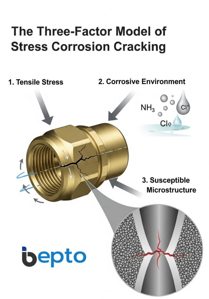
The Three-Factor Model
Stress corrosion cracking follows a well-established three-factor requirement:
Mechanical Stress Component:
- Residual stresses from manufacturing processes (machining, forming, welding)
- Applied stresses during installation (over-torquing, thermal expansion)
- Service stresses from vibration, pressure cycling, thermal cycling
- Stress concentration at design features (threads, keyways, sharp transitions)
Corrosive Environment:
- Ammonia and ammonium compounds (most aggressive for brass)
- Chloride ions from marine environments or industrial processes
- Sulfur-containing compounds (H2S, SO2, sulfates)
- Moisture acting as electrolyte for electrochemical reactions
Susceptible Material:
- High zinc content (>30%) creating galvanic couples
- Specific microstructures with zinc-rich phases
- Grain boundary precipitates acting as crack initiation sites
- Cold work increasing dislocation density and stored energy
Crack Initiation and Propagation
The cracking process follows predictable stages:
Initiation Phase:
- Preferential attack at high-stress locations
- Formation of micro-pits or surface roughening
- Concentration of stress at newly formed defects
- Transition from general corrosion to localized attack
Propagation Phase:
- Crack advances perpendicular to maximum tensile stress
- Transgranular path through zinc-rich areas
- Crack tip remains active while sides passivate
- Branching occurs at grain boundaries or phase interfaces
Final Failure:
- Reduced cross-sectional area increases stress intensity
- Accelerated crack growth rate
- Sudden fracture when critical crack size reached
- Characteristic brittle appearance with minimal plastic deformation
Critical Stress Thresholds
Research shows specific stress levels trigger SCC initiation:
Threshold Stress Values:
- CuZn30: 40-60% of yield strength3 in ammonia environments
- CuZn37: 60-80% of yield strength (improved resistance)
- CuZn39Pb3: 30-50% of yield strength (high susceptibility)
- Marine brass: 70-90% of yield strength (optimized composition)
These thresholds vary significantly with environmental severity and exposure time, emphasizing the importance of stress control in design and installation procedures.
Which Brass Alloys Offer Superior Crack Resistance?
Alloy composition dramatically influences stress corrosion cracking susceptibility, with specific compositions showing remarkable resistance improvements.
Marine-grade brass alloys (CuZn37, CuZn36Sn1) and aluminum brass (CuZn22Al2) offer superior crack resistance compared to standard brass (CuZn39Pb3) due to lower zinc content, beneficial alloying additions, and optimized microstructures that minimize galvanic effects and reduce environmental sensitivity while maintaining adequate mechanical properties for cable gland applications. Our alloy selection process prioritizes long-term reliability over initial cost considerations.
Comparative Alloy Performance
| Alloy Designation | Zinc Content | SCC Resistance | Marine Suitability | Cost Factor |
|---|---|---|---|---|
| CuZn39Pb3 (Standard) | 39% | Poor | Not Recommended | 1.0x |
| CuZn37 (Marine Brass) | 37% | Good | Excellent | 1.2x |
| CuZn36Sn1 | 36% | Very Good | Excellent | 1.4x |
| CuZn22Al2 (Al Brass) | 22% | Excellent | Outstanding | 1.6x |
| CuNi10Fe1Mn (Cupronickel) | 0% | Outstanding | Outstanding | 2.0x |
Metallurgical Factors Affecting Resistance
Zinc Content Impact:
- High zinc alloys (>35%) form zinc-rich β-phase
- β-phase acts as anodic sites promoting galvanic corrosion
- Lower zinc content (<35%) maintains single α-phase structure
- Homogeneous microstructure reduces electrochemical potential differences
Beneficial Alloying Elements:
- Tin (0.5-1.0%): Forms protective surface films, improves corrosion resistance
- Aluminum (1-2%): Creates adherent oxide layer, excellent marine performance
- Nickel (5-30%): Eliminates zinc completely, outstanding SCC resistance
- Iron (0.5-1.5%): Refines grain structure, improves mechanical properties
Microstructural Considerations:
- Single-phase α-brass shows superior resistance to two-phase structures
- Fine grain size reduces crack propagation rates
- Absence of lead improves environmental resistance
- Controlled cooling prevents harmful phase precipitation
Bepto’s Alloy Selection Strategy
At our facility, we’ve developed specific alloy recommendations based on application severity:
Standard Industrial Applications:
- CuZn37 marine brass for general-purpose cable glands
- Excellent balance of performance and cost-effectiveness
- Suitable for most industrial environments with proper installation
Harsh Marine Environments:
- CuZn36Sn1 for offshore platforms and coastal installations
- Superior resistance to chloride-induced cracking
- Proven track record in North Sea applications
Chemical Processing:
- CuZn22Al2 aluminum brass for aggressive chemical environments
- Outstanding resistance to ammonia and sulfur compounds
- Higher initial cost justified by extended service life
Critical Applications:
- CuNi10Fe1Mn cupronickel for ultimate reliability
- Zero zinc content eliminates dezincification risk
- Specified for nuclear, pharmaceutical, and safety-critical systems
How Do Manufacturing Processes Impact SCC Susceptibility?
Manufacturing processes significantly influence residual stress levels and microstructure, directly affecting stress corrosion cracking resistance.
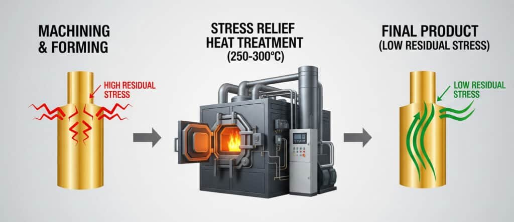
Manufacturing processes impact SCC susceptibility through residual stress introduction during machining, forming, and assembly operations, with cold working increasing stored energy and dislocation density, while proper stress relief heat treatment at 250-300°C can reduce residual stresses by 80-90% and optimize microstructure for maximum crack resistance. Our manufacturing protocols prioritize stress minimization throughout production.
Critical Manufacturing Stages
Machining Operations:
- Thread cutting introduces high surface stresses
- Tool geometry and cutting parameters affect residual stress
- Proper speeds, feeds, and cutting fluids minimize work hardening
- Final machining passes should be light to reduce surface stress
Forming Processes:
- Deep drawing creates circumferential and radial stresses
- Progressive forming reduces stress concentration compared to single-stage operations
- Intermediate annealing prevents excessive cold work accumulation
- Tool design minimizes sharp bends and stress concentrations
Assembly Procedures:
- Press-fitting components introduces assembly stresses
- Controlled interference fits prevent excessive stress levels
- Proper alignment prevents bending stresses during assembly
- Quality control ensures dimensional accuracy and fit
Stress Relief Heat Treatment
Thermal treatment represents the most effective method for reducing manufacturing stresses:
Treatment Parameters:
- Temperature: 250-300°C (below recrystallization temperature)
- Time: 1-2 hours depending on section thickness
- Atmosphere: Inert gas or reducing atmosphere to prevent oxidation
- Cooling: Slow cooling to room temperature prevents thermal stress
Microstructural Benefits:
- Reduces dislocation density and stored energy
- Relieves internal stresses without grain growth
- Improves ductility and toughness
- Maintains strength properties while improving SCC resistance
Quality Control:
- X-ray diffraction stress measurement4 before and after treatment
- Microhardness testing to verify stress relief effectiveness
- Metallographic examination for microstructural changes
- SCC testing on treated samples for validation
Surface Treatment Options
Surface modifications provide additional protection against crack initiation:
Shot Peening:
- Introduces beneficial compressive surface stresses
- Counteracts tensile stresses that promote cracking
- Improves fatigue resistance and surface finish
- Requires careful parameter control to avoid over-peening
Chemical Passivation:
- Creates protective surface films
- Reduces electrochemical activity
- Chromate treatments (where permitted) provide excellent protection
- Environmentally friendly alternatives include phosphate and silicate treatments
Protective Coatings:
- Nickel plating provides barrier protection
- Organic coatings for specific chemical environments
- Must ensure coating adhesion and durability
- Regular inspection and maintenance required
Roberto, a production manager at a German automotive supplier, experienced SCC failures in brass cable glands used in engine compartments. The combination of vibration, temperature cycling, and ammonia from urea-based emissions systems created ideal cracking conditions. After implementing our stress relief heat treatment protocol and switching to CuZn37 alloy, they achieved a 95% reduction in field failures and improved their warranty claims significantly.
What Environmental Factors Accelerate Cracking?
Environmental conditions play a crucial role in determining crack initiation time and propagation rates in brass cable glands.
Environmental factors that accelerate stress corrosion cracking include elevated temperatures (increasing reaction rates exponentially), chloride concentrations above 100 ppm, ammonia or ammonium compounds even at trace levels, pH extremes below 6 or above 9, and cyclic loading conditions that create fresh crack surfaces, with marine environments representing the most aggressive combination of multiple accelerating factors. Understanding these factors enables proper environmental assessment and mitigation strategies.
Temperature Effects
Temperature dramatically influences cracking kinetics:
Reaction Rate Acceleration:
- Arrhenius relationship5: 10°C increase doubles reaction rate
- Higher temperatures increase ion mobility and diffusion rates
- Thermal cycling creates additional mechanical stresses
- Elevated temperatures reduce material strength properties
Critical Temperature Ranges:
- Below 40°C: Very slow crack growth rates
- 40-80°C: Moderate acceleration, typical service range
- Above 80°C: Rapid crack propagation, high failure risk
- Thermal shock conditions create additional stress concentrations
Chemical Environment Severity
Different chemical species show varying aggressiveness:
Ammonia and Ammonium Compounds:
- Most aggressive environment for brass SCC
- Concentrations as low as 10 ppm can initiate cracking
- Forms stable complexes with copper ions
- Common in agricultural, refrigeration, and water treatment applications
Chloride Environments:
- Marine atmospheres with 0.1-10 mg/m² chloride deposition
- Industrial atmospheres with chloride contamination
- Threshold concentrations vary with temperature and humidity
- Synergistic effects with other aggressive species
Sulfur Compounds:
- H2S, SO2, and sulfate ions promote cracking
- Common in oil and gas processing environments
- Lower threshold concentrations than chlorides
- Create acidic conditions accelerating corrosion
Mechanical Loading Conditions
Dynamic loading significantly accelerates crack growth:
Cyclic Loading Effects:
- Fatigue loading creates fresh crack surfaces
- Removes protective films exposing active metal
- Stress concentration at crack tips increases local stress
- Frequency and amplitude affect crack growth rates
Vibration Environments:
- Continuous low-amplitude vibration
- Resonance conditions creating high dynamic stresses
- Equipment-induced vibration from pumps, compressors
- Transportation vibration in mobile applications
Installation Stresses:
- Over-torquing during installation
- Thermal expansion/contraction stresses
- Misalignment creating bending stresses
- Inadequate support causing additional loading
Which Prevention Strategies Deliver Long-Term Success?
Successful prevention requires a multi-faceted approach combining material selection, design optimization, manufacturing control, and environmental management.
Long-term prevention success requires implementing multiple strategies simultaneously: selecting crack-resistant alloys (CuZn37 or better), controlling manufacturing stresses through proper heat treatment, optimizing installation procedures to minimize applied stresses, implementing environmental protection measures, and establishing regular inspection protocols, with the most successful programs achieving 90% reduction in SCC failures through systematic application of these principles. Our comprehensive approach addresses all contributing factors.
Integrated Material Strategy
Primary Material Selection:
- Specify marine-grade brass (CuZn37) as minimum standard
- Use aluminum brass (CuZn22Al2) for severe environments
- Consider cupronickel for ultimate reliability requirements
- Avoid high-zinc alloys (>37% Zn) in corrosive environments
Secondary Protection Systems:
- Protective coatings where appropriate
- Cathodic protection in marine environments
- Environmental barriers and enclosures
- Chemical inhibitors in process systems
Manufacturing Excellence Program
Process Controls:
- Mandatory stress relief heat treatment for all brass components
- Controlled machining parameters to minimize work hardening
- Progressive forming techniques reducing peak stresses
- Quality assurance testing including residual stress measurement
Design Optimization:
- Eliminate sharp corners and stress concentrations
- Optimize thread profiles for stress distribution
- Provide adequate wall thickness for stress reduction
- Design for easy installation without over-stressing
Installation Best Practices
Torque Control:
- Specify maximum installation torques based on material properties
- Use calibrated torque tools for consistent application
- Train installation personnel on proper procedures
- Document installation parameters for quality records
Environmental Assessment:
- Evaluate service environment severity before specification
- Consider temperature, chemical exposure, and mechanical loading
- Implement environmental monitoring where appropriate
- Plan for changing environmental conditions over service life
Monitoring and Maintenance
Inspection Protocols:
- Regular visual inspection for crack initiation
- Non-destructive testing (dye penetrant, ultrasonic) for critical applications
- Environmental monitoring for aggressive species
- Performance tracking and failure analysis
Predictive Maintenance:
- Establish inspection intervals based on environmental severity
- Implement condition-based replacement strategies
- Track performance data for continuous improvement
- Update specifications based on field experience
Success Metrics and Validation
Our prevention strategies are validated through comprehensive performance tracking:
Field Performance Data:
- Standard brass glands: 18-month average life in marine environments
- Marine brass with stress relief: 8-year average life
- Aluminum brass in chemical service: 12-year average life
- Comprehensive prevention program: >95% success rate
Cost-Benefit Analysis:
- Prevention program cost: 15-25% premium over standard approach
- Failure cost avoidance: 300-500% return on investment
- Reduced maintenance costs: 60-80% reduction
- Improved system reliability: 99%+ availability achievement
Khalid, who manages a desalination plant in Saudi Arabia, initially experienced frequent brass gland failures due to the combination of high chloride levels, elevated temperatures, and vibration from high-pressure pumps. After implementing our comprehensive prevention program—including CuZn22Al2 alloy selection, stress relief treatment, controlled installation procedures, and quarterly inspection protocols—they’ve achieved over 4 years without a single SCC failure, saving over $200,000 in replacement costs and downtime.
Conclusion
Preventing stress corrosion cracking in brass cable glands requires a deep understanding of metallurgical principles combined with practical engineering solutions. Through our decade of experience and continuous research, we’ve proven that the right combination of alloy selection, manufacturing controls, and installation practices can virtually eliminate SCC failures. The key lies in recognizing that prevention costs far less than failure consequences. At Bepto, we’re committed to providing not just products, but complete solutions that ensure long-term reliability in the most demanding environments. When you choose our SCC-resistant brass cable glands, you’re investing in proven materials science and engineering excellence that delivers peace of mind for decades. 😉
FAQs About Brass Cable Gland Stress Corrosion Cracking
Q: What are the early signs of stress corrosion cracking in brass cable glands?
A: Early signs include fine hairline cracks perpendicular to stress direction, surface discoloration or tarnishing, and small pits or rough patches on the surface. These typically appear first at high-stress areas like threads, corners, or machining marks before propagating into the bulk material.
Q: How long does it take for stress corrosion cracking to cause failure?
A: Failure time varies from months to years depending on stress level, environment severity, and material composition. Standard brass in marine environments may fail within 6-18 months, while properly selected and treated materials can last 15-20 years under similar conditions.
Q: Can stress corrosion cracking be repaired once it starts?
A: SCC cannot be effectively repaired once initiated, as cracks continue propagating even after repair attempts. The only reliable solution is complete replacement with crack-resistant materials and proper installation procedures to prevent recurrence.
Q: Which is more important – alloy selection or stress relief treatment?
A: Both are critical and work synergistically, but alloy selection provides the foundation for SCC resistance. Marine-grade brass with stress relief treatment offers optimal performance, while standard brass will remain susceptible even with perfect stress relief.
Q: How much does SCC-resistant brass cost compared to standard brass?
A: Marine-grade brass typically costs 20-40% more than standard brass initially, but the total cost of ownership is significantly lower due to extended service life and reduced maintenance requirements, often providing 300-500% return on investment through failure prevention.
-
Learn about the electrochemical process where zinc is selectively leached from brass, weakening the material. ↩
-
Understand the difference between cracks that propagate through grains versus along grain boundaries in a material. ↩
-
Explore this fundamental mechanical property that defines the point at which a material begins to deform permanently. ↩
-
Discover the principles behind this advanced non-destructive technique for quantifying stress in crystalline materials. ↩
-
Learn about the fundamental formula in physical chemistry that describes the relationship between temperature and reaction rates. ↩
