

High-voltage installations pose serious risks to personnel, and inadequate cable gland insulation can turn routine maintenance into a life-threatening situation.
Insulated cable glands provide critical electrical isolation and arc flash1 protection in high-voltage applications, preventing dangerous electrical contact and reducing the risk of personnel injury during installation and maintenance operations.
Just last month, Hassan’s petrochemical facility avoided a potential fatality when their properly installed insulated cable glands contained an electrical fault that could have exposed maintenance workers to 15kV.
Table of Contents
- What Makes High-Voltage Cable Glands Different from Standard Glands?
- How Do Insulated Glands Protect Against Arc Flash and Electrical Contact?
- Which Insulation Materials and Ratings Are Required for Different Voltage Levels?
- What Safety Standards and Testing Requirements Apply to High-Voltage Glands?
What Makes High-Voltage Cable Glands Different from Standard Glands?
High-voltage applications demand specialized cable glands with enhanced safety features that go far beyond basic sealing.
High-voltage cable glands incorporate electrical insulation barriers, extended creepage distances2, tracking-resistant materials, and enhanced mechanical strength to prevent electrical flashover and protect personnel from dangerous voltage levels typically above 1kV.
Key Design Differences
Electrical Isolation Features:
- Insulation barriers: Physical separation between live conductors and metallic enclosure
- Extended creepage distances: Longer surface paths to prevent electrical tracking
- Corona shields: Reduce electrical stress concentrations
- Grounding provisions: Safe dissipation of fault currents
Material Requirements:
- Tracking resistance: CTI (Comparative Tracking Index) ratings of 400+ for high-voltage service
- Arc resistance: Materials that won’t carbonize under electrical stress
- Flame retardancy: UL94 V-0 rating minimum for safety compliance
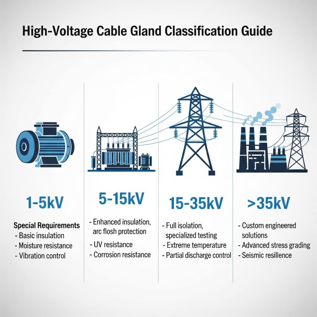
Voltage Classification Guide
| Voltage Range | Application Examples | Special Requirements |
|---|---|---|
| 1-5kV | Industrial motors, transformers | Basic insulation, IP protection |
| 5-15kV | Distribution systems, substations | Enhanced insulation, arc flash protection |
| 15-35kV | Transmission equipment | Full isolation, specialized testing |
| >35kV | High-voltage transmission | Custom engineered solutions |
I remember David’s concern when upgrading their facility to 11kV distribution. We provided cable glands with 15kV insulation rating and comprehensive arc flash protection – better to over-specify than risk personnel safety! 😉
How Do Insulated Glands Protect Against Arc Flash and Electrical Contact?
Arc flash incidents can cause severe burns and fatalities, making proper insulation design critical for personnel protection.
Insulated cable glands prevent arc flash by maintaining electrical isolation through specialized barrier systems, while extended insulation sleeves and non-conductive housings eliminate direct contact paths between personnel and energized conductors.
Arc Flash Protection Mechanisms
Primary Protection Barriers:
- Insulation sleeves: Cover exposed conductor portions during installation
- Barrier plates: Physical separation between cable entry and internal connections
- Non-conductive housings: Eliminate metallic contact paths
- Sealed interfaces: Prevent moisture ingress that could cause tracking
Secondary Protection Features:
- Pressure relief: Controlled venting in case of internal arc
- Flame barriers: Prevent fire propagation
- Mechanical reinforcement: Withstand arc blast forces
Real-World Protection Example
Hassan’s facility experienced a cable fault during a thunderstorm. The insulated cable glands we installed contained the electrical arc within the barrier system, preventing flashover to the enclosure. Without proper insulation, this could have energized the entire panel, creating a deadly hazard for the maintenance crew responding to the alarm.
Critical Safety Zones:
- Zone 1: Direct conductor contact (eliminated by insulation sleeves)
- Zone 2: Arc flash exposure area (minimized by barrier design)
- Zone 3: Step potential area (addressed by proper grounding)
Installation Safety Protocols
When working with insulated glands:
- Always verify de-energization before installation
- Use proper PPE rated for the voltage level
- Follow lockout/tagout procedures3
- Test insulation integrity after installation
- Document installation for maintenance records
Which Insulation Materials and Ratings Are Required for Different Voltage Levels?
Material selection directly impacts the safety and reliability of high-voltage cable gland installations.
Epoxy resin, cross-linked polyethylene (XLPE), and ceramic insulators provide the primary insulation, with material choice depending on voltage level, environmental conditions, and tracking resistance requirements ranging from 400V/mm for low voltage to 3kV/mm for transmission applications.
Insulation Material Comparison
Epoxy Resin Systems:
- Voltage range: Up to 35kV
- Advantages: Excellent tracking resistance, moldable, cost-effective
- Applications: Distribution panels, motor control centers
- CTI rating: 400-600 (excellent tracking resistance)
- Our recommendation: Cycloaliphatic epoxy for outdoor applications
Cross-Linked Polyethylene (XLPE):
- Voltage range: 1-25kV
- Advantages: Flexible, chemical resistant, self-extinguishing
- Applications: Cable terminations, flexible connections
- Temperature rating: -40°C to +90°C continuous operation
- Special feature: Excellent moisture resistance
Ceramic Insulators:
- Voltage range: 15kV and above
- Advantages: Superior tracking resistance, high temperature capability
- Applications: Substation equipment, transmission lines
- Limitations: Brittle, requires careful handling
- Best for: Extreme environmental conditions
Voltage-Specific Requirements
1-5kV Applications:
- Minimum insulation thickness: 2-3mm
- CTI rating: 400 minimum
- Flame rating: UL94 V-1 or better
- Common materials: Modified nylon, epoxy
5-15kV Applications:
- Minimum insulation thickness: 5-8mm
- CTI rating: 500+ required
- Enhanced creepage distances: 8-12mm per kV
- Preferred materials: Epoxy resin, XLPE
15kV+ Applications:
- Custom engineered solutions
- Multiple barrier systems
- Specialized testing requirements
- Materials: High-grade ceramics, specialized polymers
Environmental Considerations
Outdoor Applications:
- UV-resistant materials essential
- Hydrophobic surface treatments
- Enhanced tracking resistance
- Temperature cycling capability
Indoor Controlled Environments:
- Standard insulation materials acceptable
- Focus on arc resistance
- Flame retardancy critical
- Chemical compatibility important
What Safety Standards and Testing Requirements Apply to High-Voltage Glands?
Compliance with safety standards ensures your insulated cable glands provide reliable personnel protection.
High-voltage cable glands must meet IEC 624444, IEEE 386, and UL standards for insulation coordination, with mandatory testing including dielectric strength, tracking resistance, arc resistance, and mechanical strength verification at specified voltage levels.
Key Safety Standards
International Standards:
- IEC 62444: Cable glands for electrical installations
- IEC 60529: IP protection ratings
- IEC 60112: Comparative tracking index testing
- IEC 61984: Connectors for high-voltage applications
North American Standards:
- IEEE 386: Separable insulated connector systems
- UL 514B: Fittings for conduit and outlet boxes
- NEMA CC 1: Electric power connection for substations
- ANSI C119.4: High-voltage connections
Required Testing Protocols
Electrical Tests:
- Dielectric strength: 2.5x rated voltage for 1 minute
- Impulse withstand: Lightning and switching surge tests
- Partial discharge5: <10pC at 1.1x rated voltage
- Tracking resistance: CTI testing per IEC 60112
Mechanical Tests:
- Pull-out strength: Minimum 500N for most applications
- Vibration resistance: IEC 60068-2-6 compliance
- Impact resistance: IEC 62262 mechanical protection
- Temperature cycling: -40°C to +85°C minimum range
Environmental Tests:
- Salt spray: 96-hour exposure per IEC 60068-2-11
- UV exposure: 1000 hours minimum
- Thermal aging: Accelerated aging at elevated temperatures
- Chemical resistance: Specific to application environment
Certification Requirements
Third-Party Testing:
We ensure all our high-voltage cable glands undergo rigorous third-party testing at accredited laboratories. This includes:
- TUV certification for European markets
- UL listing for North American applications
- CSA approval for Canadian installations
- ATEX certification for explosive atmospheres
Quality Documentation:
- Individual test certificates for each batch
- Material traceability records
- Installation and maintenance manuals
- Compliance declarations
Installation Verification
Field Testing Requirements:
After installation, verify:
- Insulation resistance: Minimum 1000MΩ at test voltage
- Continuity testing: Grounding path integrity
- Torque verification: Proper mechanical assembly
- Visual inspection: No damage or contamination
David’s team now performs routine insulation testing every six months, catching potential issues before they become safety hazards. This proactive approach has eliminated unplanned outages and safety incidents.
Conclusion
Proper selection and installation of insulated cable glands is essential for preventing electrical accidents and ensuring personnel safety in high-voltage environments.
FAQs About High-Voltage Insulated Cable Glands
Q: What voltage level requires insulated cable glands instead of standard metal glands?
A: Generally, applications above 1kV require insulated cable glands for personnel safety. However, even lower voltages may need insulation in wet or conductive environments. We recommend insulated glands for any application where personnel could contact energized parts during maintenance.
Q: How often should high-voltage cable glands be inspected and tested?
A: Annual visual inspections are minimum, with electrical testing every 2-3 years or after any electrical fault. Critical applications may require more frequent testing. We provide detailed maintenance schedules based on your specific voltage levels and environmental conditions.
Q: Can insulated cable glands be repaired if damaged, or must they be replaced?
A: High-voltage insulated glands should never be repaired – they must be replaced if damaged. Any compromise to the insulation system creates a serious safety hazard. The cost of replacement is minimal compared to the risk of personnel injury or equipment damage.
Q: What’s the difference between touch-safe and dead-front cable gland designs?
A: Touch-safe designs prevent accidental contact with live parts during normal operation, while dead-front designs eliminate all exposed energized components. Dead-front is preferred for high-voltage applications as it provides maximum personnel protection during maintenance activities.
Q: Do insulated cable glands require special installation tools or procedures?
A: Yes, high-voltage installations require specialized tools, proper PPE, and trained personnel. Installation must follow manufacturer procedures and electrical codes. We provide comprehensive installation training and support to ensure safe, compliant installations.
-
Learn from OSHA about the dangers of arc flash and the safety measures required to prevent it. ↩
-
Understand this critical design principle for preventing electrical tracking along insulator surfaces. ↩
-
Review the official OSHA standard for controlling hazardous energy during equipment service and maintenance. ↩
-
Explore the international standard that specifies the requirements for cable glands in electrical installations. ↩
-
Discover how this non-destructive test detects insulation defects before they lead to catastrophic failure. ↩
