A single cable gland failure can compromise an entire SIL-rated safety system. Understanding how mechanical components affect functional safety is critical for preventing industrial disasters.
Cable glands impact functional safety through their failure modes, environmental protection capabilities, and systematic capability levels, requiring proper SIL assessment, failure rate data analysis, and integration into overall safety instrumented system design to maintain required safety integrity levels.
Last month, Hassan called me urgently from his petrochemical plant. Their SIL 2 emergency shutdown system had failed during testing because water ingress through a compromised cable gland caused sensor malfunction. This incident reminded me why mechanical components deserve equal attention in functional safety design.
Table of Contents
- What Is Functional Safety and How Do Mechanical Components Fit In?
- How Do Cable Glands Affect Safety Instrumented System Performance?
- What Are the SIL Requirements for Cable Glands in Safety Applications?
- How Do You Select and Specify Cable Glands for SIL-Rated Systems?
What Is Functional Safety and How Do Mechanical Components Fit In?
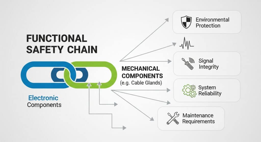
Functional safety1 focuses on preventing hazardous failures in safety-critical systems. While attention often centers on electronic components, mechanical parts like cable glands play equally crucial roles.
Functional safety requires all components in the safety chain to meet specified integrity levels, including mechanical components that provide environmental protection, signal integrity, and system reliability through their failure modes, maintenance requirements, and systematic capability assessments.
Understanding Safety Integrity Levels (SIL)
SIL Definitions and Requirements:
| SIL Level | Risk Reduction Factor | Probability of Failure on Demand (PFD) | Application Examples |
|---|---|---|---|
| SIL 1 | 10 to 100 | 10⁻¹ to 10⁻² | Non-critical process shutdowns |
| SIL 2 | 100 to 1,000 | 10⁻² to 10⁻³ | Emergency shutdown systems |
| SIL 3 | 1,000 to 10,000 | 10⁻³ to 10⁻⁴ | Fire and gas detection systems |
| SIL 4 | 10,000 to 100,000 | 10⁻⁴ to 10⁻⁵ | Nuclear reactor protection |
Note: Safety Integrity Levels (SIL)2 quantify the target level of risk reduction provided by a safety function. The Probability of Failure on Demand (PFD)3 is a key metric for systems operating in low-demand mode.
The Role of Mechanical Components
Critical Functions in Safety Systems:
- Environmental protection: Preventing ingress that could cause dangerous failures
- Signal integrity: Maintaining electrical continuity and isolation
- Mechanical reliability: Ensuring connections remain secure under stress
- Systematic capability: Supporting overall system architecture requirements
David recently shared: “Chuck, we never realized how much our cable gland selection affected our SIL calculations until we did a proper analysis. The impact was significant.”
IEC 61508 Framework for Mechanical Components
Lifecycle Requirements:
- Concept phase: Hazard analysis including mechanical failure modes
- Design phase: Systematic capability assessment for mechanical parts
- Implementation: Proper installation and configuration procedures
- Operation: Maintenance and testing protocols
- Decommissioning: Safe removal and disposal procedures
The IEC 615084 standard provides a comprehensive framework for managing functional safety throughout the entire lifecycle of a system.
Systematic Capability Levels:
- SC 1: Basic design practices and documentation
- SC 2: Enhanced quality management and verification
- SC 3: Formal development processes and independent assessment
- SC 4: Highest level with comprehensive lifecycle management
How Do Cable Glands Affect Safety Instrumented System Performance?
Cable glands influence SIS performance through multiple failure mechanisms that can compromise safety functions. Understanding these impacts is essential for proper system design.
Cable glands affect SIS performance through dangerous undetected failures (water ingress causing sensor drift), dangerous detected failures (complete seal failure), safe failures (obvious leakage), and systematic failures (improper installation or specification), each requiring different mitigation strategies.
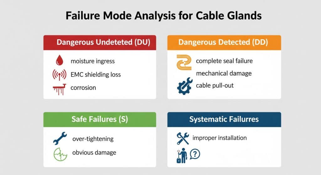
Failure Mode Analysis for Cable Glands
Dangerous Undetected Failures (DU):
- Gradual seal degradation allowing moisture ingress
- Partial loss of EMC shielding causing interference
- Slow corrosion of internal components
- Micro-movements causing intermittent connections
Dangerous Detected Failures (DD):
- Complete seal failure with obvious leakage
- Mechanical damage preventing proper sealing
- Visible corrosion or deterioration
- Cable pull-out or displacement
Safe Failures (S):
- Over-tightening causing obvious damage
- Complete loss of environmental rating
- Mechanical failure preventing installation
- Clear indication of compromise
Impact on Safety Function Performance
Signal Integrity Effects:
- Water ingress can cause sensor measurement drift
- Corrosion increases contact resistance
- EMC degradation allows interference
- Temperature cycling affects calibration
Hassan told me: “We discovered that moisture ingress through cable glands was causing our pressure transmitters to drift by 2%, which was enough to prevent proper trip function.”
Quantitative Impact Assessment
Failure Rate Contributions:
- Cable gland failure rates: 10⁻⁶ to 10⁻⁴ failures per hour
- Environmental factors: 2x to 10x multiplier
- Installation quality: 1.5x to 5x multiplier
- Maintenance effectiveness: 0.5x to 2x multiplier
PFD Calculation Example:
For a SIL 2 pressure safety valve system:
- Sensor PFD: 1×10⁻³
- Logic solver PFD: 5×10⁻⁴
- Final element PFD: 2×10⁻³
- Cable gland contribution: 1×10⁻⁴
- Total system PFD: 3.6×10⁻³ (still within SIL 2 range)
Common Cause Failures
Environmental Stress Factors:
- Temperature cycling affecting multiple glands
- Chemical exposure causing systematic degradation
- Vibration loosening connections across the system
- UV radiation degrading sealing materials
Mitigation Strategies:
- Diversified cable gland types and materials
- Redundant sealing methods
- Regular inspection and maintenance programs
- Environmental protection measures
At Bepto, we provide detailed failure mode analysis and reliability data for all our cable glands to support your SIL calculations. Our engineering team can help optimize your safety system design. 😉
What Are the SIL Requirements for Cable Glands in Safety Applications?
Cable glands used in SIL-rated systems must meet specific requirements for systematic capability, failure rates, and documentation. These requirements vary by SIL level and application.
SIL requirements for cable glands include systematic capability certification (SC 2 minimum for SIL 2 applications), documented failure rate data, proof test procedures, maintenance intervals, and integration into overall safety lifecycle management processes.
Systematic Capability Requirements
SC 2 Requirements (Minimum for SIL 2):
- Quality management system (ISO 9001 or equivalent)
- Configuration management procedures
- Verification and validation processes
- Documentation and traceability systems
- Competence management for personnel
SC 3 Requirements (Recommended for SIL 3):
- Formal development lifecycle
- Independent verification activities
- Advanced quality assurance measures
- Comprehensive testing protocols
- Third-party assessment and certification
Documentation Requirements
Essential Documentation Package:
- Safety manual with failure mode analysis
- Installation and maintenance procedures
- Proof test instructions and intervals
- Environmental limitations and derating factors
- Systematic capability certificate
Failure Rate Data Requirements:
- Lambda (λ) values for different failure modes
- Environmental stress factors
- Confidence intervals and data sources
- Mission time and wear-out considerations
- Common cause failure analysis
David shared: “Having proper SIL documentation from Bepto made our TÜV assessment much smoother. The assessor was impressed with the completeness of the safety case.”
Proof Testing Requirements
Proof Test Objectives:
- Detect dangerous undetected failures
- Verify continued safety function capability
- Restore system to known safe state
- Update failure rate data based on experience
Cable Gland Proof Test Procedures:
- Visual inspection for damage or deterioration
- Torque verification within specified ranges
- Insulation resistance testing
- Pressure testing for sealed applications
- Continuity verification for EMC applications
Integration with Safety Lifecycle
Design Phase Integration:
- Include cable glands in HAZOP studies5
- Consider failure modes in FMEA analysis
- Specify systematic capability requirements
- Define proof test strategies
Operation Phase Requirements:
- Regular inspection schedules
- Preventive maintenance programs
- Incident reporting and analysis
- Performance monitoring and trending
Hassan recently told me: “Integrating cable gland requirements into our safety lifecycle management system helped us identify potential issues before they became problems.”
How Do You Select and Specify Cable Glands for SIL-Rated Systems?
Proper selection and specification of cable glands for SIL applications requires systematic evaluation of safety requirements, environmental conditions, and lifecycle considerations.
Cable gland selection for SIL systems requires evaluation of systematic capability level, failure rate data compatibility with safety targets, environmental suitability, proof test feasibility, and long-term availability to support system lifecycle requirements.
Selection Criteria Matrix
Safety Requirements:
- Required SIL level and systematic capability
- Failure rate targets and allocation
- Proof test interval compatibility
- Common cause failure considerations
- Maintenance accessibility requirements
Technical Specifications:
- Cable types and size ranges
- Environmental protection ratings (IP, NEMA)
- Material compatibility with process fluids
- Temperature and pressure ratings
- EMC and grounding requirements
Lifecycle Considerations:
- Expected service life (typically 20+ years)
- Spare parts availability
- Supplier stability and support
- Obsolescence management
- Upgrade and modification flexibility
Specification Development Process
Step 1: Safety Requirement Analysis
- Review SIS design and safety requirements specification
- Identify cable gland locations and functions
- Determine failure rate allocations
- Specify systematic capability requirements
Step 2: Environmental Assessment
- Analyze installation environment conditions
- Consider chemical compatibility requirements
- Evaluate mechanical stress factors
- Assess maintenance accessibility
Step 3: Technical Specification
- Define performance requirements
- Specify testing and certification needs
- Establish quality and documentation requirements
- Include lifecycle support provisions
Supplier Evaluation Criteria
Technical Capability:
- SIL certification and systematic capability
- Failure rate data quality and sources
- Testing and validation capabilities
- Technical support and engineering resources
Quality System:
- ISO 9001 certification minimum
- Configuration management processes
- Change control procedures
- Traceability and documentation systems
Business Considerations:
- Financial stability and longevity
- Global support capabilities
- Spare parts availability
- Technology roadmap alignment
David told me: “Using your systematic selection process helped us choose cable glands that not only met our current SIL requirements but also provided flexibility for future modifications.”
Bepto’s SIL Support Services
We understand the complexity of SIL applications and provide comprehensive support:
- SIL certification for systematic capability levels
- Detailed failure rate data with confidence intervals
- Safety manual development for your specific applications
- Technical training on SIL requirements and implementation
- Lifecycle support including obsolescence management
Common Specification Mistakes
Technical Errors:
- Under-specifying systematic capability requirements
- Ignoring environmental stress factors
- Inadequate proof test procedures
- Missing common cause failure analysis
Commercial Mistakes:
- Focusing only on initial cost
- Ignoring lifecycle support requirements
- Inadequate supplier qualification
- Missing spare parts strategy
Documentation Issues:
- Incomplete safety case development
- Missing failure mode analysis
- Inadequate maintenance procedures
- Poor change control processes
Hassan shared: “The investment in proper SIL-qualified cable glands paid for itself when we avoided a major safety system failure that could have shut down our entire plant.”
Conclusion
Cable glands play a critical role in functional safety systems, requiring proper SIL assessment, systematic capability certification, and lifecycle management to maintain safety integrity levels.
FAQs About SIL and Cable Glands
Q: Do all cable glands in a SIL system need to be SIL-certified?
A: Not necessarily. Only cable glands that can cause dangerous failures of safety functions need SIL assessment. However, it’s often simpler to use SIL-qualified products throughout the safety system to ensure consistency and simplify documentation.
Q: How do I calculate the impact of cable gland failures on my overall SIL rating?
A: Include cable gland failure rates in your PFD calculations using the same methods as other components. Consider both random hardware failures and systematic failures. At Bepto, we provide detailed calculation guidance and failure rate data to support your analysis.
Q: What’s the difference between SC 2 and SC 3 cable glands?
A: SC 3 requires more rigorous development processes, independent verification, and formal lifecycle management. SC 2 is sufficient for most SIL 2 applications, while SC 3 is recommended for SIL 3 and required for SIL 4 applications.
Q: How often should cable glands be proof tested in SIL applications?
A: Proof test intervals depend on the required PFD and cable gland failure rates. Typical intervals range from 1-5 years. The key is balancing safety requirements with practical maintenance considerations.
Q: Can I use standard industrial cable glands in SIL applications?
A: Standard cable glands may be suitable if they meet the systematic capability requirements and you have adequate failure rate data. However, purpose-designed SIL products often provide better documentation and lifecycle support for safety applications.
-
Learn the official definition and core principles of functional safety from an international standards authority. ↩
-
Get a detailed breakdown of the different Safety Integrity Levels (SIL) and their risk reduction requirements. ↩
-
Understand how Probability of Failure on Demand (PFD) is calculated and used to determine SIL ratings. ↩
-
Access an overview of the IEC 61508 international standard for functional safety. ↩
-
Explore the structured methodology of a Hazard and Operability (HAZOP) study for identifying potential system risks. ↩