

Introduction
Think all cable glands provide the same sealing and retention performance? One loose cable or failed seal can lead to water ingress, system failure, and thousands of dollars in downtime. The sealing range and cable retention capabilities vary dramatically between different gland types, materials, and designs, making proper selection critical for reliable electrical installations.
Cable gland sealing ranges typically vary from 2-4mm for standard designs to 8-12mm for wide-range models, while cable retention forces can range from 200N for basic nylon glands to over 2000N for heavy-duty metal designs, with performance directly impacting system reliability, maintenance requirements, and long-term operational costs. Understanding these differences is essential for matching gland specifications to specific cable types and installation requirements.
Last month, Marcus, an electrical contractor in Manchester, contacted us after experiencing repeated seal failures in an outdoor substation installation. The standard cable glands he initially selected had insufficient sealing range for the cable variations on site, leading to water ingress and equipment damage during the first heavy rainfall. This kind of sealing failure can cascade through entire electrical systems, which is why we’ve developed comprehensive testing protocols and selection guides for all our cable gland sealing and retention systems.
Table of Contents
- What Determines Cable Gland Sealing Range Performance?
- How Do Different Gland Types Compare for Cable Retention Strength?
- What Factors Affect Long-Term Sealing Reliability?
- How Do You Match Gland Specifications to Cable Requirements?
- What Are the Testing Standards for Sealing and Retention Performance?
- Conclusion
- FAQs About Cable Gland Sealing and Retention
What Determines Cable Gland Sealing Range Performance?
Cable gland sealing range performance is determined by seal design geometry, elastomer material properties, compression mechanism efficiency, and manufacturing tolerances, with these factors collectively defining the minimum and maximum cable diameters that can achieve reliable IP67/IP681 sealing under specified test conditions.
The science behind effective sealing involves understanding how elastomeric seals deform under compression and how this deformation creates a watertight barrier around cables of varying diameters.
Seal Design Fundamentals
O-Ring vs. Membrane Seals:
Different seal types offer varying performance characteristics:
- O-ring seals: Precise sealing for narrow diameter ranges (typically 2-3mm)
- Membrane seals: Flexible design accommodating wider ranges (up to 8-10mm)
- Multi-lip seals: Enhanced sealing with redundant barriers
- Conical seals: Self-centering design for consistent performance
Compression Mechanics:
Effective sealing requires optimal compression ratios:
- Under-compression: Insufficient seal contact pressure
- Over-compression: Seal extrusion and premature failure
- Optimal range: 15-25% compression for most elastomers
- Progressive compression: Gradual increase maintains seal integrity
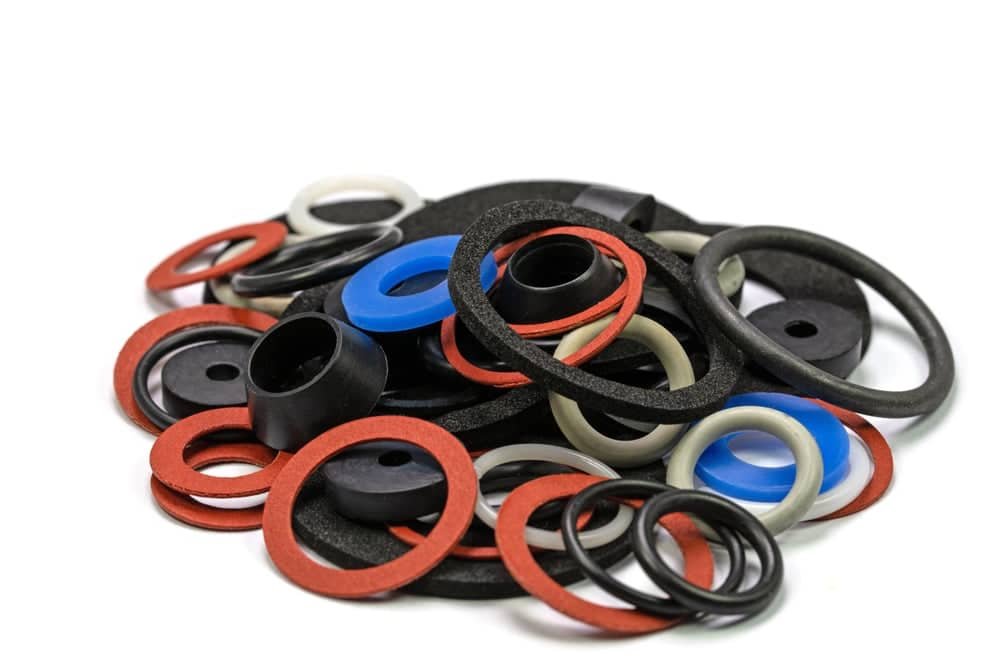
Material Properties Impact
Elastomer Selection:
Different rubber compounds affect sealing performance:
- Nitrile (NBR): Good general purpose, temperature range -40°C to +100°C
- EPDM: Excellent weather resistance, -50°C to +150°C
- Viton (FKM): Chemical resistance, -20°C to +200°C
- Silicone: Wide temperature range, -60°C to +200°C
Shore Hardness2 Effects:
Durometer affects sealing characteristics:
- 60-70 Shore A: Maximum flexibility, wider sealing range
- 70-80 Shore A: Balanced performance for most applications
- 80-90 Shore A: Higher retention force, narrower sealing range
- Custom formulations: Optimized for specific requirements
Geometric Design Factors
Seal Groove Dimensions:
Precise machining ensures consistent performance:
- Groove width: Typically 1.2-1.5x seal cross-section
- Groove depth: Controls compression ratio
- Surface finish: Ra 0.8-1.6μm for optimal seal contact
- Corner radii: Prevent seal damage during assembly
Cable Entry Geometry:
Entry design affects sealing effectiveness:
- Straight-through: Simple design, moderate sealing range
- Tapered entry: Self-centering, improved cable guidance
- Step design: Multiple sealing diameters in one gland
- Adjustable geometry: Field-customizable sealing range
Manufacturing Tolerance Impact
Critical Dimensions:
Tight tolerances ensure consistent sealing:
- Thread pitch accuracy: ±0.05mm for proper compression
- Seal groove dimensions: ±0.1mm tolerance typical
- Surface concentricity: <0.05mm runout
- Material consistency: Batch-to-batch variation control
Marcus discovered that his sealing failures weren’t just due to wrong size selection, but also poor manufacturing quality in the original glands. The seal grooves had excessive runout, preventing uniform compression around the cable circumference. Our precision CNC machining ensures consistent geometry that delivers reliable sealing across the full specified range.
How Do Different Gland Types Compare for Cable Retention Strength?
Different cable gland types exhibit significantly varying retention capabilities, with basic nylon glands providing 200-500N retention force, enhanced designs offering 800-1200N, metal glands delivering 1500-2500N, and specialized high-retention systems achieving over 3000N, depending on design features, materials, and cable interaction mechanisms.
Retention Mechanism Types
Compression-Based Retention:
Standard approach using seal compression:
- Relies on friction between seal and cable jacket
- Retention force proportional to compression force
- Typical performance: 200-800N depending on design
- Suitable for most general applications
Mechanical Gripping Systems:
Enhanced retention through mechanical features:
- Internal teeth or ridges grip cable jacket
- Progressive engagement under load
- Retention forces: 800-2000N typical
- Ideal for high-stress applications
Armor Wire Clamping:
Specialized designs for armored cables:
- Direct clamping of steel armor wires
- Exceptional retention strength: 2000-5000N
- Prevents armor wire pullback
- Critical for industrial and marine applications
Material Impact on Retention
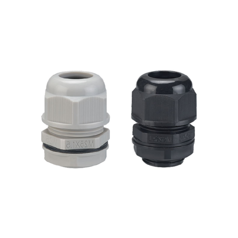
Nylon Cable Glands:
Cost-effective with moderate retention:
- Standard grades: 200-400N retention
- Glass-filled grades: 400-800N retention
- Enhanced designs: Up to 1200N possible
- Temperature affects performance significantly
Brass and Bronze Glands:
Superior mechanical properties:
- Consistent retention across temperature range
- Typical performance: 1000-2000N
- Excellent for outdoor applications
- Corrosion resistance varies by alloy
Stainless Steel Glands:
Maximum retention capability:
- 316L stainless: 1500-2500N typical
- Duplex stainless: Up to 3000N possible
- Excellent corrosion resistance
- Suitable for harsh chemical environments
Design Features Affecting Retention
Thread Pitch and Engagement:
Mechanical advantage affects retention:
- Fine threads: Higher compression force, better retention
- Coarse threads: Faster assembly, moderate retention
- Thread engagement length: Minimum 1.5x diameter
- Thread quality: Precision machining essential
Internal Geometry:
Design details impact performance:
- Taper angles: Optimize compression distribution
- Surface textures: Enhance grip on cable jacket
- Multiple compression zones: Distribute stress
- Progressive engagement: Prevent damage during assembly
Cable Type Compatibility
Flexible Cables:
Require careful retention design:
- PVC jackets: Good grip characteristics
- Polyurethane jackets: Excellent retention
- Rubber jackets: Variable performance
- Smooth jackets: May require enhanced designs
Armored Cables:
Specialized retention requirements:
- Steel wire armor3: Requires armor clamping
- Steel tape armor: Different retention mechanism
- Aluminum armor: Lower strength considerations
- Braided armor: Requires specific gland designs
Performance Testing Results
Based on our comprehensive testing program:
| Gland Type | Material | Typical Retention (N) | Maximum Retention (N) |
|---|---|---|---|
| Standard Nylon | PA66 | 300-500 | 800 |
| Enhanced Nylon | PA66 + GF | 500-800 | 1200 |
| Brass | CW617N | 800-1500 | 2000 |
| Stainless Steel | 316L | 1200-2000 | 2500 |
| Armor Clamp | Various | 2000-3000 | 5000+ |
Hassan, who manages several petrochemical facilities in Kuwait, learned the importance of proper retention specification when vibration from rotating equipment caused cable pullout failures in his original installation. We worked together to specify high-retention stainless steel glands with mechanical gripping features, eliminating the pullout issues and providing long-term reliability in his demanding environment.
What Factors Affect Long-Term Sealing Reliability?
Long-term sealing reliability is affected by temperature cycling causing seal degradation, UV exposure leading to elastomer hardening, chemical exposure causing swelling or deterioration, mechanical stress from vibration and movement, and aging-related changes in material properties, with properly selected systems maintaining IP67/IP68 performance for 15-20 years under normal conditions.
Temperature Effects on Sealing
Thermal Cycling Impact:
Repeated temperature changes stress sealing systems:
- Differential expansion between materials
- Seal compression loss at high temperatures
- Brittleness at low temperatures
- Accelerated aging from thermal stress
Material Selection for Temperature:
Different elastomers for different ranges:
- Standard applications (-20°C to +80°C): NBR or EPDM
- High temperature (+80°C to +150°C): EPDM or Viton
- Extreme temperature (>+150°C): Specialized compounds
- Low temperature (<-40°C): Silicone or special NBR
Environmental Degradation Factors
UV Radiation Effects:
Sunlight degrades many seal materials:
- Ozone formation accelerates degradation
- Surface cracking reduces sealing effectiveness
- Color changes indicate material breakdown
- Carbon black provides UV protection
Chemical Exposure:
Industrial environments challenge sealing materials:
- Acids: Cause hydrolysis in susceptible elastomers
- Bases: Attack ester linkages in some compounds
- Solvents: Cause swelling and property changes
- Oils: Can improve or degrade performance depending on type
Mechanical Stress Factors
Vibration and Movement:
Dynamic loads affect seal performance:
- Fretting wear at seal interfaces
- Fatigue cracking from cyclic stress
- Seal extrusion under dynamic loads
- Cable movement within gland
Installation Stress:
Improper installation affects longevity:
- Over-tightening causes seal extrusion
- Under-tightening allows seal relaxation
- Misalignment creates uneven stress
- Contamination during assembly
Aging and Time Effects
Elastomer Aging Mechanisms:
All rubber compounds age over time:
- Cross-link density changes
- Plasticizer migration
- Oxidation reactions
- Compression set4 development
Predictive Testing:
We use accelerated aging to predict performance:
- Thermal aging per ASTM D573
- Ozone resistance per ASTM D1149
- Compression set per ASTM D395
- Chemical immersion testing
Maintenance and Inspection
Visual Inspection Criteria:
Regular inspection identifies potential issues:
- Surface cracking or checking
- Color changes indicating degradation
- Hardness changes (durometer testing)
- Compression set measurement
Replacement Indicators:
Know when to replace sealing systems:
- Visible seal damage or extrusion
- Loss of sealing performance (pressure testing)
- Hardness increase >20% from original
- Chemical attack evidence
Design for Longevity
Seal Protection Features:
Design elements that extend seal life:
- UV-resistant materials for outdoor use
- Chemical-resistant compounds for harsh environments
- Backup seals for critical applications
- Replaceable seal designs for maintenance
Quality Assurance:
Manufacturing controls ensure longevity:
- Material traceability and certification
- Cure monitoring for consistent properties
- Dimensional inspection for proper fit
- Batch testing for performance verification
Marcus’s Manchester installation now includes a proactive maintenance program based on our recommendations. Regular visual inspections every 6 months and durometer testing annually help identify seals approaching replacement before failure occurs, preventing the costly water ingress issues he experienced initially.
How Do You Match Gland Specifications to Cable Requirements?
Matching gland specifications to cable requirements involves analyzing cable outer diameter ranges, jacket material compatibility, environmental conditions, mechanical stress requirements, and electrical specifications, with proper selection ensuring optimal sealing performance, adequate retention strength, and long-term reliability for specific installation conditions.
Cable Parameter Analysis
Diameter Measurement:
Accurate cable sizing is fundamental:
- Measure at multiple points along cable length
- Account for manufacturing tolerances (typically ±5%)
- Consider cable deformation under installation stress
- Include any protective coverings or conduits
Jacket Material Identification:
Different materials require different approaches:
- PVC: Good general compatibility, moderate retention
- Polyurethane: Excellent retention, chemical resistance
- Polyethylene: Low friction, may require enhanced retention
- Rubber compounds: Variable properties, check compatibility
Cable Construction Considerations:
Internal construction affects gland selection:
- Solid conductors: Rigid, predictable diameter
- Stranded conductors: More flexible, variable diameter
- Shielded cables: May require EMC glands
- Armored cables: Need specialized retention systems
Environmental Matching
IP Rating Requirements:
Select appropriate protection level:
- IP54: Dust protection, splash water resistance
- IP65: Dust-tight, water jet protection
- IP67: Dust-tight, temporary immersion protection
- IP68: Dust-tight, continuous immersion protection
Temperature Range Matching:
Ensure materials suit operating conditions:
- Ambient temperature extremes
- Self-heating from electrical load
- Solar heating effects (outdoor installations)
- Process temperature exposure (industrial applications)
Chemical Compatibility:
Match materials to exposure conditions:
- Cleaning chemicals and solvents
- Process chemicals in industrial facilities
- Atmospheric pollutants in urban areas
- Marine environments with salt spray
Mechanical Requirements
Retention Force Calculation:
Determine required retention strength:
- Cable weight and vertical installation loads
- Vibration and dynamic forces
- Thermal expansion/contraction stress
- Safety factors for critical applications
Stress Analysis:
Consider all mechanical loads:
- Installation pulling forces
- Service loop requirements
- Conduit or tray movement
- Equipment vibration transmission
Application-Specific Selection
Indoor Applications:
Typically less demanding requirements:
- Standard temperature ranges
- Minimal UV exposure
- Controlled chemical environment
- Lower mechanical stress
Outdoor Applications:
Enhanced specifications required:
- UV-resistant materials
- Wide temperature ranges
- Weather sealing requirements
- Enhanced mechanical properties
Industrial Applications:
Demanding performance requirements:
- Chemical resistance
- High temperature capability
- Vibration resistance
- Enhanced retention strength
Selection Process Framework
Step 1: Cable Analysis
- Measure cable diameter range
- Identify jacket material
- Determine construction type
- Note any special features
Step 2: Environmental Assessment
- Define operating temperature range
- Identify chemical exposures
- Determine IP rating requirements
- Assess UV exposure levels
Step 3: Mechanical Requirements
- Calculate retention force needs
- Assess vibration levels
- Determine installation stresses
- Define safety factors
Step 4: Gland Selection
- Match sealing range to cable diameter
- Select appropriate materials
- Verify retention capability
- Confirm environmental compatibility
Common Selection Mistakes
Undersized Sealing Range:
Consequences of poor sizing:
- Inadequate sealing performance
- Excessive compression stress
- Premature seal failure
- Water ingress risk
Material Incompatibility:
Chemical compatibility issues:
- Seal swelling or degradation
- Reduced sealing effectiveness
- Shortened service life
- Unexpected failure modes
Insufficient Retention:
Inadequate retention specification:
- Cable pullout under stress
- Conductor damage
- System failure
- Safety hazards
Quality Verification
Installation Testing:
Verify proper selection through testing:
- Pressure testing for sealing verification
- Pull testing for retention confirmation
- Visual inspection for proper fit
- Documentation of test results
Hassan’s facilities now use our comprehensive selection matrix that considers all these factors systematically. This structured approach has eliminated the trial-and-error selection process he previously used, resulting in first-time-right specifications and zero sealing failures over the past two years of installations.
What Are the Testing Standards for Sealing and Retention Performance?
Testing standards for cable gland sealing and retention performance include IEC 624445 for general cable gland requirements, IP testing per IEC 60529, retention testing per manufacturer specifications, temperature cycling per IEC 60068, and chemical resistance testing per relevant ASTM standards, with comprehensive testing ensuring reliable performance across specified operating conditions.
International Testing Standards
IEC 62444 – Cable Glands for Electrical Installations:
The primary international standard covering:
- Mechanical strength requirements
- Sealing performance criteria
- Temperature testing protocols
- Electrical safety requirements
- Quality assurance procedures
IEC 60529 – IP Code Testing:
Defines ingress protection testing:
- Dust ingress testing (IP5X, IP6X)
- Water ingress testing (IPX4 through IPX8)
- Test equipment specifications
- Pass/fail criteria definition
- Certification requirements
UL 514B – Conduit, Tubing, and Cable Fittings:
North American requirements including:
- Material specifications
- Dimensional requirements
- Performance testing protocols
- Marking and identification requirements
- Installation guidelines
Sealing Performance Testing
IP67 Testing Protocol:
Temporary immersion testing:
- Test depth: 1 meter minimum
- Test duration: 30 minutes minimum
- Water temperature: Room temperature
- Pass criteria: No water ingress
- Post-test inspection requirements
IP68 Testing Protocol:
Continuous immersion testing:
- Test conditions agreed between manufacturer and user
- Typical depth: 2-10 meters
- Duration: Hours to weeks depending on application
- More stringent than IP67 requirements
- Application-specific test parameters
Retention Testing Methods
Pull-Out Testing:
Standard retention measurement:
- Gradual force application at specified rate
- Force measurement accuracy ±2%
- Test to failure or specified maximum load
- Multiple samples for statistical validity
- Temperature conditioning as required
Cyclic Loading:
Dynamic retention testing:
- Repeated loading cycles
- Specified load levels and frequencies
- Monitoring for progressive failure
- Endurance testing protocols
- Real-world simulation conditions
Environmental Testing
Temperature Cycling:
IEC 60068-2-14 requirements:
- Temperature extremes per application
- Transition rates and dwell times
- Number of cycles (typically 5-100)
- Performance verification after cycling
- Seal integrity maintenance
Chemical Resistance:
ASTM D543 immersion testing:
- Specific chemicals per application
- Controlled temperature and duration
- Weight change and property measurements
- Visual inspection for degradation
- Performance testing after exposure
Our Testing Capabilities
In-House Laboratory:
Comprehensive testing equipment:
- IP testing chambers up to IP68
- Universal testing machines for retention
- Environmental chambers (-40°C to +200°C)
- Chemical resistance testing facilities
- Automated data acquisition systems
Quality Control Testing:
Every production batch undergoes:
- Dimensional verification
- Material property confirmation
- Sample performance testing
- Statistical process control
- Traceability documentation
Certification and Compliance
Third-Party Testing:
Independent verification through:
- TUV certification for European markets
- UL listing for North American applications
- CSA approval for Canadian requirements
- ATEX certification for hazardous areas
- Marine certifications for offshore use
Documentation Requirements:
Comprehensive test reports including:
- Test method references
- Sample identification and traceability
- Complete test data and results
- Pass/fail determinations
- Certification statements
Performance Validation
Accelerated Life Testing:
Predictive testing methods:
- Elevated temperature aging
- Enhanced stress conditions
- Mathematical modeling for life prediction
- Correlation with field performance
- Confidence interval calculations
Field Performance Monitoring:
Real-world validation:
- Installation performance tracking
- Failure analysis programs
- Customer feedback integration
- Continuous improvement processes
- Long-term reliability studies
Testing Frequency and Sampling
Production Testing:
Regular quality verification:
- Statistical sampling plans
- Risk-based testing frequency
- Batch release criteria
- Non-conformance procedures
- Corrective action protocols
Design Validation:
New product qualification:
- Complete test matrix execution
- Multiple sample lots
- Extended duration testing
- Worst-case condition evaluation
- Design margin verification
Marcus’s experience highlighted the importance of comprehensive testing documentation. When his insurance company investigated the water damage claim, our complete test reports and certifications provided the evidence needed to demonstrate that the failures were due to improper installation rather than product defects, protecting both his reputation and our liability exposure.
Conclusion
Understanding the comparative analysis of sealing ranges and cable retention capabilities is fundamental to selecting the right cable gland for each specific application. From the basic principles of seal compression and retention mechanisms to the complex interactions of environmental factors and long-term reliability, proper gland selection requires comprehensive analysis of cable parameters, operating conditions, and performance requirements. At Bepto, our extensive testing capabilities, quality manufacturing processes, and deep understanding of sealing science ensure that our customers receive cable glands with verified performance for their specific applications. Whether you’re dealing with challenging outdoor environments, demanding industrial conditions, or critical infrastructure installations, matching gland specifications to cable requirements through systematic analysis and proper testing is essential for long-term system reliability and safety.
FAQs About Cable Gland Sealing and Retention
Q: What sealing range should I look for in a cable gland?
A: Choose a gland with a sealing range that encompasses your cable diameter plus 10-15% tolerance for manufacturing variations. Standard glands typically offer 2-4mm range, while wide-range designs can accommodate 8-12mm variation for mixed cable installations.
Q: How much retention force do I need for my cable installation?
A: Retention force requirements depend on cable weight, installation angle, and dynamic loads. Vertical installations need minimum 5x cable weight, while horizontal applications may require only 2-3x. Add safety factors for vibration and thermal expansion effects.
Q: Can I use the same gland for different cable types?
A: Yes, if the cables fall within the gland’s sealing range and the jacket materials are compatible. However, different jacket materials may affect retention performance, so verify compatibility and test retention if critical for your application.
Q: How long should cable gland seals last in outdoor applications?
A: Properly selected UV-resistant seals should maintain IP67/IP68 performance for 15-20 years in most outdoor environments. Harsh conditions like extreme temperatures, chemical exposure, or intense UV may reduce service life to 8-12 years.
Q: What’s the difference between IP67 and IP68 sealing performance?
A: IP67 provides protection against temporary immersion (1 meter depth, 30 minutes), while IP68 offers continuous immersion protection at depths and durations agreed between manufacturer and user. IP68 is more stringent and suitable for permanently submerged applications.
-
See the definitions for the Ingress Protection (IP) rating system, which classifies the sealing effectiveness of electrical enclosures. ↩
-
Learn about the Shore durometer scales (like Shore A) used to measure the hardness of polymers, elastomers, and rubbers. ↩
-
Discover the construction and applications of Steel Wire Armored (SWA) cable, which is designed for mechanical protection. ↩
-
Understand compression set, the property of an elastomer to not return to its original thickness after being compressed for a long time. ↩
-
Review the scope of the International Electrotechnical Commission’s standard for cable glands used in electrical installations. ↩
