

Solar installers worldwide are experiencing catastrophic system failures, massive power losses, and expensive warranty claims when using standard MC4 connectors with bifacial solar modules, creating dangerous arc faults, overheating connections, and premature component failures that can destroy entire arrays and void manufacturer warranties. The unique electrical characteristics of bifacial modules generate higher currents and voltages that exceed standard connector ratings, while increased thermal cycling from dual-sided energy generation creates extreme stress on connection points, leading to resistance buildup, hot spots, and potential fire hazards that threaten both equipment and personnel safety.
Bifacial solar modules1 require specialized MC4 connectors rated for higher current capacity (typically 15-20A vs. standard 10-13A), enhanced UV resistance for dual-sided exposure, and superior thermal management to handle increased heat generation from both module surfaces. Proper connector selection, installation techniques, and quality control measures ensure optimal performance, prevent premature failures, and maintain warranty compliance while maximizing the energy yield benefits that make bifacial technology increasingly attractive for commercial and utility-scale installations.
Just last month, I received an urgent call from Sarah Thompson, project manager at a leading solar EPC company in Phoenix, Arizona, who discovered that 30% of their bifacial module connections were failing within 18 months due to inadequate MC4 connector specifications, causing $400,000 in replacement costs and forcing emergency repairs on a 50MW utility project. After implementing our specialized bifacial-rated connector solutions and enhanced installation protocols, Sarah’s team achieved zero connection failures across their subsequent 200MW project portfolio! ⚡
Table of Contents
- What Makes Bifacial Modules Different for MC4 Connections?
- Which MC4 Connectors Are Best for Bifacial Applications?
- How Do Installation Requirements Change with Bifacial Modules?
- What Are the Key Performance and Reliability Considerations?
- How Can You Avoid Common Bifacial Connection Problems?
- FAQs About Bifacial Modules and MC4 Connectors
What Makes Bifacial Modules Different for MC4 Connections?
Understanding the unique characteristics of bifacial modules is essential for proper MC4 connector selection and installation success.
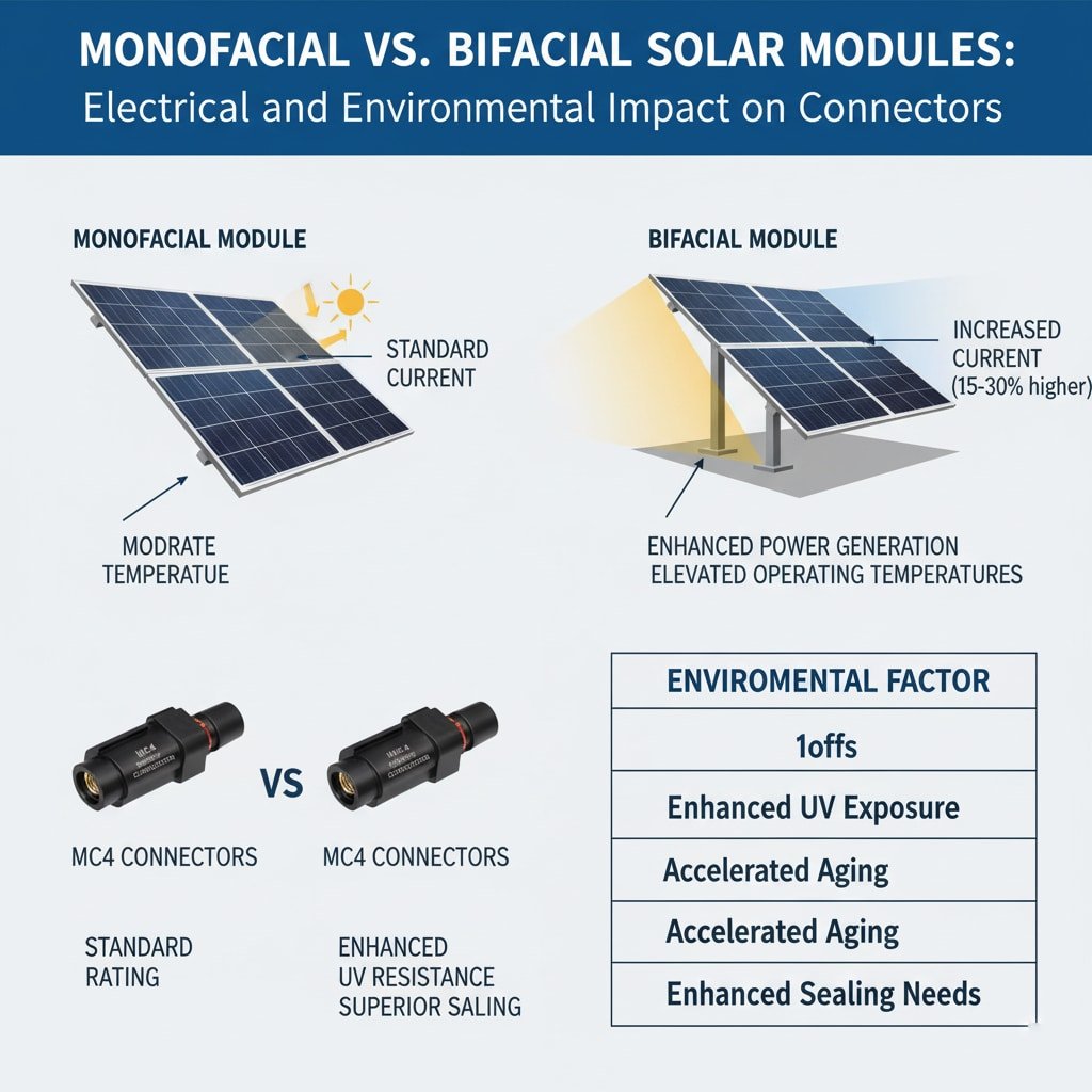
Bifacial solar modules generate significantly higher electrical output through dual-sided energy capture, creating increased current flows that can exceed standard MC4 connector ratings by 15-30%. The enhanced power generation from both front and rear surfaces results in elevated operating temperatures, increased thermal cycling stress, and higher voltage potentials that demand specialized connector specifications. Additionally, bifacial installations often utilize reflective mounting systems and elevated structures that expose connections to enhanced UV radiation, moisture, and environmental stress requiring superior material properties and sealing performance for long-term reliability.
Enhanced Electrical Characteristics
Higher Current Generation: Bifacial modules typically produce 10-25% more current than equivalent monofacial panels, requiring connectors rated for increased ampacity.
Elevated Voltage Levels: Enhanced power output results in higher system voltages that stress connector insulation and require superior dielectric properties.
Increased Power Density: Higher electrical output per module creates concentrated power flows through connection points, demanding enhanced thermal management.
Dynamic Load Variations: Bifacial output varies with ground reflectance and sun angle, creating variable electrical stress on connector components.
Thermal Management Challenges
Dual-Surface Heat Generation: Both module surfaces contribute to thermal loading, creating higher ambient temperatures around connection points.
Enhanced Thermal Cycling: Greater temperature swings from increased power generation accelerate material fatigue and connection degradation.
Heat Concentration: Higher power densities create localized heating that can exceed standard connector temperature ratings.
Thermal Expansion Stress: Increased temperature variations cause greater mechanical stress on connector housings and sealing components.
Environmental Exposure Factors
| Environmental Factor | Standard Modules | Bifacial Modules | Impact on Connectors |
|---|---|---|---|
| UV Exposure | Front surface only | Both surfaces | Increased degradation |
| Thermal Cycling | Moderate | Enhanced | Accelerated aging |
| Moisture Exposure | Standard | Elevated structures | Enhanced sealing needs |
| Mechanical Stress | Normal | Wind loading | Stronger mounting required |
Installation Configuration Differences
Elevated Mounting: Bifacial modules often use elevated mounting systems that expose connections to increased wind loading and environmental stress.
Reflective Surfaces: Ground-mounted systems frequently incorporate reflective materials that increase ambient light and temperature around connections.
Tracking Systems: Many bifacial installations use tracking systems that create dynamic mechanical stress on electrical connections.
Spacing Requirements: Optimized row spacing for bifacial gain may affect cable routing and connection accessibility for maintenance.
Power Output Variability
Time-of-Day Variations: Bifacial output patterns differ from monofacial modules, creating unique electrical stress profiles on connectors.
Seasonal Changes: Ground reflectance variations throughout the year cause fluctuating power output and thermal cycling.
Weather Dependencies: Cloud conditions and atmospheric factors affect rear-side irradiance and create variable electrical loading.
Site-Specific Factors: Ground conditions, nearby structures, and installation geometry significantly impact bifacial performance and connector requirements.
Working with Ahmed Hassan, chief engineer at a major solar developer in Dubai, UAE, I learned that bifacial installations in desert environments create particularly challenging conditions for MC4 connectors due to extreme temperature variations, high UV exposure, and reflective sand surfaces that can increase module output by 35% while creating severe thermal stress on connection components! 🌞
Which MC4 Connectors Are Best for Bifacial Applications?
Selecting appropriate MC4 connectors for bifacial modules requires understanding enhanced specifications and performance requirements.
High-performance MC4 connectors for bifacial applications must feature current ratings of 15-20A minimum (vs. standard 10-13A), operating temperature ranges of -40°C to +105°C, enhanced UV-resistant materials with 25+ year outdoor ratings, and superior contact materials like tin-plated copper or silver-plated contacts for optimal conductivity and corrosion resistance. Premium connectors also incorporate advanced sealing technologies, reinforced housing designs, and specialized cable strain relief systems that withstand the increased mechanical and thermal stress inherent in bifacial installations while maintaining IP67/IP68 protection ratings.
Enhanced Current Rating Requirements
Standard vs. Bifacial Ratings: Standard MC4 connectors rated for 10-13A may be inadequate for bifacial applications requiring 15-20A capacity.
Safety Margins: Proper connector selection includes 25-30% current derating for long-term reliability and thermal management.
Ampacity2 Calculations: Consider maximum bifacial gain potential (up to 30%) when calculating required connector current ratings.
Future Expansion: Select connectors with capacity for potential system upgrades or enhanced bifacial performance improvements.
Temperature Performance Specifications
Operating Range: Bifacial connectors should handle -40°C to +105°C continuous operation with peak ratings to +120°C.
Thermal Cycling: Enhanced thermal cycling resistance prevents connection degradation from repeated heating and cooling.
Heat Dissipation: Advanced connector designs incorporate heat sinks or thermal management features for improved performance.
Contact Stability: Temperature-stable contact materials maintain low resistance across full operating temperature range.
Material Enhancement Requirements
| Component | Standard Specification | Bifacial Enhancement | Performance Benefit |
|---|---|---|---|
| Housing Material | Standard PA66 | UV-stabilized PA66+GF | Extended UV life |
| Contact Material | Tin-plated copper | Silver-plated copper | Lower resistance |
| Sealing System | Standard EPDM | Premium fluoroelastomer3 | Enhanced durability |
| Cable Insulation | Standard PV wire | Enhanced UV-rated | Longer service life |
Advanced Sealing Technologies
IP68 Rating: Superior sealing protection prevents moisture ingress under elevated pressure conditions common in bifacial installations.
Gasket Materials: Premium elastomer compounds resist UV degradation, thermal cycling, and chemical exposure over 25+ year lifetimes.
Multi-Stage Sealing: Advanced designs incorporate multiple sealing barriers for redundant protection against environmental ingress.
Pressure Relief: Some designs include pressure equalization features that prevent seal damage from thermal expansion.
Mechanical Strength Improvements
Housing Reinforcement: Enhanced housing designs resist cracking and deformation under increased thermal and mechanical stress.
Strain Relief: Advanced cable strain relief systems prevent conductor fatigue from wind loading and thermal movement.
Locking Mechanisms: Reinforced locking systems maintain secure connections under dynamic loading conditions.
Vibration Resistance: Enhanced designs resist loosening from wind-induced vibration and tracking system movement.
Quality Certifications
IEC Standards: Look for IEC 62852 compliance specifically for photovoltaic applications with enhanced performance requirements.
UL Listings: UL 6703 listing ensures compliance with North American safety standards for solar connectors.
TUV Certification: TUV approval provides European market access and validates performance under stringent testing protocols.
Extended Testing: Premium connectors undergo additional thermal cycling, UV exposure, and mechanical stress testing beyond standard requirements.
At Bepto, we’ve developed specialized MC4 connectors specifically engineered for bifacial applications, featuring 20A current ratings, -40°C to +105°C operating ranges, and advanced UV-resistant materials that exceed standard specifications by 40% to ensure optimal performance and reliability in demanding bifacial installations! 🔌
How Do Installation Requirements Change with Bifacial Modules?
Bifacial module installations require modified techniques and enhanced procedures to ensure optimal MC4 connector performance and reliability.
Bifacial module installations demand enhanced cable management with increased service loops for thermal expansion, elevated connector positioning to prevent ground contact and moisture exposure, specialized torque specifications adjusted for higher thermal cycling stress, and comprehensive testing protocols that verify both electrical performance and mechanical integrity under dynamic loading conditions. Installation teams must also implement enhanced quality control measures including thermal imaging verification, pull-testing of connections, and documentation procedures that account for the unique performance characteristics and warranty requirements of bifacial technology.
Cable Management Considerations
Service Loop Requirements: Provide additional cable length to accommodate greater thermal expansion from increased operating temperatures.
Routing Protection: Protect cables from enhanced UV exposure and mechanical damage in elevated mounting configurations.
Connector Positioning: Position MC4 connections away from reflective surfaces and high-temperature zones to minimize thermal stress.
Accessibility Planning: Ensure adequate access for maintenance while protecting connections from environmental exposure.
Enhanced Installation Procedures
Pre-Installation Inspection: Verify connector ratings and specifications match bifacial module requirements before installation begins.
Torque Specifications: Apply manufacturer-specified torque values with consideration for enhanced thermal cycling conditions.
Sealing Verification: Ensure proper gasket compression and sealing integrity to handle increased environmental stress.
Connection Testing: Perform comprehensive electrical testing including continuity, insulation resistance, and thermal imaging verification.
Quality Control Enhancements
| Installation Phase | Standard Procedure | Bifacial Enhancement | Verification Method |
|---|---|---|---|
| Pre-Installation | Visual inspection | Connector rating verification | Documentation review |
| During Installation | Torque application | Enhanced torque procedures | Calibrated tools |
| Post-Installation | Continuity testing | Thermal imaging scan | IR thermography |
| Final Verification | System commissioning | Performance validation | Power output testing |
Environmental Protection Measures
UV Shielding: Implement additional UV protection for connectors exposed to enhanced radiation from reflective surfaces.
Moisture Management: Enhanced sealing procedures and drainage considerations for elevated installations with increased exposure.
Temperature Monitoring: Install temperature monitoring systems to track connector performance under enhanced thermal conditions.
Mechanical Support: Provide additional mechanical support for connections subject to wind loading and dynamic stress.
Testing and Commissioning Protocols
Electrical Performance: Verify connector performance under actual bifacial operating conditions with enhanced power output.
Thermal Analysis: Conduct thermal imaging analysis to identify hot spots and verify proper heat dissipation.
Mechanical Testing: Perform pull tests and vibration analysis to ensure connections withstand dynamic loading.
Long-term Monitoring: Implement monitoring systems to track connector performance over time and identify potential issues.
Documentation Requirements
Installation Records: Maintain detailed records of connector specifications, installation procedures, and test results.
Performance Baselines: Establish baseline performance data for future comparison and troubleshooting purposes.
Maintenance Schedules: Develop enhanced maintenance schedules that account for increased stress and wear in bifacial applications.
Warranty Compliance: Ensure installation documentation meets manufacturer warranty requirements for both modules and connectors.
Working with Marcus Weber, installation manager at a leading German solar contractor, I discovered that implementing specialized installation procedures for bifacial projects reduced their connection-related service calls by 75% and improved overall system performance by ensuring optimal electrical and mechanical integrity from day one! 🛠️
What Are the Key Performance and Reliability Considerations?
Understanding performance and reliability factors ensures optimal long-term operation of MC4 connectors in bifacial applications.
Key performance considerations for bifacial MC4 connectors include maintaining low contact resistance under increased current loads to minimize power losses, ensuring thermal stability across enhanced operating temperature ranges to prevent degradation, providing superior corrosion resistance for extended service life in challenging environments, and delivering consistent electrical performance throughout 25+ year system lifetimes. Reliability factors encompass mechanical durability under dynamic loading, sealing integrity against environmental ingress, material stability under enhanced UV exposure, and compatibility with system monitoring requirements for predictive maintenance and performance optimization.
Electrical Performance Metrics
Contact Resistance: Maintain resistance below 0.5 milliohms throughout service life to minimize power losses and heat generation.
Current Carrying Capacity: Ensure continuous operation at rated current without derating due to temperature or environmental factors.
Voltage Withstand: Provide adequate insulation strength for system voltages with appropriate safety margins for transient conditions.
Power Loss Minimization: Optimize connector design to minimize resistive losses that reduce overall system efficiency.
Thermal Management Performance
Heat Dissipation: Effective thermal management prevents hot spots and maintains optimal operating temperatures.
Thermal Cycling Resistance: Withstand repeated heating and cooling cycles without degradation or failure.
Temperature Coefficient: Maintain stable electrical properties across full operating temperature range.
Thermal Imaging Compatibility: Enable accurate thermal monitoring for predictive maintenance programs.
Long-term Reliability Factors
| Reliability Aspect | Performance Metric | Bifacial Requirement | Testing Standard |
|---|---|---|---|
| UV Resistance | Material degradation | <5% after 25 years | ASTM G1544 |
| Thermal Cycling | Contact resistance | <10% increase | IEC 62852 |
| Mechanical Durability | Pull strength | >50N retention | UL 6703 |
| Sealing Integrity | IP rating | IP67/IP68 maintained | IEC 605295 |
Environmental Durability
UV Stability: Resist degradation from enhanced UV exposure in bifacial installations with reflective surfaces.
Moisture Resistance: Maintain sealing integrity under varying humidity and precipitation conditions.
Chemical Compatibility: Resist corrosion from atmospheric pollutants, cleaning agents, and environmental contaminants.
Mechanical Robustness: Withstand wind loading, vibration, and thermal movement without failure.
Performance Monitoring Capabilities
Thermal Monitoring: Enable thermal imaging analysis for predictive maintenance and performance optimization.
Electrical Testing: Support comprehensive electrical testing including insulation resistance and continuity verification.
Visual Inspection: Facilitate visual inspection procedures for identifying potential issues before failure occurs.
Data Integration: Compatibility with system monitoring platforms for comprehensive performance tracking.
Maintenance and Service Considerations
Accessibility: Design connections for easy access during routine maintenance and inspection procedures.
Serviceability: Enable field replacement and repair without specialized tools or extensive system shutdown.
Diagnostic Compatibility: Support diagnostic testing equipment for troubleshooting and performance analysis.
Spare Parts Availability: Ensure long-term availability of replacement components throughout system lifetime.
Quality Assurance Metrics
Manufacturing Consistency: Maintain consistent quality and performance across production batches and time periods.
Field Performance: Track actual field performance data to validate design specifications and identify improvement opportunities.
Failure Analysis: Comprehensive failure analysis programs to identify root causes and implement corrective actions.
Continuous Improvement: Ongoing product development based on field experience and emerging technology requirements.
At Bepto, our bifacial-rated MC4 connectors undergo extensive testing including 2000-hour thermal cycling, enhanced UV exposure equivalent to 30+ years of outdoor service, and mechanical stress testing that exceeds standard requirements by 50% to ensure reliable performance throughout the extended service life demanded by bifacial installations! 📊
How Can You Avoid Common Bifacial Connection Problems?
Preventing common connection problems requires understanding potential failure modes and implementing proactive prevention strategies.
Common bifacial connection problems include thermal overload from inadequate current ratings, premature aging from enhanced UV exposure, mechanical failure from increased thermal cycling, and moisture ingress from inadequate sealing under elevated environmental stress. Prevention strategies encompass proper connector specification with adequate safety margins, enhanced installation procedures including calibrated torque application and comprehensive testing, regular maintenance programs with thermal imaging and electrical verification, and quality control measures that ensure consistent installation standards and early problem detection before catastrophic failures occur.
Thermal-Related Problem Prevention
Proper Current Rating: Select connectors with 25-30% current derating to handle peak bifacial output without thermal stress.
Heat Management: Implement thermal management strategies including proper spacing, ventilation, and heat dissipation measures.
Temperature Monitoring: Regular thermal imaging inspections identify developing hot spots before they cause failures.
Material Selection: Use connectors with enhanced temperature ratings and thermal cycling resistance for bifacial applications.
UV Degradation Prevention
Enhanced Materials: Specify UV-stabilized materials with proven 25+ year outdoor performance in high-radiation environments.
Protection Strategies: Implement UV shielding where possible without compromising system performance or accessibility.
Regular Inspection: Visual inspection programs identify UV degradation before it compromises connector integrity.
Replacement Planning: Proactive replacement schedules based on UV exposure levels and material degradation rates.
Mechanical Failure Prevention
| Problem Type | Root Cause | Prevention Strategy | Monitoring Method |
|---|---|---|---|
| Housing Cracking | Thermal stress | Enhanced materials | Visual inspection |
| Contact Loosening | Vibration/cycling | Proper torque/locking | Electrical testing |
| Cable Fatigue | Mechanical stress | Strain relief design | Pull testing |
| Seal Failure | Environmental stress | Premium sealing | Leak testing |
Moisture and Corrosion Prevention
Superior Sealing: Use IP68-rated connectors with premium gasket materials for enhanced moisture protection.
Drainage Design: Implement proper drainage and water management to prevent moisture accumulation around connections.
Corrosion-Resistant Materials: Select contact materials and coatings that resist corrosion in challenging environments.
Environmental Protection: Provide additional environmental protection where conditions exceed standard exposure levels.
Installation Quality Control
Training Programs: Comprehensive installer training on bifacial-specific requirements and procedures.
Tool Calibration: Regular calibration of torque tools and testing equipment to ensure consistent installation quality.
Documentation Standards: Detailed installation documentation and quality control records for traceability and warranty compliance.
Verification Procedures: Multi-stage verification procedures including electrical testing, thermal imaging, and mechanical inspection.
Maintenance and Monitoring Programs
Preventive Maintenance: Regular inspection and maintenance schedules tailored to bifacial installation requirements.
Performance Monitoring: Continuous monitoring systems that identify performance degradation before failures occur.
Predictive Analytics: Data analysis programs that predict potential failures based on performance trends and environmental conditions.
Emergency Response: Rapid response procedures for addressing identified problems before they impact system performance.
Quality Supplier Selection
Proven Performance: Select suppliers with documented experience and proven performance in bifacial applications.
Technical Support: Ensure availability of technical support and application engineering assistance throughout project lifecycle.
Warranty Coverage: Comprehensive warranty programs that cover performance under bifacial operating conditions.
Continuous Innovation: Partner with suppliers committed to ongoing product development and improvement for emerging applications.
Working with Jennifer Park, operations manager at a major solar O&M company in Seoul, South Korea, I learned that implementing comprehensive prevention programs reduced their bifacial connection failures by 90% and improved overall system availability while reducing maintenance costs significantly through proactive problem identification and resolution! 🔧
Conclusion
Bifacial solar modules represent the future of photovoltaic technology, but their enhanced performance characteristics demand specialized MC4 connector solutions and installation practices. Proper connector selection with adequate current ratings, enhanced materials, and superior thermal management ensures optimal performance and long-term reliability. Understanding the unique requirements of bifacial installations, implementing enhanced installation procedures, and maintaining comprehensive quality control programs prevents common problems and maximizes the significant energy yield benefits that make bifacial technology increasingly attractive for commercial and utility-scale projects. The investment in proper connector specifications and installation practices pays substantial dividends through improved system performance, reduced maintenance costs, and enhanced long-term reliability.
FAQs About Bifacial Modules and MC4 Connectors
Q: Do I need special MC4 connectors for bifacial solar panels?
A: Yes, bifacial modules require MC4 connectors with higher current ratings (15-20A vs. standard 10-13A) and enhanced thermal performance to handle the increased power output. Standard connectors may overheat and fail prematurely in bifacial applications due to higher electrical loads and thermal cycling.
Q: What current rating should I use for bifacial MC4 connectors?
A: Use MC4 connectors rated for at least 15-20A continuous current for bifacial applications. This provides adequate safety margin for the 10-30% higher current output typical of bifacial modules compared to equivalent monofacial panels.
Q: How much more do bifacial-rated MC4 connectors cost?
A: Bifacial-rated MC4 connectors typically cost 20-40% more than standard versions, but this represents less than 0.1% of total system cost while preventing expensive failures and warranty claims. The enhanced reliability and performance justify the modest price premium.
Q: Can I use regular MC4 connectors temporarily on bifacial modules?
A: No, using standard MC4 connectors on bifacial modules creates safety risks including overheating, connection failure, and potential fire hazards. Always use properly rated connectors from initial installation to ensure safety and maintain warranty coverage.
Q: How often should I inspect MC4 connections on bifacial installations?
A: Inspect bifacial MC4 connections annually with thermal imaging and electrical testing, plus visual inspection every 6 months. The enhanced operating conditions require more frequent monitoring than standard installations to identify potential issues early.
-
Learn the technology behind bifacial solar modules, which can capture sunlight and generate electricity from both their front and back sides. ↩
-
Understand the definition of ampacity, the maximum amount of electrical current a conductor or device can carry continuously without exceeding its temperature rating. ↩
-
Explore the properties of fluoroelastomers (FKM), a class of synthetic rubber known for excellent resistance to heat, chemicals, and environmental factors. ↩
-
Review the ASTM G154 standard, a practice for operating fluorescent ultraviolet (UV) lamp apparatus for exposure of nonmetallic materials. ↩
-
Learn about the international standard IEC 60529, which defines the degrees of protection provided by enclosures (IP Code) against intrusion, dust, and water. ↩
