Introduction
Are you experiencing electromagnetic interference (EMI)1 issues, premature cable failures, or compliance problems with your VFD installations? These costly problems often stem from improper cable gland selection – a critical but frequently overlooked aspect of VFD system design. Poor gland choices can lead to system downtime, regulatory violations, and expensive retrofits.
VFD cable gland selection requires EMC-rated glands with 360-degree shielding continuity, proper IP ratings for environmental protection, and materials compatible with VFD-generated heat and electrical stress. The key is matching gland specifications to VFD operating characteristics and installation environment requirements.
As Sales Director at Bepto Connector, I’ve witnessed firsthand how proper cable gland selection transforms VFD performance. Just last week, Marcus, a senior electrical engineer at a major manufacturing facility in Birmingham, UK, contacted us after experiencing recurring EMI issues that were disrupting their production control systems. His challenge – and solution – illustrates why VFD cable gland selection demands specialized engineering knowledge.
Table of Contents
- Why Do VFDs Require Special Cable Gland Considerations?
- What Are the Key Technical Requirements for VFD Cable Glands?
- How Do You Select the Right Cable Gland Type for VFDs?
- What Are Common VFD Cable Gland Selection Mistakes?
- How Do Environmental Factors Impact VFD Gland Selection?
- FAQs About VFD Cable Glands
Why Do VFDs Require Special Cable Gland Considerations?
Variable Frequency Drives generate high-frequency switching noise, electromagnetic interference, and elevated temperatures that demand specialized cable gland solutions beyond standard industrial applications. Understanding these unique challenges is essential for proper gland selection and system reliability.
VFD Operating Characteristics That Impact Cable Glands
High-Frequency Switching Noise
VFDs use pulse-width modulation (PWM)2 switching at frequencies typically ranging from 2kHz to 16kHz. This switching creates high-frequency common-mode voltages that can reach several thousand volts, traveling along cable shields and seeking ground paths through cable glands. Without proper EMC glands, this energy radiates as electromagnetic interference or creates circulating currents that damage bearings and other system components.
Elevated Operating Temperatures
VFD installations often generate significant heat, with enclosure temperatures reaching 60-80°C in industrial environments. Cable glands must maintain sealing integrity and mechanical properties across these temperature ranges while handling thermal cycling effects that can cause standard elastomers to degrade prematurely.
Electrical Stress on Cable Systems
The rapid voltage transitions in VFD output waveforms create electrical stress on cable insulation and termination points. Cable glands must provide reliable grounding continuity while protecting against voltage breakdown at termination points where electric field concentrations occur.
EMC Compliance Requirements
Modern VFD installations must comply with electromagnetic compatibility standards including:
- IEC 61800-33: EMC requirements for adjustable speed electrical power drive systems
- EN 55011: Industrial, scientific and medical equipment radio disturbance characteristics
- FCC Part 15: Radio frequency emission limits for industrial equipment
Marcus’s facility in Birmingham faced exactly these challenges. Their new production line included twelve 75kW VFDs controlling conveyor systems, but standard cable glands were allowing EMI to interfere with nearby PLC communications. “We were getting random faults every few hours,” Marcus explained. “The production manager was ready to scrap the entire VFD upgrade project.”
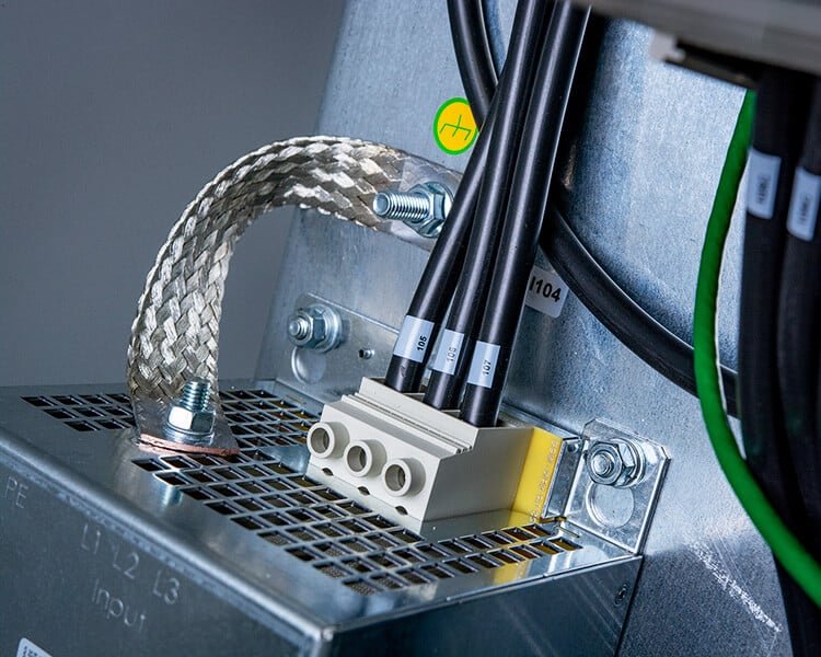
Grounding and Shielding Continuity
360-Degree Shield Termination
Effective EMI control requires continuous shield termination around the complete cable circumference. Standard cable glands often create shield discontinuities that allow high-frequency noise to escape, while EMC-rated glands maintain shield integrity through specialized conductive gaskets and compression mechanisms.
Low-Impedance Ground Paths
VFD-generated common-mode currents require low-impedance paths to ground. Cable glands must provide reliable electrical continuity between cable shields and equipment enclosures while maintaining this connection despite vibration, thermal cycling, and long-term environmental exposure.
At Bepto, our EMC cable glands incorporate conductive elastomers and specialized compression designs that maintain shield continuity even under extreme conditions. Our TUV-certified testing validates EMC performance across frequency ranges from 150kHz to 1GHz, ensuring compliance with international standards.
What Are the Key Technical Requirements for VFD Cable Glands?
Understanding specific technical requirements helps engineers select glands that ensure reliable VFD operation and regulatory compliance.
EMC Performance Specifications
Shielding Effectiveness Requirements
VFD cable glands should provide minimum shielding effectiveness of 60dB across the frequency range from 10MHz to 1GHz. This performance level ensures adequate suppression of VFD-generated EMI while maintaining signal integrity in nearby control circuits.
Transfer Impedance Characteristics
Low transfer impedance (typically <1mΩ/m at 100MHz) ensures effective common-mode current handling without creating voltage drops that could affect system performance or create additional EMI sources.
Material Selection Criteria
Conductive Elastomers
EMC glands require specialized elastomeric compounds incorporating conductive fillers such as silver-plated copper particles or carbon black. These materials maintain conductivity while providing environmental sealing, with typical volume resistivity values below 0.1 Ω·cm.
Corrosion-Resistant Metals
Gland bodies and hardware must resist galvanic corrosion4 when connecting different metal types common in VFD installations. Stainless steel 316L or nickel-plated brass provides excellent corrosion resistance while maintaining electrical conductivity.
Temperature-Stable Polymers
Sealing elements must maintain properties across VFD operating temperature ranges. High-performance elastomers like FKM (Viton) or EPDM compounds rated for continuous operation at 125°C ensure long-term reliability in demanding thermal environments.
Mechanical Performance Standards
Vibration Resistance
VFD installations often experience significant vibration from connected motors and mechanical equipment. Cable glands must maintain secure cable retention and electrical continuity despite vibration levels up to 10g RMS across frequency ranges from 10Hz to 2kHz.
Pull-Out Force Requirements
Minimum cable retention forces of 500N for power cables and 200N for control cables ensure connections remain secure despite thermal expansion, building movement, or accidental cable tension.
Environmental Protection Ratings
IP Rating Selection
Most VFD installations require minimum IP65 protection, with IP66 or IP67 ratings preferred for harsh industrial environments. Washdown applications or outdoor installations may require IP68 or IP69K ratings for complete submersion or high-pressure cleaning resistance.
Chemical Compatibility
Industrial environments expose cable glands to various chemicals including cutting fluids, hydraulic oils, and cleaning solvents. Gland materials must resist degradation from these exposures while maintaining sealing and EMC performance.
Hassan, who manages a petrochemical facility in Kuwait, recently upgraded their VFD systems with our stainless steel EMC glands. “The combination of chemical resistance and EMC performance was exactly what we needed,” he reported. “Six months later, we’ve had zero EMI issues and the glands show no signs of chemical attack despite exposure to process chemicals.”
How Do You Select the Right Cable Gland Type for VFDs?
Systematic gland selection ensures optimal VFD performance while avoiding costly specification mistakes that compromise system reliability.
Step 1: Analyze VFD System Requirements
Power Rating and Voltage Classification
Higher power VFDs generate more EMI and require more robust EMC solutions. Systems above 50kW typically need premium EMC glands with enhanced shielding effectiveness, while smaller drives may operate successfully with standard EMC-rated glands.
Switching Frequency Considerations
VFDs operating at higher switching frequencies (>8kHz) generate more high-frequency EMI requiring glands with superior shielding performance across extended frequency ranges. Lower switching frequencies may allow more economical gland solutions while still meeting EMC requirements.
Step 2: Evaluate Cable Types and Configurations
Shielded vs. Unshielded Cables
Shielded VFD cables require EMC glands that properly terminate the shield, while unshielded cables may use standard industrial glands in less demanding applications. However, most modern VFD installations benefit from shielded cables and appropriate EMC glands regardless of power level.
Cable Construction Details
- Armored cables require glands that accommodate armor termination while maintaining EMC performance
- Multi-core cables need glands sized for overall cable diameter with proper compression characteristics
- Separate control cables may require different gland specifications than power cables
Step 3: Assess Environmental Conditions
Temperature Range Analysis
Ambient temperatures plus VFD heat generation determine required gland temperature ratings. Conservative design practice adds 20°C margin to calculated maximum temperatures, ensuring reliable operation during peak load conditions.
Contamination and Chemical Exposure
Industrial environments expose glands to various contaminants requiring appropriate material selection:
- Oil and grease exposure: Requires NBR or FKM elastomers
- Chemical processing: Demands PTFE or specialized chemical-resistant compounds
- Food processing: Needs FDA-approved materials with easy cleaning characteristics
Step 4: Consider Installation and Maintenance Factors
Accessibility for Installation
Complex installations may benefit from glands with simplified installation procedures, even if unit costs are higher. Time savings during installation often offset premium gland costs, especially in retrofit applications with limited access.
Long-term Serviceability
Glands in difficult-to-access locations should prioritize long-term reliability over initial cost savings. Premium materials and construction justify higher costs when replacement requires significant downtime or labor expense.
Material Selection Matrix
| Application | Gland Body | Sealing Element | Special Features |
|---|---|---|---|
| Standard Industrial | Nickel-plated Brass | NBR | EMC gasket, IP65 |
| Chemical Processing | Stainless Steel 316L | FKM/Viton | Chemical resistance, IP67 |
| Food Processing | Stainless Steel 316L | FDA Silicone | Hygienic design, IP69K |
| Marine/Offshore | Stainless Steel 316L | EPDM | Saltwater resistance, IP68 |
| High Temperature | Stainless Steel 316L | FKM/Viton | 150°C rating, thermal cycling |
What Are Common VFD Cable Gland Selection Mistakes?
Learning from common mistakes helps engineers avoid costly specification errors that compromise VFD system performance and reliability.
Mistake 1: Using Standard Glands for EMC Applications
The Problem
Many engineers specify standard industrial cable glands for VFD installations, assuming basic environmental protection is sufficient. Standard glands lack EMC shielding capabilities, allowing high-frequency noise to radiate and interfere with nearby equipment.
Real-World Consequences
- Random PLC communication errors
- Premature bearing failures in connected motors
- Regulatory compliance violations
- Interference with radio communications
The Solution
Always specify EMC-rated cable glands for VFD power and control cables. Even if initial EMI testing appears acceptable, system modifications or additional equipment installations can change EMC characteristics, making proper glands essential for long-term reliability.
Mistake 2: Inadequate Temperature Ratings
The Problem
Underestimating operating temperatures leads to premature seal failure and compromised EMC performance. Many engineers calculate ambient temperatures but ignore heat generation from VFDs and other equipment in the same enclosure.
Marcus’s Experience
At the Birmingham facility, initial gland specifications used standard NBR seals rated for 80°C. However, VFD enclosure temperatures reached 85°C during summer operation, causing seal degradation and EMI leakage within six months. Upgrading to FKM seals rated for 125°C eliminated these problems.
Prevention Strategy
- Measure actual operating temperatures during peak conditions
- Add 20°C safety margin to measured temperatures
- Consider thermal cycling effects on seal materials
- Specify premium elastomers for demanding applications
Mistake 3: Ignoring Cable Shield Termination Requirements
The Problem
Improper shield termination creates EMI leakage paths and can cause circulating currents that damage VFD systems. Some installations attempt to save costs by using standard glands with improvised shield connections.
Technical Consequences
- Reduced shielding effectiveness
- Common-mode current circulation
- Bearing damage from electrical discharge machining (EDM)5
- Increased radiated emissions
Proper Shield Termination
EMC glands must provide 360-degree shield contact with low transfer impedance. Shield connections should be as short as possible with minimal impedance to the equipment ground reference.
Mistake 4: Overlooking Long-term Reliability
The Problem
Focusing solely on initial cost without considering lifecycle expenses often leads to premature failures and expensive retrofits. Cheap glands may require replacement every 2-3 years, while premium glands can operate reliably for 10+ years.
Cost Analysis Example
A major automotive plant initially saved $15,000 by specifying economy glands for 200 VFD installations. However, premature failures required complete replacement after 30 months, costing $45,000 in materials plus $25,000 in labor and downtime. Premium glands would have provided 10-year service life at $35,000 initial cost.
How Do Environmental Factors Impact VFD Gland Selection?
Environmental conditions significantly influence gland material selection, sealing requirements, and long-term performance characteristics.
Temperature Considerations
Continuous Operating Temperature
VFD installations create elevated ambient temperatures through power dissipation and switching losses. Gland sealing elements must maintain properties across the full temperature range while resisting thermal aging effects.
Thermal Cycling Effects
Repeated heating and cooling cycles stress gland materials through differential thermal expansion. Premium elastomers like FKM maintain sealing integrity through thousands of thermal cycles, while economy materials may fail after hundreds of cycles.
Temperature Rating Guidelines
- Standard applications: 105°C continuous rating minimum
- Demanding environments: 125°C continuous rating recommended
- Extreme conditions: 150°C rating with specialized materials
Chemical Exposure Assessment
Common Industrial Chemicals
VFD installations encounter various chemicals that can degrade standard gland materials:
Hydraulic Fluids: Petroleum-based fluids attack NBR elastomers but have minimal effect on FKM compounds. Synthetic hydraulic fluids may require specialized chemical compatibility analysis.
Cutting Fluids and Coolants: Water-based coolants with additives can cause swelling in some elastomers while promoting corrosion in metal components. Stainless steel glands with appropriate elastomer selection prevent these problems.
Cleaning Solvents: Aggressive cleaning chemicals used in food processing and pharmaceutical applications require specialized material selection and may mandate IP69K ratings for high-pressure washdown resistance.
Vibration and Mechanical Stress
Source Analysis
VFD installations experience vibration from multiple sources:
- Connected motor vibration transmitted through cable conduits
- Building vibration from nearby heavy equipment
- Thermal expansion and contraction creating mechanical stress
Gland Design Response
Robust gland designs incorporate features to handle mechanical stress:
- Multiple compression zones distribute stress more evenly
- Premium materials resist fatigue from repeated flexing
- Secure cable retention prevents pullout under dynamic loading
Hassan’s petrochemical facility in Kuwait experiences significant vibration from nearby compressor equipment. “Our original glands loosened within months due to vibration,” he explained. “Bepto’s heavy-duty EMC glands have maintained tight connections for over two years despite constant vibration exposure.”
Moisture and Contamination Protection
IP Rating Selection Strategy
VFD installations require careful IP rating analysis based on specific exposure conditions:
IP65: Adequate for indoor installations with occasional washdown or dust exposure
IP66: Recommended for most industrial VFD applications with regular cleaning requirements
IP67: Required for outdoor installations or areas with temporary water exposure
IP68: Essential for applications with potential submersion or continuous moisture exposure
IP69K: Mandatory for food processing and pharmaceutical applications requiring high-pressure, high-temperature washdown
Atmospheric Corrosion Factors
Salt Air Exposure
Coastal and marine environments create corrosive conditions requiring stainless steel gland construction with appropriate elastomer selection. Standard brass glands suffer rapid corrosion in salt air environments.
Industrial Atmospheric Contamination
Chemical processing facilities and heavy industrial areas expose glands to corrosive atmospheric contaminants. Material selection must consider both direct chemical contact and atmospheric exposure effects.
Conclusion
Proper cable gland selection is critical for VFD system reliability, EMC compliance, and long-term performance. The unique challenges of VFD installations – including high-frequency EMI, elevated temperatures, and demanding environmental conditions – require specialized gland solutions that go beyond standard industrial applications.
Success depends on systematic analysis of VFD operating characteristics, environmental conditions, and long-term reliability requirements. While premium EMC-rated glands require higher initial investment, they deliver superior performance and lower total cost of ownership through reduced maintenance, improved reliability, and regulatory compliance.
At Bepto Connector, our comprehensive range of EMC cable glands provides solutions for every VFD application, from standard industrial installations to the most demanding chemical processing and marine environments. Our ISO9001 and TUV certifications ensure consistent quality, while our extensive testing capabilities validate performance in your specific application conditions.
Remember: VFD cable gland selection is an investment in system reliability. Choose glands that match your VFD’s unique requirements, and your installation will deliver years of trouble-free operation with optimal EMC performance.
FAQs About VFD Cable Glands
Q: Do I really need EMC cable glands for small VFDs under 10kW?
A: Yes, even small VFDs generate high-frequency switching noise that can interfere with sensitive control equipment. EMC glands provide essential shielding continuity and are often required for regulatory compliance regardless of VFD size. The small cost difference is easily justified by improved system reliability.
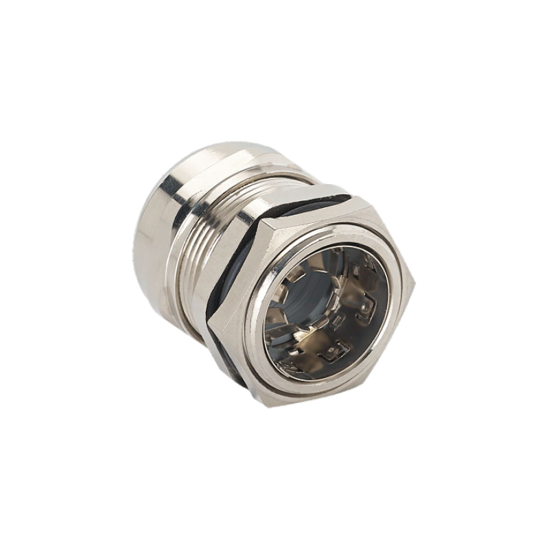
Q: What’s the difference between EMC cable glands and regular industrial glands?
A: EMC cable glands include conductive gaskets and specialized compression mechanisms that maintain 360-degree shield continuity and provide electromagnetic shielding. Regular glands only offer environmental sealing without EMC protection, making them unsuitable for VFD applications where EMI control is critical.
Q: Can I use plastic cable glands for VFD installations?
A: No, plastic glands cannot provide the electrical continuity and EMC shielding required for VFD applications. Metal glands with conductive sealing elements are essential for proper shield termination and grounding continuity in VFD systems.
Q: How do I know what IP rating I need for my VFD installation?
A: Consider your environment’s moisture, dust, and cleaning requirements. Indoor installations typically need IP65-IP66, outdoor applications require IP67 minimum, and washdown areas need IP68 or IP69K. When in doubt, choose a higher rating for better long-term protection.
Q: Why are VFD cable glands more expensive than standard glands?
A: VFD glands require specialized conductive materials, precision manufacturing for EMC performance, and extensive testing for compliance certification. However, their superior performance prevents costly EMI problems, equipment damage, and regulatory violations, making them cost-effective for VFD applications.
-
Learn the fundamental principles of Electromagnetic Interference (EMI) and how it affects electronic systems. ↩
-
Explore the technical details of Pulse-Width Modulation (PWM), the core technology VFDs use to control motor speed. ↩
-
Review the official overview of the IEC 61800-3 standard, which defines EMC requirements for power drive systems. ↩
-
Understand the electrochemical process of galvanic corrosion and why it is a critical factor in selecting dissimilar metals. ↩
-
Discover how stray VFD currents can cause Electrical Discharge Machining (EDM) damage in motor bearings. ↩