

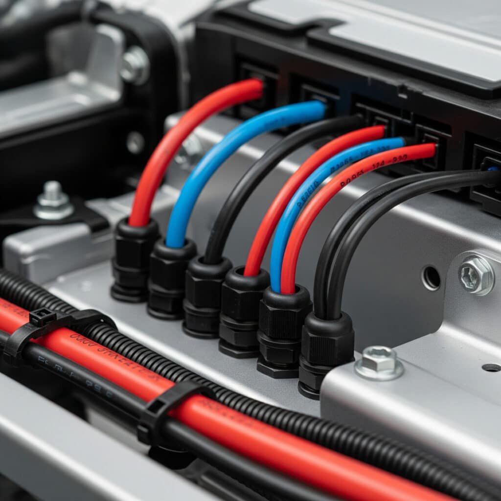
Cable failures during short circuits can generate forces exceeding 50,000N per meter, turning unsecured cables into destructive whips that destroy equipment and endanger personnel. When cables aren’t properly secured with cleats and sealed with appropriate glands, the combination of mechanical stress and environmental ingress creates a perfect storm for catastrophic electrical failures.
Cable cleats are mechanical restraint systems that secure cables against electromagnetic forces1 during fault conditions, while cable glands provide environmental sealing at cable entry points – together they form a complete cable management solution where cleats handle mechanical protection and glands ensure ingress protection, with proper coordination between both systems being essential for electrical safety and reliability. This integrated approach prevents both mechanical cable damage and environmental contamination.
In my decade of experience with cable management systems, I’ve witnessed too many installations where engineers focus solely on cable glands while neglecting proper cable restraint. The result? Expensive equipment damage, safety incidents, and regulatory violations that could have been prevented with proper understanding of how cleats and glands work together.
Table of Contents
- What Are Cable Cleats and How Do They Differ from Cable Glands?
- Why Do Cable Cleats and Cable Glands Need to Work Together?
- How Do You Select Compatible Cable Cleats and Cable Glands?
- What Are the Installation Best Practices for Combined Systems?
- Which Industries Require Both Cable Cleats and Cable Glands?
- FAQs About Cable Cleats and Cable Glands
What Are Cable Cleats and How Do They Differ from Cable Glands?
Understanding the fundamental differences between cable cleats and cable glands is essential for designing effective cable management systems that provide both mechanical protection and environmental sealing.
Cable cleats are mechanical restraint devices designed to secure cables against electromagnetic forces during short circuit conditions, typically rated for forces up to 50kN/m, while cable glands are sealing components that provide environmental protection at cable entry points with IP ratings up to IP682 – cleats focus on mechanical restraint while glands focus on ingress protection. Both serve critical but distinct functions in electrical installations.
Cable Cleat Fundamentals
Primary Function: Mechanical restraint against electromagnetic forces during fault conditions
Key Features:
- Force ratings from 5kN/m to 50kN/m depending on application
- Materials include stainless steel, aluminum, and reinforced polymers
- Designed to withstand peak fault currents without cable movement
- Installation spacing calculated based on cable size and fault current levels
Types of Cable Cleats:
- Single Cable Cleats: For individual cable restraint
- Trefoil Cleats: For three-phase cable groupings
- Ladder Cleats: For multiple cable runs
- Heavy Duty Cleats: For high fault current applications
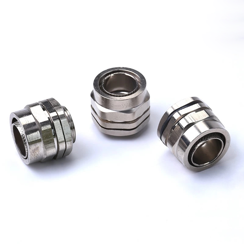
Cable Gland Fundamentals
Primary Function: Environmental sealing and cable entry management
Key Features:
- IP ratings from IP54 to IP68 for various environmental conditions
- Materials include nylon, brass, stainless steel for different applications
- Strain relief and cable grip functionality
- Thread options including metric, NPT, and PG threads
Types of Cable Glands:
- Standard Glands: Basic sealing for general applications
- Armored Cable Glands: For SWA and steel tape armored cables
- Explosion-proof Glands: For hazardous area applications
- EMC Glands: For electromagnetic compatibility requirements
Functional Differences
| Aspect | Cable Cleats | Cable Glands |
|---|---|---|
| Primary Purpose | Mechanical restraint | Environmental sealing |
| Force Rating | Up to 50kN/m | Minimal (strain relief only) |
| IP Rating | Not applicable | IP54 to IP68 |
| Installation Location | Cable runs and supports | Panel/enclosure entry points |
| Standards | IEC 619143 | IEC 62444, various national standards |
| Fault Current Consideration | Critical design parameter | Not directly relevant |
| Environmental Protection | None | Primary function |
When Both Are Required
Most industrial electrical installations require both cable cleats and cable glands because they address different aspects of cable management:
Cable Cleats Handle:
- Short circuit electromagnetic forces
- Mechanical support during normal operation
- Prevention of cable whip and damage
- Compliance with fault current withstand requirements
Cable Glands Handle:
- Water and dust ingress protection
- Chemical and UV resistance
- Strain relief at termination points
- Maintaining enclosure integrity ratings
I remember working with Marcus, a plant engineer at a chemical facility in Rotterdam, who initially questioned why he needed both cleats and glands for his new motor control center installation. After explaining that the cleats would protect against the 25kA fault current his system could experience, while the glands would prevent the corrosive chemical vapors from entering his control panels, he understood that each component served a critical but different protective function. His installation has now operated flawlessly for four years in one of Europe’s most challenging industrial environments.
Why Do Cable Cleats and Cable Glands Need to Work Together?
The integration of cable cleats and cable glands creates a comprehensive cable management system that addresses both mechanical and environmental protection requirements in electrical installations.
Cable cleats and cable glands must work together because cleats prevent mechanical damage that could compromise gland sealing integrity, while glands protect the electrical connections that cleats are designed to preserve – failure of either component can lead to system-wide electrical failures, safety hazards, and regulatory non-compliance. Their coordinated operation ensures complete cable protection from entry point to termination.
Mechanical Protection Synergy
Force Distribution Management:
During fault conditions, electromagnetic forces try to move cables violently. Without proper cleat restraint, these forces transfer directly to cable glands, potentially:
- Breaking gland threads and sealing surfaces
- Pulling cables out of gland grip ranges
- Compromising enclosure integrity
- Creating arc flash hazards4 at connection points
Proper cleat installation distributes these forces across multiple support points, protecting gland connections from mechanical stress.
Environmental Protection Coordination
Sealed System Integrity:
Cable glands create environmental barriers, but their effectiveness depends on stable cable positioning. Cable movement from inadequate restraint can:
- Fatigue gland sealing elements
- Create micro-gaps in environmental barriers
- Allow ingress of moisture, dust, and chemicals
- Compromise long-term sealing performance
Strategic cleat placement maintains cable stability, ensuring gland seals remain effective throughout the installation’s service life.
System-Level Protection Benefits
Cascading Failure Prevention:
When cleats and glands work together properly, they prevent cascading failures:
- Fault Current Event: High electromagnetic forces generated
- Cleat Response: Forces distributed across restraint points
- Gland Protection: Sealing integrity maintained under stress
- System Continuity: Electrical connections remain secure
- Environmental Barrier: Ingress protection continues functioning
Without proper coordination:
- Fault Current Event: Same electromagnetic forces
- Inadequate Restraint: Forces concentrate at gland connections
- Gland Failure: Sealing compromised, connections damaged
- Secondary Failures: Environmental ingress causes additional faults
- System Shutdown: Multiple failure modes cascade
Regulatory Compliance Integration
Standards Coordination:
Modern electrical standards recognize the need for integrated cable management:
- IEC 61914 (Cable Cleats): Specifies mechanical restraint requirements
- IEC 62444 (Cable Glands): Defines sealing and ingress protection
- IEC 60364 (Electrical Installations)5: Requires both mechanical and environmental protection
- National Codes: Often mandate coordinated cable management approaches
Compliance Benefits:
- Simplified inspection and certification processes
- Reduced liability and insurance costs
- Enhanced safety performance records
- Improved regulatory approval timelines
Cost-Effectiveness of Integration
Lifecycle Cost Analysis:
While integrated cleat and gland systems require higher initial investment, they deliver superior long-term value:
Initial Costs:
- Premium for coordinated component selection
- Additional engineering for system integration
- Training for installation teams
Lifecycle Savings:
- 90% reduction in cable-related failures
- Eliminated emergency repair costs
- Reduced maintenance requirements
- Extended equipment service life
- Lower insurance premiums
Hassan, the maintenance director at a petrochemical complex in Saudi Arabia, learned this lesson when his facility experienced three major cable failures in six months. Each incident cost over $500,000 in lost production and emergency repairs. After implementing our integrated cable cleat and gland system throughout the facility, they’ve had zero cable-related failures in two years, with the system paying for itself within 18 months through eliminated downtime costs.
How Do You Select Compatible Cable Cleats and Cable Glands?
Selecting compatible cable cleats and cable glands requires careful consideration of mechanical, environmental, and electrical parameters to ensure optimal system performance and regulatory compliance.
Compatible cable cleat and gland selection involves matching cable specifications, environmental conditions, fault current ratings, and installation constraints while ensuring both components can accommodate the same cable types, sizes, and armor configurations without creating mechanical interference or compromising protective functions. Proper selection prevents component conflicts and maximizes system reliability.
Cable Specification Matching
Cable Type Compatibility:
Both cleats and glands must accommodate the same cable characteristics:
Single Core Cables:
- Cleat spacing: Calculated based on fault current and cable size
- Gland selection: Standard cable glands with appropriate IP rating
- Coordination: Ensure cleat restraint doesn’t interfere with gland strain relief
Multi-Core Cables:
- Cleat configuration: Single or trefoil arrangements based on installation
- Gland requirements: Larger entry sizes, enhanced strain relief
- Integration: Coordinate cable bend radius requirements
Armored Cables (SWA/AWA):
- Cleat considerations: Higher clamping forces for armored constructions
- Gland requirements: Armored cable glands with earth continuity
- Compatibility: Ensure cleat clamping doesn’t damage armor termination
Environmental Condition Coordination
Indoor Applications:
- Temperature Range: -5°C to +40°C typical
- Cleat Materials: Aluminum or steel with appropriate coatings
- Gland Selection: Nylon or brass with standard IP ratings
- Integration Focus: Mechanical performance and cost optimization
Outdoor Applications:
- Temperature Range: -40°C to +85°C extended
- Cleat Materials: Stainless steel or UV-stabilized polymers
- Gland Selection: Marine-grade materials with enhanced UV resistance
- Integration Focus: Weather resistance and thermal cycling
Hazardous Areas:
- Certification Requirements: ATEX/IECEx for both components
- Cleat Specifications: Non-sparking materials, certified designs
- Gland Requirements: Explosion-proof or increased safety ratings
- Integration Standards: Coordinated certification documentation
Fault Current Coordination
Fault Current Calculation:
Proper cleat selection requires accurate fault current analysis:
System Parameters:
- Maximum prospective fault current (kA)
- Fault duration (typically 0.1 to 1.0 seconds)
- Cable configuration and spacing
- Support structure characteristics
Cleat Rating Selection:
- Force rating must exceed calculated electromagnetic forces
- Safety factors typically 1.5 to 2.0 times calculated forces
- Consider peak and RMS current values
- Account for cable movement and dynamic effects
Gland Coordination:
While glands don’t directly handle fault currents, they must:
- Maintain sealing integrity during cable movement
- Withstand mechanical stress from cleat-restrained cables
- Provide adequate strain relief for fault conditions
- Support continuous current ratings
Material Compatibility Matrix
| Environment | Cable Cleat Material | Cable Gland Material | Compatibility Notes |
|---|---|---|---|
| Standard Indoor | Aluminum/Steel | Nylon/Brass | Cost-effective combination |
| Marine/Coastal | 316L Stainless Steel | Marine Brass/SS | Corrosion resistance critical |
| Chemical Processing | 316L SS/Hastelloy | PEEK/316L SS | Chemical compatibility required |
| High Temperature | Steel/Ceramic | Metal with high-temp seals | Thermal expansion coordination |
| Hazardous Areas | Certified SS/Bronze | Ex-rated metal glands | Certification coordination |
| Food/Pharma | 316L SS (electropolished) | FDA-approved materials | Hygiene standards compliance |
Installation Constraint Considerations
Space Requirements:
- Cleat Clearances: Minimum spacing for installation tools
- Gland Access: Adequate space for assembly and maintenance
- Cable Routing: Coordinated bend radius requirements
- Support Structures: Compatible mounting arrangements
Maintenance Access:
- Inspection Requirements: Visual access to both components
- Testing Procedures: Torque checking and seal verification
- Replacement Planning: Component accessibility for future service
- Documentation Needs: Clear identification and specification records
Selection Process Workflow
Step 1: Cable Analysis
- Document all cable specifications and requirements
- Identify environmental and electrical conditions
- Determine fault current levels and duration
Step 2: Component Pre-Selection
- Select cleat types and ratings based on mechanical requirements
- Choose gland types and materials for environmental conditions
- Verify compatibility with cable specifications
Step 3: Integration Verification
- Check for mechanical interference between components
- Verify coordinated performance under all operating conditions
- Confirm regulatory compliance for complete system
Step 4: Supplier Coordination
- Source compatible components from qualified suppliers
- Obtain technical documentation and certification
- Plan delivery and installation sequences
At Bepto, we’ve developed comprehensive compatibility charts that help engineers select optimal cleat and gland combinations for their specific applications. Our technical team regularly works with customers to ensure their cable management systems provide integrated protection that meets both mechanical and environmental requirements while maintaining cost-effectiveness.
What Are the Installation Best Practices for Combined Systems?
Proper installation of integrated cable cleat and gland systems requires careful planning, precise execution, and thorough testing to ensure optimal performance and long-term reliability.
Installation best practices for combined cleat and gland systems include coordinated cable routing planning, proper sequencing of component installation, maintaining specified clearances and torque values, ensuring environmental sealing integrity, and conducting comprehensive testing before system energization. Poor installation practices are the leading cause of premature system failures, even with high-quality components.
Pre-Installation Planning
System Design Coordination:
Before beginning installation, ensure complete system integration:
Cable Route Planning:
- Map complete cable paths from source to termination
- Identify cleat mounting points based on fault current calculations
- Plan gland locations for optimal access and sealing
- Coordinate with other building systems and utilities
Component Scheduling:
- Sequence delivery to match installation progress
- Coordinate cleat mounting with structural work
- Plan gland installation with panel assembly
- Schedule testing and commissioning activities
Tool and Resource Preparation:
- Calibrated torque wrenches for both cleats and glands
- Appropriate lifting and cable handling equipment
- Environmental protection during installation
- Quality control documentation systems
Cable Routing and Support Installation
Cleat Mounting Procedures:
Proper cleat installation forms the foundation of mechanical protection:
Mounting Surface Preparation:
- Verify structural adequacy for calculated loads
- Clean and prepare mounting surfaces
- Apply appropriate primers or coatings
- Mark precise mounting locations
Installation Sequence:
- Primary Structure: Install main cable support systems
- Cleat Mounting: Secure cleats at calculated spacing intervals
- Alignment Verification: Check cleat alignment and spacing
- Load Testing: Verify mounting integrity before cable installation
Quality Control Points:
- Torque verification for all fasteners
- Alignment checks with laser or string lines
- Load testing of critical mounting points
- Documentation of installation parameters
Cable Installation and Restraint
Cable Pulling Procedures:
Coordinate cable installation with cleat and gland requirements:
Pre-Installation Setup:
- Install temporary cable supports at pulling points
- Prepare cable ends for gland assembly
- Apply appropriate pulling lubricants
- Set up communication systems for pulling crews
Pulling Coordination:
- Maintain minimum bend radius throughout installation
- Avoid damage to cable jackets and armor
- Position cables properly in cleat assemblies
- Ensure adequate length for gland termination
Cleat Assembly:
- Clean cable surfaces before clamping
- Apply specified torque to cleat fasteners
- Verify cable positioning and spacing
- Document cleat assembly parameters
Gland Installation and Sealing
Gland Assembly Procedures:
Proper gland installation ensures long-term environmental protection:
Cable Preparation:
- Strip cables to exact manufacturer specifications
- Clean and inspect cable ends
- Apply cable pulling compound if required
- Verify cable compatibility with gland specifications
Assembly Sequence:
- Component Inspection: Verify all gland components and seals
- Initial Assembly: Loosely assemble gland components
- Cable Insertion: Position cable with proper strain relief
- Final Tightening: Apply specified torque in proper sequence
- Seal Verification: Check seal positioning and integrity
Quality Assurance:
- Torque verification with calibrated tools
- Visual inspection of seal positioning
- Continuity testing for armored cable glands
- Documentation of assembly parameters
System Integration Testing
Mechanical Testing:
Verify integrated system performance before energization:
Cleat Load Testing:
- Apply test loads to verify mounting integrity
- Check for any cable movement under load
- Verify cleat assembly torque retention
- Document test results and any adjustments
Gland Sealing Testing:
- Perform IP rating verification tests where applicable
- Check strain relief effectiveness
- Verify environmental seal integrity
- Test armored cable earth continuity
System-Level Verification:
- Complete cable continuity and insulation testing
- Verify proper cable support throughout installation
- Check clearances and access for maintenance
- Confirm regulatory compliance documentation
Environmental Protection During Installation
Weather Considerations:
Protect components and connections during installation:
Moisture Protection:
- Cover open glands and cable ends during installation
- Use temporary sealing for partially completed assemblies
- Avoid installation during adverse weather conditions
- Implement drainage for water accumulation
Contamination Prevention:
- Protect cable ends from dust and debris
- Clean components before final assembly
- Use appropriate protective covers during construction
- Implement quality control for cleanliness standards
Documentation and Commissioning
Installation Records:
Maintain comprehensive documentation for future reference:
Component Documentation:
- Record all component serial numbers and certifications
- Document installation torque values and test results
- Photograph critical installation details
- Maintain supplier technical documentation
System Commissioning:
- Complete electrical testing and verification
- Perform operational testing under load conditions
- Verify alarm and protection system operation
- Train maintenance personnel on system requirements
Maintenance Planning:
- Establish inspection and maintenance schedules
- Create spare parts inventory requirements
- Document access requirements for future service
- Implement condition monitoring procedures
I recently worked with a project team installing a new data center in Frankfurt, where the electrical contractor initially planned to install glands first, then add cleats later. We convinced them to reverse this sequence, installing and testing the complete cleat system first, then carefully routing cables and installing glands. This approach prevented three potential installation conflicts and resulted in a system that passed all commissioning tests on the first attempt, saving two weeks of schedule and significant rework costs.
Which Industries Require Both Cable Cleats and Cable Glands?
Understanding industry-specific requirements for integrated cable cleat and gland systems helps ensure proper specification and compliance with sector-specific safety and performance standards.
Industries requiring both cable cleats and cable glands include oil and gas processing, power generation, marine and offshore, data centers, manufacturing facilities, transportation infrastructure, and healthcare facilities where high fault currents, environmental challenges, and safety-critical operations demand comprehensive cable protection systems. Each industry has specific standards and performance requirements that influence component selection and installation practices.
Oil and Gas Industry
Environmental Challenges:
- Explosive atmospheres requiring ATEX/IECEx certification
- Corrosive chemicals and saltwater exposure
- Extreme temperatures from -40°C to +150°C
- High vibration from rotating equipment
Fault Current Requirements:
- High-capacity electrical systems with fault currents up to 100kA
- Critical safety systems requiring 99.9% reliability
- Emergency shutdown systems with stringent response times
- Fire and gas detection systems with environmental protection
Specific Requirements:
- Cable Cleats: Stainless steel construction, certified for Zone 1/2 areas
- Cable Glands: Explosion-proof ratings, marine-grade materials
- Integration: Coordinated certification for complete systems
- Standards: API, NORSOK, IEC 60079 series compliance
Typical Applications:
- Offshore platform electrical systems
- Refinery process control installations
- Pipeline pumping station equipment
- LNG facility instrumentation systems
Power Generation Facilities
System Characteristics:
- Extremely high fault currents (50-200kA typical)
- Critical infrastructure requiring maximum reliability
- 24/7 operation with minimal maintenance windows
- Regulatory oversight and safety requirements
Technical Requirements:
- Cable Cleats: Heavy-duty ratings up to 50kN/m force capability
- Cable Glands: High-voltage ratings, fire-resistant materials
- Integration: Coordinated with switchgear and transformer installations
- Standards: IEEE, IEC 61914, utility-specific requirements
Application Examples:
- Generator step-up transformer connections
- Switchyard cable installations
- Control room and relay house systems
- Emergency power distribution networks
Marine and Offshore Applications
Environmental Extremes:
- Continuous saltwater exposure and spray
- Severe weather conditions and wave action
- Limited maintenance access and emergency response
- Regulatory requirements for vessel safety
Performance Requirements:
- Cable Cleats: Corrosion-resistant materials, vibration tolerance
- Cable Glands: IP68/IP69K ratings, marine certifications
- Integration: Coordinated with vessel movement and thermal cycling
- Standards: IMO SOLAS, classification society requirements
Industry Applications:
- Offshore wind turbine installations
- Commercial shipping electrical systems
- Naval vessel power distribution
- Port and harbor infrastructure
Data Center and IT Infrastructure
Reliability Requirements:
- 99.99% uptime requirements for critical systems
- Rapid fault clearing to prevent equipment damage
- Environmental control for sensitive electronics
- Scalability for future expansion needs
System Specifications:
- Cable Cleats: Aluminum or steel for cost-effectiveness
- Cable Glands: Enhanced sealing for climate control
- Integration: Coordinated with cable management systems
- Standards: TIA-942, ISO/IEC 22237 compliance
Critical Applications:
- UPS and power distribution systems
- Generator and transfer switch connections
- Cooling system electrical installations
- Network and telecommunications cabling
Manufacturing and Industrial Facilities
Operational Challenges:
- Harsh industrial environments with chemicals and dust
- High-power motor drives with significant fault currents
- Continuous operation requirements
- Safety regulations and worker protection
Component Requirements:
- Cable Cleats: Chemical-resistant materials, moderate force ratings
- Cable Glands: IP65/IP67 ratings, chemical compatibility
- Integration: Coordinated with process equipment
- Standards: NFPA 70, IEC 60364, industry-specific codes
Common Applications:
- Motor control center installations
- Process control and instrumentation systems
- Conveyor and material handling equipment
- Emergency and safety system power distribution
Transportation Infrastructure
System Requirements:
- High reliability for public safety systems
- Environmental protection from weather and pollution
- Accessibility for maintenance and emergency response
- Regulatory compliance for public infrastructure
Technical Specifications:
- Cable Cleats: Weather-resistant materials, moderate ratings
- Cable Glands: UV-resistant, wide temperature range
- Integration: Coordinated with signal and control systems
- Standards: Railway, highway, and aviation specific requirements
Application Areas:
- Railway electrification and signaling systems
- Airport lighting and navigation equipment
- Highway tunnel ventilation and lighting
- Bridge and infrastructure monitoring systems
Healthcare and Critical Facilities
Performance Demands:
- Life safety systems requiring maximum reliability
- Emergency power systems with strict testing requirements
- Environmental controls for patient safety
- Regulatory compliance for healthcare facilities
System Requirements:
- Cable Cleats: Fire-resistant materials, reliable performance
- Cable Glands: Enhanced sealing, low-smoke materials
- Integration: Coordinated with life safety systems
- Standards: NFPA 99, Joint Commission requirements
Critical Applications:
- Emergency generator and transfer switch systems
- Operating room and critical care power distribution
- Fire alarm and life safety system installations
- Medical equipment power and control systems
Industry-Specific Selection Criteria
| Industry | Primary Concern | Cleat Requirements | Gland Requirements | Key Standards |
|---|---|---|---|---|
| Oil & Gas | Explosion protection | ATEX certified, SS | Ex-rated, marine grade | IEC 60079, API |
| Power Generation | High fault current | 50kN/m rating | HV rated, fire resistant | IEEE, IEC 61914 |
| Marine | Corrosion resistance | 316L SS, vibration rated | IP68, marine certified | IMO SOLAS |
| Data Centers | Reliability/uptime | Cost-effective, reliable | Climate sealed | TIA-942 |
| Manufacturing | Chemical resistance | Chemical compatible | IP65/67, chemical rated | NFPA 70 |
| Transportation | Weather resistance | UV stable, moderate rating | Wide temp range | Industry specific |
At Bepto, we work closely with customers across all these industries to ensure their cable management systems meet specific sector requirements. Our experience shows that successful installations require not just quality components, but deep understanding of how industry-specific challenges affect the integration of cleats and glands in real-world applications.
Conclusion
Cable cleats and cable glands serve complementary but distinct functions in electrical installations – cleats provide mechanical restraint against fault current forces while glands ensure environmental protection at entry points. Their successful integration requires careful selection based on cable specifications, environmental conditions, and fault current requirements. Industries from oil and gas to data centers rely on these coordinated systems to prevent costly failures and ensure safety compliance. At Bepto, our comprehensive range of cable glands works seamlessly with industry-standard cleats to provide complete cable management solutions. Remember, investing in proper cable restraint and sealing from the start prevents expensive failures and safety incidents down the road! 😉
FAQs About Cable Cleats and Cable Glands
Q: Do I need both cable cleats and cable glands for my electrical installation?
A: Most commercial and industrial installations require both components because they serve different functions – cleats provide mechanical restraint against fault current forces while glands provide environmental sealing at cable entry points. The combination ensures complete cable protection.
Q: Can cable cleats damage cable glands during fault conditions?
A: Properly designed and installed cleat systems protect cable glands by distributing electromagnetic forces away from connection points. Without adequate cleat restraint, fault currents can damage gland threads and compromise sealing integrity.
Q: What’s the difference between cable cleat force ratings and cable gland IP ratings?
A: Cable cleat force ratings (measured in kN/m) indicate mechanical restraint capability during fault conditions, while cable gland IP ratings indicate environmental protection levels against dust and water ingress. Both ratings are essential but measure completely different protective functions.
Q: How do I calculate the proper spacing for cable cleats when using cable glands?
A: Cable cleat spacing depends on fault current levels, cable size, and installation configuration according to IEC 61914 calculations. Gland locations don’t directly affect cleat spacing, but coordination ensures adequate cable length and proper strain relief at termination points.
Q: Can I use plastic cable cleats with metal cable glands?
A: Yes, material compatibility between cleats and glands isn’t critical since they don’t directly interface. However, both components must be suitable for the same environmental conditions, with plastic cleats typically limited to indoor applications while metal glands may be required for harsh environments.
-
Learn about the powerful mechanical forces generated between conductors during electrical short circuits. ↩
-
See the official Ingress Protection (IP) code definitions from the IEC standard to understand these ratings. ↩
-
Access the official scope and details of the IEC 61914 standard for cable cleats used in electrical installations. ↩
-
Understand the dangers of arc flash events, including high temperatures and pressure waves, in electrical safety. ↩
-
Review the international standard IEC 60364 concerning the safety of low-voltage electrical installations. ↩
