

Incorrect wire gauge selection for sealed connectors causes 40% of electrical system failures in harsh environments, yet many engineers still rely on guesswork rather than systematic selection criteria. When wire gauge doesn’t match connector specifications, you get poor sealing performance, overheating issues, voltage drops, and premature connector failure that can shut down critical systems and create safety hazards. Selecting the correct wire gauge for sealed connectors requires matching wire diameter to connector cable range specifications, considering current carrying capacity for electrical load requirements, evaluating temperature derating factors for operating conditions, and ensuring proper sealing compression to maintain IP ratings while preventing cable damage. After a decade of helping customers solve connector failures at Bepto, I’ve learned that proper wire gauge selection isn’t just about electrical performance – it’s the foundation of reliable sealing that keeps water, dust, and contaminants out of your electrical systems.
Table of Contents
- What Factors Determine Wire Gauge Selection for Sealed Connectors?
- How Do You Calculate Current Carrying Requirements?
- What Are the Sealing Performance Considerations?
- How Do Environmental Conditions Affect Wire Gauge Selection?
- What Are Common Wire Gauge Selection Mistakes?
- FAQs About Wire Gauge Selection
What Factors Determine Wire Gauge Selection for Sealed Connectors?
Wire gauge selection for sealed connectors involves balancing electrical performance, mechanical fit, and sealing requirements. Wire gauge selection for sealed connectors depends on current carrying capacity requirements, connector cable range specifications, operating temperature conditions, voltage drop limitations, mechanical stress factors, and sealing compression needs to maintain IP ratings1 while ensuring reliable electrical performance and long-term durability.
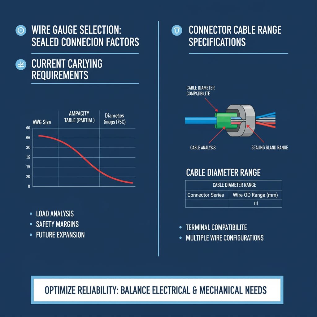
Current Carrying Capacity Requirements
Load Analysis: Calculate total current requirements including normal operating current, starting currents, and safety margins to prevent overheating and voltage drops2.
Ampacity Tables: Use NEC Ampacity Tables3 or international standards (IEC 60364) to determine minimum wire gauge based on continuous current ratings and installation conditions.
Safety Margins: Apply 80% derating factor for continuous loads and additional margins for critical applications where failure consequences are severe.
Future Expansion: Consider potential load increases during system lifecycle to avoid undersized wire selection that requires costly retrofits.
Connector Cable Range Specifications
Cable Diameter Compatibility: Match wire outer diameter (including insulation) to connector cable range specifications to ensure proper sealing and strain relief.
Sealing Gland Requirements: Verify that selected wire gauge fits within cable gland diameter ranges while maintaining compression sealing effectiveness.
Terminal Compatibility: Ensure wire gauge matches connector terminal specifications for proper crimping and electrical contact performance.
Multiple Wire Configurations: Consider overall bundle diameter when using multiple wires through single connector entry points.
Robert, a control systems engineer at a wind farm in Texas, experienced repeated failures in turbine control connectors despite using properly rated electrical components. The issue was wire gauge mismatch – 12 AWG wire in connectors designed for 14-16 AWG range created poor sealing that allowed moisture ingress during storms. We provided properly sized 14 AWG wire specifications and matching sealed connectors with correct cable ranges. The solution eliminated moisture-related failures, achieving 18 months of reliable operation and saving $85,000 in maintenance costs while ensuring turbine availability during peak wind seasons.
How Do You Calculate Current Carrying Requirements?
Accurate current calculations ensure wire gauge provides adequate capacity with appropriate safety margins. Current carrying requirements for sealed connector wire gauge selection involve calculating maximum continuous current, applying temperature derating factors, considering installation conditions, adding safety margins for load variations, and accounting for voltage drop limitations to ensure reliable electrical performance without overheating or power quality issues.
Maximum Current Calculation
Continuous Load Analysis: Identify all continuous loads that operate for 3+ hours and apply 125% safety factor as required by electrical codes.
Starting Current Considerations: Calculate inrush currents[^5] for motors, transformers, and capacitive loads that may exceed steady-state current by 5-8 times.
Diversity Factors: Apply appropriate diversity factors when multiple loads don’t operate simultaneously to avoid oversizing wire unnecessarily.
Load Growth Planning: Include 20-25% capacity margin for future load additions and system expansion requirements.
Temperature Derating Calculations
Ambient Temperature Effects: Apply derating factors based on ambient temperature – standard ampacity tables assume 30°C (86°F) ambient conditions.
Installation Method Impact: Consider derating for conduit installations, cable bundling, and enclosed spaces that reduce heat dissipation.
Insulation Temperature Ratings: Match wire insulation temperature rating (60°C, 75°C, 90°C) to application requirements and connector specifications.
Thermal Management: Account for additional heat sources near cable runs that may require further derating for safe operation.
| Wire Gauge (AWG) | 60°C Insulation | 75°C Insulation | 90°C Insulation | Typical Connector Range |
|---|---|---|---|---|
| 18 | 7A | 10A | 14A | 2-4mm |
| 16 | 10A | 13A | 18A | 3-5mm |
| 14 | 15A | 20A | 25A | 4-6mm |
| 12 | 20A | 25A | 30A | 5-8mm |
| 10 | 30A | 35A | 40A | 7-10mm |
What Are the Sealing Performance Considerations?
Proper sealing requires precise wire gauge matching to connector specifications for effective environmental protection. Sealing performance in sealed connectors depends on proper wire gauge selection that ensures adequate compression without over-compression, maintains cable range compatibility, prevents seal extrusion or damage, provides consistent sealing force distribution, and accommodates thermal expansion while preserving IP rating integrity throughout service life.

Cable Range Compatibility
Diameter Matching: Select wire gauge that falls within connector cable range specifications – typically specified as minimum and maximum outer diameter ranges.
Compression Zone Design: Understand how connector sealing systems work – O-ring seals, compression glands, or molded seals each have specific requirements.
Seal Material Compatibility: Verify that wire insulation materials are compatible with connector sealing materials to prevent chemical degradation.
Multiple Entry Considerations: When using multiple wires, ensure total bundle diameter doesn’t exceed connector capacity while maintaining individual wire sealing.
Sealing Force Distribution
Uniform Compression: Proper wire gauge ensures even compression around cable circumference, preventing leak paths from uneven sealing pressure.
Seal Durability: Correct compression prevents seal extrusion, cracking, or permanent deformation that compromises long-term sealing performance.
Thermal Cycling Resistance: Proper fit accommodates thermal expansion and contraction without losing sealing effectiveness during temperature changes.
Vibration Resistance: Adequate but not excessive compression maintains sealing under mechanical vibration and movement conditions.
IP Rating Maintenance
Ingress Protection Standards: Understand IP rating requirements – IP67 for temporary immersion, IP68 for continuous submersion, IP69K for high-pressure washing.
Test Condition Compliance: Ensure wire gauge selection supports connector’s ability to pass IP rating tests under specified pressure and duration conditions.
Long-term Performance: Consider seal aging, UV exposure, and chemical resistance when selecting wire gauge for long-term IP rating maintenance.
Installation Quality Impact: Proper wire gauge selection reduces installation errors that could compromise IP rating performance in field conditions.
How Do Environmental Conditions Affect Wire Gauge Selection?
Environmental factors significantly impact wire gauge requirements and connector performance in sealed applications. Environmental conditions affect wire gauge selection through temperature derating requirements, chemical resistance needs, UV exposure considerations, mechanical stress factors, moisture exposure levels, and vibration resistance requirements that may necessitate larger wire gauges or special insulation materials to maintain reliable performance.
Temperature Considerations
Operating Temperature Range: High temperatures reduce wire current capacity, requiring larger gauge selection to maintain safe operating conditions.
Thermal Cycling Effects: Repeated heating and cooling cycles stress wire insulation and connector seals, potentially requiring oversized selection for reliability.
Heat Source Proximity: Nearby heat sources like engines, transformers, or process equipment may require additional temperature derating factors.
Insulation Selection: Choose wire insulation rated for maximum expected temperature plus safety margin – THHN (90°C), XHHW (90°C), or specialized high-temperature types.
Chemical and UV Exposure
Insulation Compatibility: Select wire insulation materials resistant to chemicals present in the application environment – oils, solvents, acids, or cleaning agents.
UV Resistance Requirements: Outdoor applications require UV-resistant insulation materials or protective conduit to prevent insulation degradation.
Ozone Resistance: Industrial environments with ozone exposure require specialized insulation materials that resist ozone cracking and degradation.
Contamination Protection: Sealed connectors must maintain protection against specific contaminants present in the application environment.
Hiroshi, maintenance supervisor at a chemical processing plant in Osaka, Japan, struggled with frequent connector failures in wash-down areas despite using IP69K rated components. The problem was wire gauge selection that didn’t account for high-temperature steam cleaning (80°C) and aggressive cleaning chemicals. We specified larger wire gauge (12 AWG instead of 14 AWG) with chemical-resistant XLPE insulation and matching sealed connectors designed for the cable range. The solution eliminated failures during cleaning cycles, achieving 24 months of reliable operation and ensuring food safety compliance while reducing maintenance costs by 60%.
What Are Common Wire Gauge Selection Mistakes?
Understanding common mistakes helps engineers avoid costly failures and ensure reliable sealed connector performance. Common wire gauge selection mistakes include undersizing for current requirements, ignoring temperature derating factors, mismatching connector cable ranges, overlooking voltage drop calculations, neglecting environmental conditions, using incorrect ampacity tables, and failing to consider future load growth that leads to system failures and safety hazards.
Electrical Design Errors
Undersizing for Load: Using minimum code requirements without safety margins leads to overheating, voltage drops, and premature failure.
Ignoring Starting Currents: Failing to account for motor starting currents or inrush loads can cause nuisance tripping and voltage sags.
Voltage Drop Neglect: Not calculating voltage drop effects, especially in long cable runs, results in poor equipment performance and efficiency losses.
Wrong Ampacity Tables: Using incorrect ampacity tables for installation conditions leads to undersized wire selection and potential safety hazards.
Mechanical and Sealing Errors
Cable Range Mismatch: Selecting wire gauge outside connector cable range specifications compromises sealing effectiveness and IP rating performance.
Over-Compression Issues: Using wire too small for connector range causes seal over-compression, extrusion, and eventual seal failure.
Under-Compression Problems: Wire too large for connector range prevents adequate sealing compression, allowing water and contaminant ingress.
Bundle Diameter Oversight: Not considering total bundle diameter when using multiple wires through single connector entries.
Environmental Oversights
Temperature Derating Neglect: Failing to apply temperature derating factors for high ambient temperatures or enclosed installations.
Chemical Compatibility Issues: Not verifying wire insulation compatibility with environmental chemicals, cleaning agents, or process fluids.
UV Exposure Ignorance: Using non-UV resistant insulation in outdoor applications leads to premature insulation failure and safety hazards.
Vibration Considerations: Not accounting for mechanical stress and vibration that may require larger wire gauge for mechanical strength.
Conclusion
Selecting the correct wire gauge for sealed connectors requires systematic consideration of electrical requirements, mechanical compatibility, and environmental conditions to ensure reliable performance and long-term durability. Through proper current calculations, temperature derating, cable range matching, and environmental analysis, engineers can specify wire gauge that maintains both electrical performance and sealing integrity throughout the system lifecycle. At Bepto, we provide comprehensive technical support to help customers select optimal wire gauge and sealed connector combinations for their specific applications, ensuring reliable operation while minimizing installation complexity and long-term maintenance costs. Remember, the right wire gauge isn’t just about meeting electrical codes – it’s about creating a complete sealing system that protects your investment 😉
FAQs About Wire Gauge Selection
Q: How do I determine the minimum wire gauge for my sealed connector application?
A: Calculate maximum continuous current, apply 125% safety factor, check temperature derating requirements, and verify the result falls within your connector’s cable range specifications. Use NEC ampacity tables or IEC standards for baseline current capacity.
Q: What happens if I use wire gauge that’s too small for my sealed connector?
A: Too-small wire gauge causes overheating, voltage drops, and poor sealing due to over-compression of connector seals, leading to seal extrusion, water ingress, and potential electrical failures or safety hazards.
Q: Can I use larger wire gauge than calculated for sealed connectors?
A: Yes, but ensure the larger gauge still fits within the connector’s maximum cable range to maintain proper sealing compression. Oversizing provides safety margin but increases cost and installation complexity.
Q: How do temperature conditions affect wire gauge selection for sealed connectors?
A: High temperatures reduce wire current capacity, requiring larger gauge selection. Apply derating factors from ampacity tables – typically 88% at 40°C, 82% at 45°C, and 75% at 50°C ambient temperature.
Q: What’s the difference between wire gauge selection for indoor versus outdoor sealed connectors?
A: Outdoor applications require UV-resistant insulation, additional temperature derating for solar heating, and consideration of weather exposure effects. Indoor applications focus more on ambient temperature and ventilation conditions affecting current capacity.
-
Explore the causes of voltage drop in electrical circuits and learn the formulas used to calculate it for proper wire sizing in long cable runs. ↩
-
Learn how to use National Electrical Code (NEC) ampacity tables to determine the maximum current a conductor can safely carry under specific conditions. ↩
-
Investigate the phenomenon of inrush current, the instantaneous high input current drawn by a power supply or electrical equipment when first turned on. ↩
