

Circulating currents in armored cable systems can cause devastating equipment failures, cable overheating, and power losses that cost industrial facilities millions annually in unplanned downtime and energy waste. Insulated cable glands prevent circulating currents by providing electrical isolation between cable armor and equipment enclosures, using specialized insulation barriers that break the conductive path while maintaining mechanical strength and environmental sealing – these glands are essential for single-core armored cables, parallel cable runs, and high-current applications where circulating currents can exceed safe operating limits. Last year, Robert Mitchell, the electrical maintenance supervisor at a steel manufacturing plant in Birmingham, UK, was experiencing mysterious cable overheating issues that caused three production line shutdowns. After our technical team identified circulating current problems in their 11kV single-core cable installations, we provided XLPE-insulated cable glands that eliminated the issue completely, saving his facility over £450,000 in potential equipment damage and production losses.
Table of Contents
- What Are Circulating Currents and Why Do They Occur?
- How Do Insulated Cable Glands Prevent Circulating Currents?
- Which Applications Require Insulated Cable Glands?
- What Are the Key Design Features and Materials?
- How to Select and Install Insulated Cable Glands?
- FAQs About Insulated Cable Glands
What Are Circulating Currents and Why Do They Occur?
Understanding circulating current phenomena is crucial for electrical engineers working with armored cable systems, particularly in high-power industrial applications where these currents can cause significant operational problems.
Circulating currents are unwanted electrical currents that flow through cable armor and metallic sheaths when multiple parallel cables carry load current, creating closed loops through equipment enclosures and causing cable overheating, power losses, and potential equipment damage – these currents occur due to electromagnetic induction1 between parallel conductors and can reach dangerous levels in single-core armored cable installations.

The Physics Behind Circulating Currents
Electromagnetic Induction Principle: When AC current flows through parallel conductors, each cable creates a magnetic field that induces voltages in adjacent cables. In multi-core cables, these induced voltages typically cancel out, but single-core cables create unbalanced magnetic fields that induce significant voltages in nearby cable armor and metallic sheaths.
Current Path Formation: Without proper isolation, these induced voltages drive currents through the cable armor, equipment enclosures, and ground connections, creating closed loops. The magnitude of circulating currents depends on cable spacing, load current, frequency, and the impedance of the return path through armor and enclosures.
Power Loss Calculations: Circulating currents can reach 10-30% of the main load current in poorly designed installations. For a 1000A system, circulating currents of 100-300A through cable armor create substantial I²R losses2, generating heat that can exceed cable temperature ratings and cause insulation degradation.
Real-World Impact Assessment
Temperature Rise Effects: Our field measurements show that circulating currents can increase cable operating temperatures by 15-25°C above normal levels. This temperature rise significantly reduces cable life expectancy and can trigger thermal protection systems, causing unexpected shutdowns.
Energy Efficiency Impact: A typical 500kW motor installation with uncontrolled circulating currents can waste 15-50kW in armor losses alone. Over a year of continuous operation, this represents £25,000-£85,000 in unnecessary energy costs at current UK electricity rates.
Equipment Reliability Concerns: Circulating currents create electromagnetic interference, cause vibration in cable armor, and can lead to accelerated aging of cable insulation. These effects compound over time, increasing maintenance requirements and reducing overall system reliability.
How Do Insulated Cable Glands Prevent Circulating Currents?
Insulated cable glands employ specialized design features and materials to break the conductive path between cable armor and equipment enclosures while maintaining all other essential functions.
Insulated cable glands prevent circulating currents by incorporating electrical isolation barriers between the cable armor and gland body, using high-voltage insulation materials like XLPE or ceramic insulators that block current flow while maintaining mechanical strength, environmental sealing, and electromagnetic shielding properties required for industrial applications.
Isolation Barrier Technology
Insulation Material Selection: Our insulated glands use cross-linked polyethylene (XLPE) or ceramic insulation barriers rated for voltages up to 36kV. These materials provide excellent electrical isolation while maintaining mechanical strength to support cable weight and withstand installation stresses.
Barrier Design Configuration: The insulation barrier is positioned between the cable armor termination and the gland body, creating a complete electrical break in the conductive path. Special attention is paid to creepage distances and clearances to prevent flashover under high-voltage conditions.
Sealing Integration: The insulation barrier is integrated with the primary sealing system to maintain IP68 environmental protection. This dual-function design ensures that electrical isolation doesn’t compromise the gland’s ability to prevent moisture and contaminant ingress.
Current Interruption Mechanism
Path Isolation: By breaking the conductive connection between cable armor and equipment enclosure, insulated glands force circulating currents to find alternative paths with much higher impedance. This effectively reduces circulating currents to negligible levels, typically less than 1% of load current.
Electromagnetic Compatibility: The insulation barrier is designed to maintain electromagnetic shielding effectiveness while providing electrical isolation. This ensures that EMC performance isn’t compromised when preventing circulating currents.
Grounding Considerations: Insulated glands require careful attention to cable armor grounding. The armor must be grounded at one end only to prevent ground loops while maintaining safety earthing requirements.
Which Applications Require Insulated Cable Glands?
Specific electrical installations and operating conditions create situations where circulating currents become problematic, making insulated cable glands essential for safe and efficient operation.
Insulated cable glands are essential for single-core armored cables in parallel installations, high-current motor drives, power distribution systems above 1kV, long cable runs in industrial facilities, and any application where cable armor circulating currents exceed 5% of load current or cause measurable temperature rise in cable systems.
High-Current Motor Applications
Variable Frequency Drives: Large Variable Frequency Drives3 installations often use multiple parallel cables to handle high currents. The switching frequencies in VFDs can exacerbate circulating current problems, making insulated glands particularly important for these applications.
Synchronous Motor Installations: High-power synchronous motors in steel mills, cement plants, and mining operations typically require single-core cables due to current levels exceeding 1000A. These installations are prime candidates for insulated gland technology.
Pump and Compressor Systems: Large industrial pumps and compressors often operate continuously, making energy efficiency critical. Eliminating circulating current losses can provide significant operational cost savings over the equipment lifetime.
Power Distribution Systems
Medium Voltage Networks: Distribution systems operating at 6.6kV, 11kV, and 33kV commonly use single-core armored cables where circulating currents can be particularly problematic. Insulated glands are often specified as standard practice for these voltage levels.
Substation Connections: Cable connections to transformers, switchgear, and other substation equipment frequently require insulated glands to prevent circulating currents that could interfere with protection systems or cause measurement errors.
Industrial Plant Distribution: Large manufacturing facilities with extensive cable networks benefit from insulated glands to improve overall system efficiency and reduce electromagnetic interference between circuits.
Customer Success Story
Hassan Al-Rashid, the chief electrical engineer at a petrochemical complex in Dubai, UAE, faced a challenging situation with their new 15MW compressor installation. The original design used standard cable glands for the six parallel single-core 11kV cables, but commissioning tests revealed circulating currents of 180A causing dangerous cable heating. Our team provided custom-designed insulated cable glands with ceramic isolation barriers rated for the harsh desert environment. After installation, circulating currents dropped to less than 8A, cable temperatures normalized, and the system has operated flawlessly for over two years, saving an estimated $75,000 annually in energy costs while eliminating safety concerns.
What Are the Key Design Features and Materials?
Insulated cable glands require specialized engineering to balance electrical isolation requirements with mechanical strength, environmental protection, and installation practicality.
Key design features include high-voltage insulation barriers made from XLPE or ceramic materials, integrated sealing systems maintaining IP68 protection, mechanical support structures handling cable weight and stress, electromagnetic shielding preservation, and specialized grounding provisions that allow proper armor earthing while preventing circulating current formation.
Insulation System Design
Material Selection Criteria: We select insulation materials based on voltage rating, temperature capability, chemical resistance, and long-term stability. XLPE4 provides excellent performance up to 36kV with superior aging characteristics, while ceramic insulators offer higher temperature capability for extreme environments.
Voltage Rating Standards: Our insulated glands are designed and tested according to IEC 60502 and IEEE 404 standards, with voltage ratings from 1kV to 36kV. Impulse voltage tests ensure reliable performance under transient conditions common in industrial power systems.
Creepage and Clearance Design: Insulation barriers incorporate adequate creepage distances to prevent surface tracking and sufficient clearances to avoid flashover. These dimensions are calculated according to IEC 60664 standards for the specific pollution degree and installation environment.
Mechanical Construction Features
Load Distribution: The gland body is designed to transfer cable weight and pulling forces around the insulation barrier without compromising electrical isolation. Special attention is paid to stress concentration points that could cause insulation failure.
Armor Termination: Cable armor termination is designed to provide secure mechanical connection while maintaining electrical isolation from the gland body. This often involves specialized clamping systems that distribute forces evenly.
Sealing Integration: Multiple sealing barriers ensure environmental protection isn’t compromised by the insulation requirements. Primary seals prevent moisture ingress while secondary seals provide backup protection.
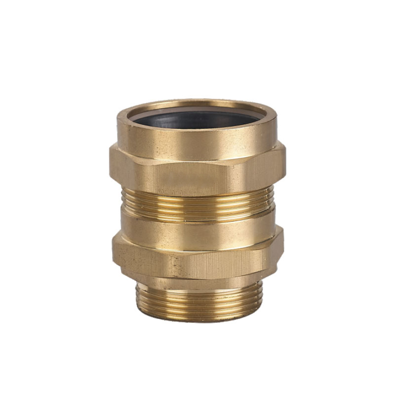
Material Specifications
| Component | Material Options | Key Properties |
|---|---|---|
| Insulation Barrier | XLPE, Ceramic, PTFE | High dielectric strength, thermal stability |
| Gland Body | Brass, Stainless Steel 316L | Corrosion resistance, mechanical strength |
| Sealing Elements | NBR, EPDM, Viton | Chemical compatibility, temperature range |
| Hardware | Stainless Steel 316 | Corrosion resistance, mechanical properties |
How to Select and Install Insulated Cable Glands?
Proper selection and installation of insulated cable glands requires careful consideration of electrical parameters, environmental conditions, and installation constraints to ensure optimal performance.
Selection criteria include cable voltage rating, armor type and size, environmental conditions, current levels, and specific application requirements, while installation requires proper cable preparation, armor grounding arrangements, torque specifications, and electrical testing to verify isolation effectiveness and ensure long-term reliability.
Selection Parameters
Electrical Requirements: Determine the system voltage, fault current levels, and expected circulating current magnitude. This information drives the insulation barrier voltage rating and mechanical design requirements.
Cable Specifications: Cable armor type (steel wire, steel tape, aluminum), outer diameter, and armor termination requirements affect gland selection. Single-core cables typically require different solutions than multi-core cables.
Environmental Factors: Operating temperature range, chemical exposure, moisture conditions, and mechanical vibration levels influence material selection and design features.
Installation Best Practices
Cable Preparation: Proper cable preparation is critical for insulated gland performance. Armor must be cut to precise lengths, and cable cores must be properly supported to prevent stress on the insulation barrier.
Grounding Strategy: Cable armor should be grounded at one end only to prevent ground loops while maintaining safety earthing. The grounding connection must be made before the insulation barrier to ensure proper operation.
Torque Specifications: Follow manufacturer torque specifications carefully to ensure proper sealing without over-stressing the insulation barrier. Use calibrated torque tools and apply torque in the specified sequence.
Testing and Commissioning: After installation, perform insulation resistance tests to verify barrier integrity and measure circulating currents to confirm effective isolation. Document baseline measurements for future reference.
Installation Quality Control
Visual Inspection: Check for proper cable preparation, correct component assembly, and absence of contamination on insulation surfaces. Any damage to insulation barriers must be addressed before energizing.
Electrical Testing: Perform high-voltage insulation tests according to manufacturer specifications. Typical test voltages are 2.5 times rated voltage for 1 minute, with insulation resistance measurements exceeding 1000 MΩ.
Performance Verification: Measure circulating currents after installation to verify effective isolation. Properly installed insulated glands should reduce circulating currents to less than 1% of load current.
Conclusion
Insulated cable glands represent a critical technology for preventing circulating currents in modern electrical installations, particularly where single-core armored cables and high-current applications create conditions for significant energy losses and equipment damage. The key to success lies in understanding when circulating currents become problematic, selecting appropriate insulation technology for specific applications, and ensuring proper installation practices that maintain both electrical isolation and environmental protection. At Bepto, we’ve developed comprehensive solutions ranging from standard XLPE-insulated glands for typical industrial applications to specialized ceramic-barrier designs for extreme environments and high-voltage systems. Our decade of experience in cable gland technology, combined with full ATEX, IECEx, and UL certifications, ensures that our insulated glands meet the most demanding performance requirements while providing the cost-effective solutions our customers need. Whether you’re dealing with circulating current problems in existing installations or designing new systems to prevent these issues, our technical team can help you select and implement the right insulated gland solution for your specific requirements. 😉
FAQs About Insulated Cable Glands
Q: How do I know if my installation needs insulated cable glands?
A: You need insulated cable glands if you have single-core armored cables in parallel, circulating currents exceeding 5% of load current, or measurable cable temperature rise due to armor currents. Thermal imaging and current measurements can identify these conditions in existing installations.
Q: What’s the difference between insulated and standard cable glands?
A: Insulated cable glands include electrical isolation barriers between cable armor and gland body to prevent circulating currents, while standard glands provide direct electrical connection. Insulated versions maintain the same sealing and mechanical properties but add current isolation functionality.
Q: Can insulated cable glands be used in hazardous areas?
A: Yes, our insulated cable glands are available with ATEX and IECEx certifications for hazardous area applications. The insulation barrier design maintains flameproof and increased safety properties required for explosive atmosphere installations.
Q: How much do insulated cable glands cost compared to standard ones?
A: Insulated cable glands typically cost 40-60% more than standard versions, but the energy savings from eliminating circulating currents often provide payback within 1-2 years for high-current applications. The prevention of cable damage and equipment failures provides additional value.
Q: Do insulated cable glands require special installation procedures?
A: Installation is similar to standard glands but requires attention to armor grounding arrangements and electrical testing to verify isolation effectiveness. Proper torque application is critical to avoid damaging the insulation barrier while maintaining environmental sealing.
-
Learn about the physics principle of electromagnetic induction and how it creates induced voltages. ↩
-
Understand the concept of I²R (Joule) losses and how they generate heat and waste energy in conductors. ↩
-
Explore what Variable Frequency Drives (VFDs) are and how they are used to control electric motors. ↩
-
Read about the material properties and advantages of cross-linked polyethylene (XLPE) as an electrical insulator. ↩
