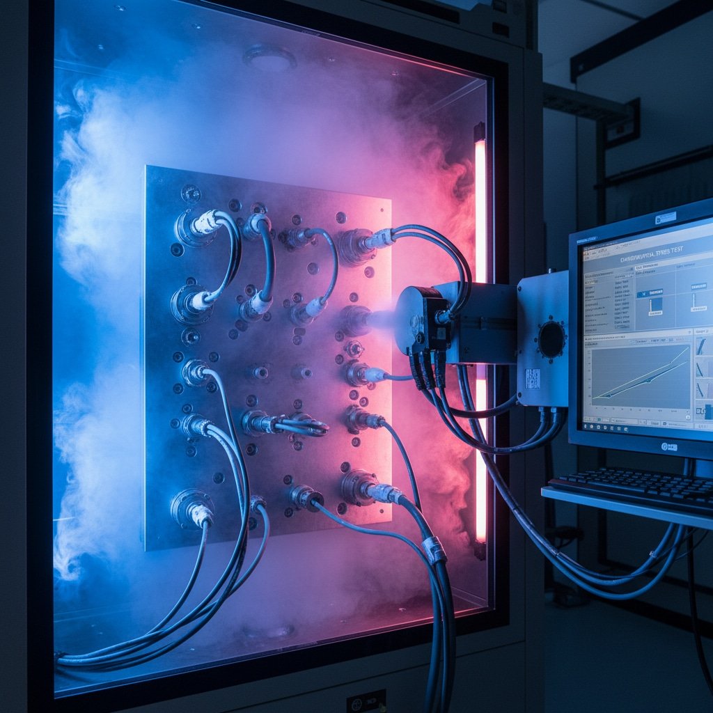
Selecting the wrong cable gland for instrumentation and control cables can lead to signal interference, moisture ingress, and costly system failures. Many engineers struggle with the complex requirements of different cable types, environmental conditions, and performance specifications that affect critical control systems.
Proper gland selection for instrumentation and control cables requires understanding cable characteristics, environmental conditions, EMC requirements1, and certification standards to ensure reliable signal transmission and system protection. The right choice prevents interference, maintains signal integrity, and protects sensitive equipment from environmental hazards.
Last month, I received an urgent call from Marcus, a control systems engineer at a pharmaceutical manufacturing facility in Frankfurt, Germany. Their new production line was experiencing intermittent signal failures that threatened FDA compliance. After investigating, we discovered that standard cable glands without EMC shielding were allowing electromagnetic interference to disrupt their precision control signals. This situation perfectly illustrates why specialized gland selection is crucial for instrumentation applications.
Table of Contents
- What Makes Instrumentation Cable Glands Different?
- How Do Environmental Factors Affect Gland Selection?
- What Are the Key EMC and Shielding Requirements?
- How to Choose the Right Gland Size and Thread Type?
- FAQs About Instrumentation Cable Gland Selection
What Makes Instrumentation Cable Glands Different?
Understanding the unique requirements of instrumentation cables helps identify the specific gland features needed for optimal performance.
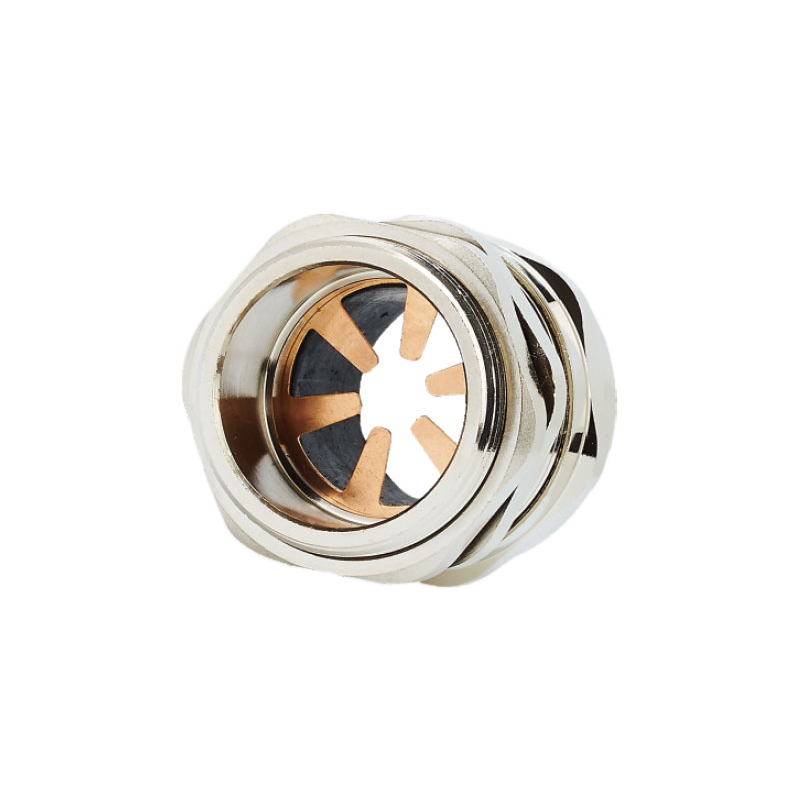
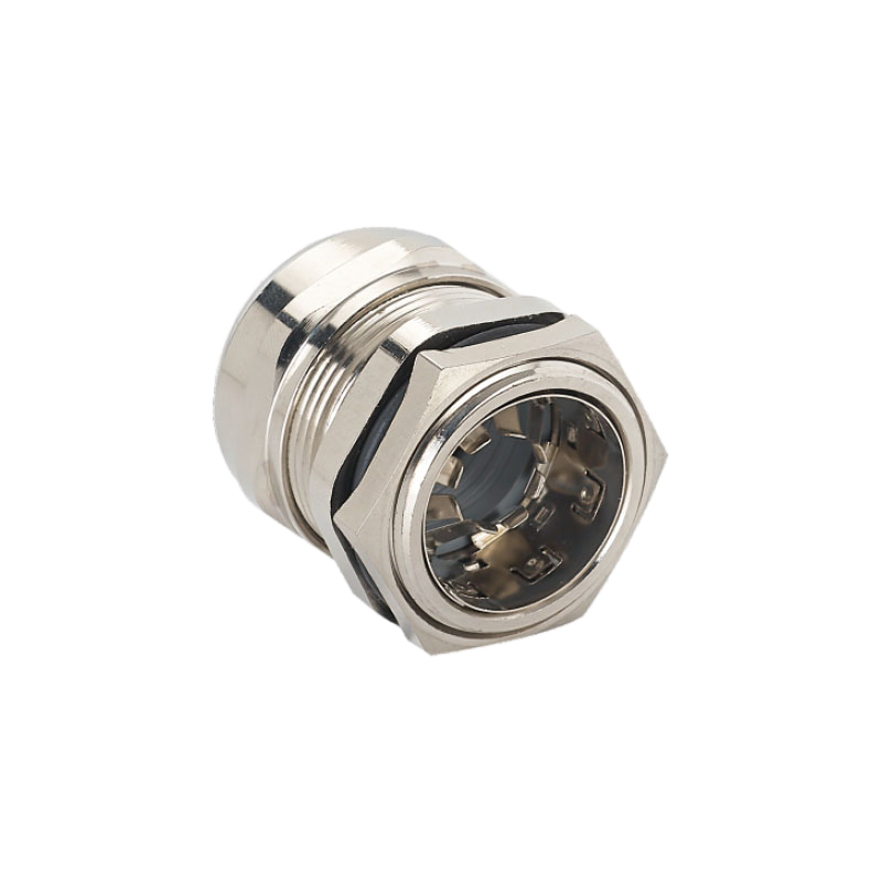
Instrumentation cable glands differ from standard power cable glands by providing EMC shielding, maintaining cable screen continuity, offering precise sealing for smaller cables, and ensuring signal integrity protection. These specialized features are essential for sensitive control and measurement applications.
Cable Construction Considerations
Instrumentation cables typically feature multiple conductors, individual or overall screening, and specialized insulation materials. Unlike power cables, they carry low-voltage signals that are highly susceptible to electromagnetic interference. The cable gland must accommodate these construction differences while maintaining electrical continuity of the screening system.
Screen Continuity Requirements: The cable screen or shield must maintain 360-degree electrical continuity through the gland to provide effective EMC protection. This requires specialized clamping mechanisms that ensure reliable contact between the cable screen and the gland body, which then connects to the equipment enclosure.
Multiple Cable Accommodation: Many instrumentation applications require multiple small-diameter cables to enter through a single gland. Multi-cable glands with individual sealing elements for each cable provide space efficiency while maintaining IP ratings and EMC performance.
Signal Integrity Protection
Instrumentation signals are typically 4-20mA current loops2, digital communications, or low-voltage analog signals that require protection from external interference. The gland selection directly impacts signal quality and system reliability.
EMC Performance Standards: Instrumentation cable glands must meet specific EMC standards like EN 50206 or IEC 624443, providing measurable shielding effectiveness across relevant frequency ranges. At Bepto, our EMC cable glands achieve >60dB shielding effectiveness from 10MHz to 1GHz, ensuring reliable protection for sensitive control signals.
Material and Construction Quality
The precision required for instrumentation applications demands higher manufacturing tolerances and material quality compared to standard cable glands. Sealing elements must provide consistent compression, and metallic components require excellent conductivity for EMC performance.
Corrosion Resistance: Instrumentation installations often operate in challenging environments where corrosion can compromise both sealing and electrical performance. Stainless steel 316L construction with appropriate surface treatments ensures long-term reliability in chemical processing, marine, and outdoor applications.
How Do Environmental Factors Affect Gland Selection?
Environmental conditions significantly impact gland material selection, sealing requirements, and long-term performance in instrumentation applications.
Environmental factors affecting instrumentation gland selection include temperature extremes, chemical exposure, moisture levels, vibration, and atmospheric conditions that can compromise sealing integrity and EMC performance. Proper environmental assessment ensures reliable operation throughout the system lifecycle.

Temperature and Thermal Cycling
Instrumentation systems often operate across wide temperature ranges, from outdoor installations experiencing -40°C winters to process equipment reaching +150°C. The gland materials and sealing elements must maintain performance across these extremes.
Sealing Material Selection: EPDM seals perform well from -40°C to +150°C, while specialized fluoroelastomers extend the range to +200°C. For extreme low-temperature applications, silicone seals maintain flexibility down to -55°C. The thermal expansion coefficients4 of different materials must be considered to prevent seal failure during thermal cycling.
Metal Expansion Considerations: Different metals expand at different rates, potentially creating gaps that compromise both sealing and EMC performance. Our engineering team carefully selects material combinations that minimize thermal stress while maintaining electrical continuity.
Chemical Compatibility
Process industries expose instrumentation glands to various chemicals that can degrade sealing materials or corrode metallic components. A comprehensive chemical compatibility assessment is essential for reliable operation.
I remember working with Ahmed, a project manager at a petrochemical complex in Dubai, UAE, who needed cable glands for a new sulfur recovery unit. The environment included hydrogen sulfide, sulfur dioxide, and various hydrocarbons at elevated temperatures. We specified stainless steel 316L glands with Viton seals and specialized coatings to ensure 20-year service life in this aggressive environment.
Chemical Resistance Testing: Material selection should be based on actual chemical compatibility testing rather than general guidelines. We maintain an extensive database of chemical resistance data for different seal materials and metallic finishes, enabling precise material selection for specific applications.
Vibration and Mechanical Stress
Instrumentation equipment often experiences vibration from nearby machinery, wind loading, or process-induced movement. The cable gland must maintain sealing integrity and electrical continuity under these dynamic conditions.
Anti-Vibration Features: Specialized gland designs include locking mechanisms that prevent loosening under vibration, reinforced cable strain relief to prevent conductor fatigue, and flexible sealing systems that accommodate movement without compromising performance.
What Are the Key EMC and Shielding Requirements?
EMC performance is often the most critical factor in instrumentation cable gland selection, directly affecting system reliability and regulatory compliance.
Key EMC requirements for instrumentation cable glands include 360-degree screen continuity, specified shielding effectiveness levels, low transfer impedance, and compliance with relevant EMC standards for the application environment. Proper EMC design prevents interference that can cause measurement errors or control system malfunctions.
Shielding Effectiveness Standards
Different applications require specific levels of EMC performance based on the sensitivity of the instrumentation and the electromagnetic environment. Industrial environments typically require 40-60dB shielding effectiveness, while sensitive laboratory or medical applications may need >80dB performance.
Frequency Range Considerations: EMC performance must be evaluated across the relevant frequency spectrum. Low-frequency interference (50Hz-1kHz) affects analog signals differently than high-frequency digital interference (1MHz-1GHz). Our EMC glands provide consistent performance across the full spectrum, ensuring protection for both analog and digital instrumentation.
Transfer Impedance Requirements: For critical applications, transfer impedance specifications define the maximum allowable impedance between the cable screen and the gland body. Values below 1mΩ at DC ensure effective screen continuity for sensitive measurements.
Screen Termination Methods
The method of terminating the cable screen at the gland significantly affects EMC performance and long-term reliability.
360-Degree Clamping: The most effective screen termination uses a conductive clamping ring that provides uniform contact around the entire cable circumference. This method ensures consistent EMC performance and prevents the formation of “pigtail” inductances that can compromise high-frequency shielding.
Conductive Gaskets: Some applications benefit from conductive gaskets between the gland and equipment enclosure to ensure optimal electrical continuity. These gaskets accommodate surface irregularities and prevent corrosion from affecting EMC performance.
EMC Testing and Verification
Proper EMC performance requires testing and verification according to relevant standards. This includes both type testing during product development and routine verification during installation.
Field Testing Methods: Simple continuity testing can verify basic screen continuity, while more sophisticated transfer impedance measurements provide quantitative EMC performance data. We provide detailed testing procedures and acceptance criteria for our EMC cable glands to ensure proper installation and performance verification.
How to Choose the Right Gland Size and Thread Type?
Proper sizing and thread selection ensure secure installation, optimal sealing performance, and compatibility with existing equipment.
Choosing the right gland size and thread type requires measuring cable outer diameter, determining equipment thread specifications, considering cable bend radius requirements, and allowing for future cable additions or modifications. Accurate sizing prevents installation problems and ensures long-term reliability.
Cable Diameter Measurement
Accurate cable diameter measurement is essential for proper gland selection, especially with instrumentation cables that may have irregular cross-sections due to screening or armoring.
Measurement Techniques: Use calipers to measure the cable at multiple points, as instrumentation cables may not be perfectly round. For screened cables, measure over the outer sheath, not the screen itself. Consider any cable markers or printing that might affect the effective diameter.
Size Selection Guidelines: Select a gland with a sealing range that accommodates the measured cable diameter with appropriate compression. Typically, the cable should fall within the middle 60% of the gland’s sealing range for optimal performance. Over-compression can damage cable insulation, while under-compression compromises sealing integrity.
Thread Type and Equipment Compatibility
Thread compatibility between the gland and equipment enclosure is crucial for proper installation and performance.
Common Thread Types: Instrumentation applications commonly use metric threads (M12, M16, M20, M25), NPT threads (1/2″, 3/4″, 1″), or specialized threads like PG or BSP. Verify the exact thread specification from equipment documentation, as visual identification can be unreliable.
Thread Engagement Requirements: Ensure adequate thread engagement for the application environment. High-vibration or high-pressure applications may require additional thread engagement or thread-locking compounds to prevent loosening.
Installation Space Considerations
Consider the space available for gland installation, including access for installation tools and future maintenance requirements.
Bend Radius Requirements: Instrumentation cables often have minimum bend radius specifications that must be maintained to prevent signal degradation. Ensure adequate space around the gland for proper cable routing without exceeding bend radius limits.
Multi-Cable Applications: When multiple cables enter through individual glands, consider the spacing requirements and potential for electromagnetic coupling between adjacent cables. Proper spacing and routing can minimize crosstalk and interference.
At Bepto, we provide comprehensive sizing guides and technical support to help customers select the optimal gland configuration for their specific instrumentation applications. Our engineering team can review cable specifications and installation requirements to recommend the most suitable products from our extensive range of EMC and instrumentation cable glands.
Conclusion
Selecting the right cable gland for instrumentation and control applications requires careful consideration of cable characteristics, environmental conditions, EMC requirements, and installation constraints. The specialized nature of instrumentation signals demands glands that provide superior EMC performance, precise sealing, and long-term reliability. Environmental factors like temperature, chemicals, and vibration significantly impact material selection and design requirements. EMC performance, including shielding effectiveness and screen continuity, is often the most critical factor for sensitive control systems. Proper sizing and thread selection ensure secure installation and optimal performance. At Bepto, our decade of experience in instrumentation cable gland manufacturing, combined with our comprehensive testing capabilities and quality certifications, enables us to provide reliable solutions for even the most demanding control system applications. Whether you need standard EMC glands or custom solutions for unique requirements, proper selection and installation ensure signal integrity and system reliability for years of trouble-free operation. 😉
FAQs About Instrumentation Cable Gland Selection
Q: What’s the difference between EMC cable glands and regular cable glands for instrumentation?
A: EMC cable glands provide electromagnetic shielding and maintain cable screen continuity, while regular glands only offer basic sealing. EMC versions include conductive clamping systems and achieve specific shielding effectiveness levels (typically 40-80dB) essential for protecting sensitive instrumentation signals from interference.
Q: How do I determine the right cable gland size for my instrumentation cable?
A: Measure the cable outer diameter with calipers at multiple points, then select a gland with a sealing range where your cable falls in the middle 60% of the range. For screened cables, measure over the outer sheath, and consider any cable markings that affect effective diameter.
Q: Can I use one cable gland for multiple instrumentation cables?
A: Yes, multi-cable glands are available with individual sealing elements for each cable. These maintain IP ratings and EMC performance while saving panel space. Ensure each cable diameter falls within the sealing range and consider potential electromagnetic coupling between adjacent cables.
Q: What thread type should I choose for instrumentation cable glands?
A: Thread selection depends on your equipment specifications. Common types include metric (M12, M16, M20, M25), NPT (1/2″, 3/4″, 1″), and PG threads. Always verify the exact thread specification from equipment documentation rather than visual identification to ensure proper fit and sealing.
Q: How important is EMC shielding effectiveness for instrumentation applications?
A: EMC shielding effectiveness is critical for instrumentation applications, typically requiring 40-60dB for industrial environments and >80dB for sensitive applications. Poor EMC performance can cause measurement errors, signal interference, and control system malfunctions, making proper EMC gland selection essential for reliable operation.
-
Understand what Electromagnetic Compatibility (EMC) is and why it’s critical for electronic systems. ↩
-
An explanation of the 4-20mA current loop standard used in industrial control systems. ↩
-
Access the official overview of the IEC 62444 standard for industrial cable glands. ↩
-
Explore the engineering concept of thermal expansion and how it’s calculated for different materials. ↩


