مقدمة
Think all cable gland insulating materials are created equal? One electrical breakdown at high voltage can cost millions in downtime and equipment damage. The dielectric strength of insulating materials determines how much electrical stress they can withstand before catastrophic failure, making this property critical for power distribution, industrial automation, and hazardous area applications.
قوة العزل الكهربائي1 of cable gland insulating materials varies dramatically, ranging from 15-25 kV/mm for standard nylon to over 40 kV/mm for specialized fluoropolymers, with material selection directly impacting system safety, voltage ratings, and long-term reliability in electrical installations. Understanding these differences is essential for proper material selection and avoiding costly electrical failures.
Last month, Marcus, an electrical engineer at a solar farm in Arizona, contacted us after experiencing repeated insulation failures in their DC combiner boxes. The standard nylon cable glands they were using couldn’t handle the high DC voltages and desert temperature extremes, leading to tracking2, carbonization, and eventual system shutdowns. This kind of dielectric failure can cascade through entire electrical systems, which is why we’ve developed comprehensive testing protocols for all our insulating materials across various voltage and environmental conditions.
جدول المحتويات
- What Determines Dielectric Strength in Cable Gland Materials?
- How Do Different Polymer Materials Compare for Electrical Performance?
- What Environmental Factors Affect Insulation Performance Over Time?
- How Are Dielectric Properties Tested and Certified for Cable Glands?
- What Are the Critical Applications Requiring High Dielectric Strength?
- الخاتمة
- FAQs About Cable Gland Dielectric Strength
What Determines Dielectric Strength in Cable Gland Materials?
Dielectric strength in cable gland materials is determined by molecular structure, material purity, processing conditions, crystallinity levels, and the presence of polar groups, with these factors collectively defining the material’s ability to resist electrical breakdown under high voltage stress.
The science behind dielectric strength involves understanding how electrical fields interact with polymer chains and how electrons move through insulating materials.
Molecular Structure Impact
Polymer Chain Architecture:
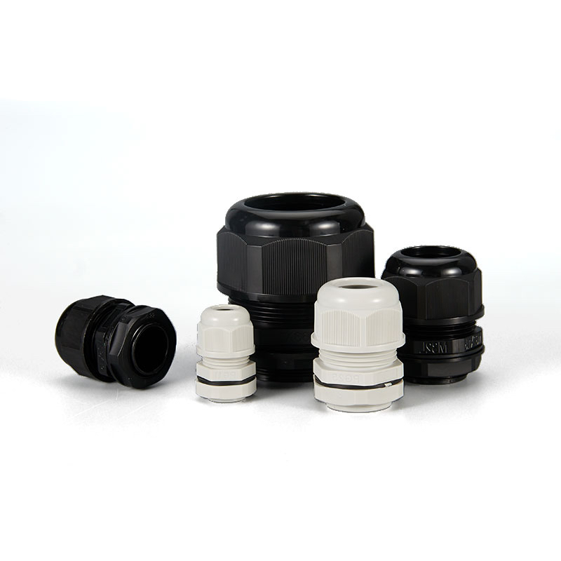
The arrangement of polymer chains directly affects dielectric performance. Linear chains with minimal branching typically provide better insulation properties than highly branched structures. Our nylon cable glands use carefully selected polymer grades with optimized chain architecture for maximum dielectric strength.
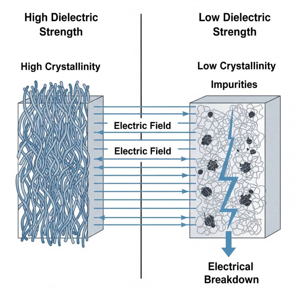
Crystallinity Effects:
Crystalline regions in polymers generally exhibit higher dielectric strength than amorphous regions. The degree of crystallinity can be controlled during processing to optimize electrical performance:
- High crystallinity: Better dielectric strength but reduced flexibility
- Low crystallinity: More flexible but potentially lower breakdown voltage
- Balanced crystallinity: Optimal compromise for cable gland applications
Material Purity and Processing
Impurity Control:
Even trace amounts of conductive impurities can dramatically reduce dielectric strength. Our manufacturing process includes:
- Raw material purification
- Clean room processing environments
- Contamination monitoring throughout production
- Final product electrical testing
Processing Temperature Effects:
Excessive processing temperatures can degrade polymer chains, reducing dielectric strength. We maintain precise temperature control during injection molding to preserve material properties.
Fundamental Electrical Properties
The key electrical properties that determine dielectric performance include:
| الممتلكات | التأثير على الأداء | Typical Values |
|---|---|---|
| قوة العزل الكهربائي | Breakdown voltage capability | 15-45 kV/mm |
| مقاوماتية الحجم3 | Leakage current resistance | 10¹²-10¹⁶ Ω⋅cm |
| Dielectric Constant | Field distribution | 2.5-4.5 |
| Dissipation Factor | Energy loss | 0.001-0.05 |
Hassan, who manages electrical installations across several petrochemical facilities in Kuwait, learned the importance of these properties when standard cable glands failed during routine high-voltage testing. We worked together to specify high-performance materials with verified dielectric properties, ensuring his installations meet the strictest electrical safety standards.
How Do Different Polymer Materials Compare for Electrical Performance?
Different polymer materials exhibit vastly different electrical performance characteristics, with fluoropolymers like PTFE offering the highest dielectric strength (40+ kV/mm), followed by specialized nylons (20-30 kV/mm), while standard thermoplastics typically provide 15-25 kV/mm depending on formulation and processing.
مواد عالية الأداء
Fluoropolymers (PTFE, FEP, PFA):
These materials represent the gold standard for electrical insulation:
- Dielectric strength: 40-60 kV/mm
- مقاومة ممتازة للمواد الكيميائية
- Wide temperature range (-200°C to +260°C)
- Virtually zero moisture absorption
- Superior long-term stability
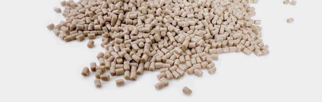
Specialized Engineering Plastics:
Advanced formulations designed for electrical applications:
- Modified nylons: 25-35 kV/mm
- Polyphenylene oxide (PPO): 30-40 kV/mm
- Polyetherimide (PEI): 25-30 kV/mm
- Excellent mechanical properties combined with electrical performance
Standard Industrial Materials
Nylon 6/6 and Nylon 12:
Our most common cable gland materials offer good electrical performance:
- Standard grades: 15-20 kV/mm
- Glass-filled grades: 18-25 kV/mm
- Flame-retardant grades: 12-18 kV/mm
- Cost-effective for most applications
Polypropylene and Polyethylene:
Lower-cost options for specific applications:
- Polypropylene: 20-25 kV/mm
- HDPE: 18-22 kV/mm
- مقاومة جيدة للمواد الكيميائية
- Limited temperature range
معايير اختيار المواد
متطلبات تصنيف الجهد الكهربائي:
- Low voltage (<1kV): Standard nylon adequate
- Medium voltage (1-35kV): Enhanced nylon or engineering plastics
- High voltage (>35kV): Fluoropolymers or specialized compounds
الاعتبارات البيئية:
- Indoor applications: Standard materials often sufficient
- Outdoor applications: UV-stabilized materials required
- Chemical exposure: Fluoropolymers preferred
- High temperature: Heat-stabilized formulations needed
Performance vs. Cost Analysis
| Material Category | التكلفة النسبية | قوة العزل الكهربائي | أفضل التطبيقات |
|---|---|---|---|
| نايلون قياسي | 1x | 15-20 kV/mm | صناعي عام |
| النايلون المحسّن | 1.5x | 20-30 kV/mm | Medium voltage |
| اللدائن الهندسية | 3-5x | 25-40 kV/mm | High performance |
| Fluoropolymers | 8-15x | 40-60 kV/mm | التطبيقات الحرجة |
Marcus from the Arizona solar farm discovered that investing in higher-grade materials actually reduced his total cost of ownership. While the initial material cost was 3x higher, the elimination of failures and maintenance more than justified the investment over the system’s 25-year lifespan.
What Environmental Factors Affect Insulation Performance Over Time?
Environmental factors including temperature cycling, UV exposure, moisture absorption, chemical contamination, and mechanical stress significantly degrade insulation performance over time, with dielectric strength potentially decreasing by 20-50% depending on material type and exposure conditions.

Temperature Effects on Dielectric Performance
الشيخوخة الحرارية:
Elevated temperatures accelerate polymer chain degradation:
- Chain scission reduces molecular weight
- Oxidation creates conductive pathways
- Crystallinity changes affect electrical properties
- Thermal expansion creates mechanical stress
تأثير تدوير درجة الحرارة:
Repeated heating and cooling cycles cause:
- Differential expansion stress
- Micro-crack formation
- Interface delamination
- تأثيرات الشيخوخة المتسارعة
Our testing shows that dielectric strength typically decreases by 2-5% per 10°C temperature increase, with the exact relationship depending on material type and time at temperature.
Moisture and Humidity Effects
Water Absorption Mechanisms:
Different materials exhibit varying susceptibility to moisture:
- Nylon: 2-8% water absorption (significant impact)
- Fluoropolymers: <0.01% (minimal impact)
- Engineering plastics: 0.1-2% (moderate impact)
Electrical Impact of Moisture:
Water absorption affects electrical properties through:
- Reduced volume resistivity
- Increased dielectric losses
- Lower breakdown voltage
- Enhanced tracking susceptibility
UV and Radiation Exposure
آليات التحلل الضوئي:
UV radiation breaks polymer chains and creates:
- Free radicals that propagate damage
- Carbonyl groups that reduce insulation
- Surface chalking and cracking
- تغيرات اللون التي تشير إلى التدهور
استراتيجيات التخفيف من الآثار:
- UV stabilizers in material formulation
- Carbon black pigmentation for outdoor use
- Protective coatings where applicable
- Regular inspection and replacement schedules
تأثير البيئة الكيميائية
Aggressive Chemical Exposure:
Industrial environments often contain chemicals that attack insulating materials:
- Acids: Cause hydrolysis in susceptible polymers
- Bases: Attack ester linkages
- Solvents: Cause swelling and plasticization
- Oils: Penetrate and reduce electrical properties
Material Compatibility Assessment:
We maintain extensive chemical compatibility databases for all our materials, helping customers select appropriate grades for specific environments.
Long-Term Performance Prediction
Accelerated Aging Testing:
We use standardized test methods to predict long-term performance:
- Thermal aging per ASTM D3045
- UV exposure per ASTM G154
- Humidity testing per ASTM D2565
- Combined stress testing for realistic conditions
Service Life Estimation:
Based on our testing, typical service life expectations are:
- Standard nylon: 10-15 years (indoor), 5-8 years (outdoor)
- Enhanced nylon: 15-20 years (indoor), 8-12 years (outdoor)
- Engineering plastics: 20-25 years (indoor), 12-18 years (outdoor)
- Fluoropolymers: 25+ years in most environments
How Are Dielectric Properties Tested and Certified for Cable Glands?
Dielectric properties of cable glands are tested using standardized methods including ASTM D1494 for dielectric strength, IEC 60695 for tracking resistance, and UL 746A for electrical performance, with testing conducted at various temperatures, humidity levels, and voltage stress conditions to ensure reliable performance.
طرق الاختبار القياسية
ASTM D149 – Dielectric Breakdown Voltage:
This fundamental test measures the voltage at which electrical breakdown occurs:
- Short-time tests: Rapid voltage increase to failure
- Step-by-step tests: Gradual voltage increases
- Slow-rate-of-rise tests: Extended time at each voltage level
- Results reported in kV/mm for material comparison
IEC 60112 – Comparative Tracking Index (CTI):
Measures resistance to tracking under wet conditions:
- Electrolyte solution applied to surface
- Electrical stress applied between electrodes
- Time to tracking failure recorded
- Critical for outdoor and humid applications
UL 746A – Electrical Performance:
Comprehensive evaluation including:
- Dielectric strength at various temperatures
- Arc resistance measurements
- High-current arc ignition testing
- Long-term electrical aging studies
قدراتنا الاختبارية في Bepto
In-House Testing Laboratory:
We’ve invested in comprehensive electrical testing equipment:
- High-voltage AC/DC test sets up to 100kV
- Environmental chambers (-40°C to +200°C, 95% RH)
- Tracking and erosion test equipment
- أنظمة الحصول على البيانات الآلية
اختبار مراقبة الجودة:
تخضع كل دفعة إنتاج لـ
- التحقق من قوة العزل الكهربائي
- Volume resistivity measurement
- Comparative tracking index testing
- الفحص البصري للعيوب
متطلبات التصديق
International Standards Compliance:
Our cable glands meet various international electrical standards:
- IEC 62444: Cable glands for electrical installations
- UL 514B: Conduit, tubing, and cable fittings
- CSA C22.2 No. 18: Outlet boxes, fittings, and covers
- ATEX/IECEx: Explosion-proof electrical equipment
وثائق الاختبار:
We provide comprehensive test reports including:
- Material certificates with electrical properties
- Production lot testing results
- Long-term aging study data
- Application-specific performance validation
Environmental Testing Protocols
اختبار الإجهاد المشترك:
تنطوي ظروف العالم الحقيقي على ضغوطات متعددة ومتزامنة:
- Temperature + humidity + electrical stress
- UV exposure + thermal cycling + voltage
- Chemical exposure + mechanical stress + electrical field
- Vibration + temperature + high voltage
اختبار العمر الافتراضي المعجل:
We use elevated stress conditions to predict long-term performance:
- نمذجة أرهينيوس لتأثيرات درجة الحرارة
- Peck’s model for humidity acceleration
- نموذج إيرينج لعوامل الإجهاد المتعددة
- Statistical analysis for confidence intervals
Hassan’s facilities now require comprehensive electrical testing documentation for all cable glands, following several industry incidents involving electrical failures. Our detailed test reports and certification packages have helped his procurement team make informed decisions while meeting stringent safety requirements.
What Are the Critical Applications Requiring High Dielectric Strength?
Critical applications requiring high dielectric strength cable glands include power generation and distribution systems, renewable energy installations, industrial motor control centers, hazardous area electrical equipment, and high-voltage testing facilities where electrical breakdown can cause catastrophic failures, safety hazards, and expensive downtime.
Power Generation and Distribution
Electrical Substations:
High-voltage switching equipment requires exceptional insulation:
- Voltage levels: 4.16kV to 765kV
- Dielectric strength requirements: >30 kV/mm
- Environmental challenges: Outdoor exposure, contamination
- Safety criticality: Failure can affect thousands of customers
Power Plant Applications:
Generator and transformer connections demand reliable insulation:
- High electrical stress concentrations
- Elevated operating temperatures
- Chemical exposure from cooling systems
- الاهتزاز والإجهاد الميكانيكي
أنظمة الطاقة المتجددة
Wind Turbine Installations:
Unique challenges for cable gland insulation:
- High altitude with reduced air density
- الاختلافات الشديدة في درجات الحرارة القصوى
- Constant vibration and movement
- Lightning strike exposure
- Difficult access for maintenance
Marcus’s solar farm experience highlighted the specific challenges of DC systems:
- Higher breakdown risk due to DC stress
- Tracking and carbonization issues
- Temperature cycling from solar heating
- UV degradation in desert environments
Solar Photovoltaic Systems:
DC electrical systems present unique insulation challenges:
- DC voltage stress differs from AC
- Higher risk of tracking failures
- Temperature extremes in outdoor installations
- 25+ year service life requirements
Industrial Motor Control
Variable Frequency Drive (VFD)5 التطبيقات:
High-frequency switching creates electrical stress:
- Voltage spikes from PWM switching
- High dv/dt stress on insulation
- Electromagnetic interference concerns
- Harmonic distortion effects
High-Voltage Motor Connections:
Medium voltage motors require specialized insulation:
- 2.3kV to 13.8kV operating voltages
- Surge voltage from switching operations
- Partial discharge considerations
- Corona inception voltage limits
Hazardous Area Installations
Explosion-Proof Requirements:
Electrical safety in hazardous areas demands exceptional insulation:
- Flame path integrity maintenance
- Arc containment capabilities
- Surface temperature limitations
- Long-term reliability in harsh environments
مصانع المعالجة الكيميائية:
Corrosive environments challenge insulation materials:
- متطلبات التوافق الكيميائي
- Temperature and pressure extremes
- Safety system criticality
- Regulatory compliance demands
Testing and Measurement Facilities
High-Voltage Testing Laboratories:
Research and testing facilities require ultimate performance:
- Voltage levels exceeding 1MV
- Precision measurement requirements
- Safety of personnel and equipment
- Contamination control needs
Electrical Equipment Manufacturing:
Production testing requires reliable insulation:
- Repetitive high-voltage testing
- Consistent performance requirements
- Automated testing system integration
- Quality assurance documentation
Application-Specific Material Selection
| فئة التطبيق | نطاق الجهد | المواد الموصى بها | المتطلبات الرئيسية |
|---|---|---|---|
| Low Voltage Control | <1kV | نايلون قياسي | Cost-effective, reliable |
| Medium Voltage Power | 1-35kV | Enhanced Nylon/Engineering Plastics | أداء متوازن |
| High Voltage Systems | >35 كيلو فولت | Fluoropolymers/Specialized Compounds | Maximum performance |
| المناطق الخطرة | متنوع | Certified Materials | Safety compliance |
الخاتمة
Understanding the dielectric strength of insulating materials used in cable glands is fundamental to electrical system safety and reliability. From standard nylon materials providing adequate performance for low-voltage applications to specialized fluoropolymers offering exceptional dielectric strength for critical high-voltage systems, material selection directly impacts system performance and safety. At Bepto, our comprehensive testing capabilities and deep understanding of material science ensure that our customers receive cable glands with electrical performance matched to their specific requirements. Whether you’re working with renewable energy systems, industrial motor control, or hazardous area installations, proper material selection based on dielectric strength requirements is essential for long-term system success and safety.
FAQs About Cable Gland Dielectric Strength
Q: What dielectric strength do I need for my cable gland application?
A: Dielectric strength requirements depend on your system voltage and safety factors. For low voltage (<1kV), 15-20 kV/mm is adequate. Medium voltage (1-35kV) requires 25-35 kV/mm, while high voltage systems need 40+ kV/mm materials with appropriate safety margins.
Q: How does temperature affect cable gland dielectric strength?
A: Dielectric strength typically decreases 2-5% per 10°C temperature increase, with the exact relationship depending on material type. High-temperature applications require materials with enhanced thermal stability and higher baseline dielectric strength to maintain performance.
Q: Can moisture reduce the electrical performance of cable glands?
A: Yes, moisture absorption significantly reduces dielectric strength and increases leakage current. Nylon can absorb 2-8% water, dramatically affecting electrical properties, while fluoropolymers absorb <0.01% and maintain stable performance in humid conditions.
Q: What’s the difference between AC and DC dielectric strength testing?
A: DC testing often shows higher breakdown voltages than AC testing, but DC stress can cause tracking and carbonization issues not seen with AC. Many applications require both AC and DC testing to fully characterize insulation performance under different electrical stress conditions.
Q: How long do cable gland insulating materials maintain their dielectric strength?
A: Service life varies by material and environment. Standard nylon maintains performance for 10-15 years indoors, while fluoropolymers can exceed 25 years in most environments. Accelerated aging testing helps predict long-term performance under specific operating conditions.
-
Learn the definition of dielectric strength, the maximum electric field a material can withstand without experiencing electrical breakdown. ↩
-
Understand the process of electrical tracking, where a conductive path forms on the surface of an insulating material. ↩
-
Discover the definition of volume resistivity, a measure of a material’s inherent resistance to leakage current flowing through its bulk. ↩
-
Review the scope of the ASTM D149 standard, the primary method for determining the dielectric breakdown voltage of solid insulating materials. ↩
-
Explore the principles of VFDs and how they control the speed of AC induction motors by varying the input frequency and voltage. ↩
