
Renewable energy installations fail when cable connections can’t withstand decades of harsh weather exposure. Poor cable gland selection leads to water ingress, UV degradation, and costly system downtime that destroys project economics and undermines clean energy goals.
Cable glands for renewable energy applications require specialized designs with UV-resistant materials, enhanced sealing capabilities, wide temperature ranges, and long-term durability to withstand 25+ years of outdoor exposure in solar farms and wind installations while maintaining IP65/IP68 protection1 and electrical integrity. These specialized components ensure reliable power generation and minimize maintenance costs over the system lifecycle.
Last month, Erik, a project manager from a major wind farm in Denmark, contacted me after experiencing repeated cable failures in their offshore installation. Their standard cable glands couldn’t handle the salt spray and temperature cycling, causing multiple turbine shutdowns. After switching to our marine-grade stainless steel cable glands with enhanced UV protection, they’ve achieved 100% uptime for six months running 😉
Table of Contents
- What Makes Renewable Energy Cable Glands Different?
- Which Materials Work Best for Solar Applications?
- How Do Wind Energy Requirements Differ from Solar?
- What Are the Key Selection Criteria for Long-Term Performance?
- How Do You Ensure Proper Installation in Harsh Environments?
- FAQs About Renewable Energy Cable Glands
What Makes Renewable Energy Cable Glands Different?
Renewable energy installations demand cable glands that can survive extreme conditions for decades without maintenance access.
Renewable energy cable glands differ from standard industrial versions through enhanced UV stabilization2, expanded temperature ranges (-40°C to +85°C), superior moisture sealing (IP68), corrosion-resistant materials, and extended service life ratings of 25+ years to match solar panel and wind turbine warranties while withstanding constant outdoor exposure.
Environmental Challenge Requirements
UV Radiation Exposure:
- Continuous sunlight exposure for 25+ years
- UV stabilized materials prevent degradation
- Color stability maintains professional appearance
- Material integrity preserved under intense radiation
Temperature Cycling Stress:
- Daily temperature swings from -40°C to +85°C
- Thermal expansion/contraction accommodation
- Seal integrity maintained across temperature range
- Material flexibility preserved in extreme cold
Specialized Design Features
Enhanced Sealing Systems:
- Multiple sealing barriers for redundancy
- Pressure-resistant designs for altitude variations
- Breathable membranes prevent condensation buildup
- Long-term elastomer performance in outdoor conditions
Corrosion Protection:
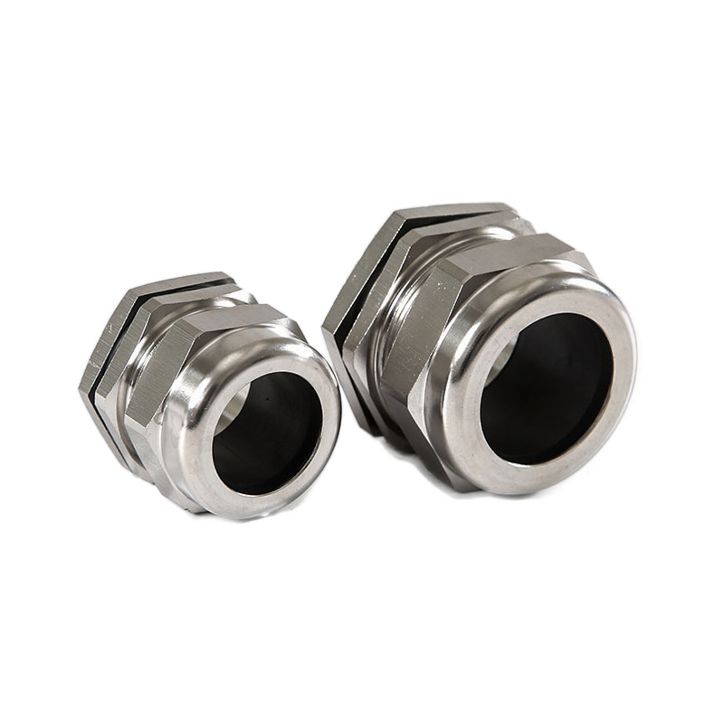
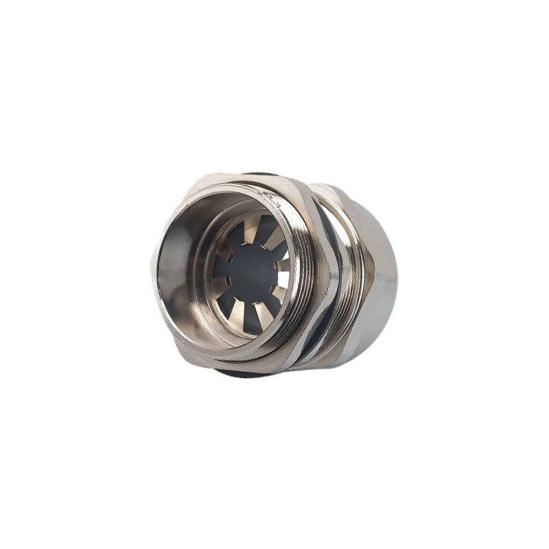
- Marine-grade stainless steel construction
- Specialized coatings for aluminum compatibility
- Galvanic corrosion3 prevention between dissimilar metals
- Salt spray resistance for coastal installations
Service Life Expectations
| Application | Standard Glands | Renewable Energy Glands |
|---|---|---|
| Service Life | 5-10 years | 25+ years |
| UV Resistance | Limited | Enhanced stabilization |
| Temperature Range | -20°C to +60°C | -40°C to +85°C |
| IP Rating | IP65 typical | IP68 standard |
| Warranty | 1-2 years | 10+ years |
Certification Requirements
International Standards:
- IEC 612154 for photovoltaic applications
- IEC 614005 for wind turbine systems
- UL 2703 for solar mounting systems
- TUV certification for European markets
Environmental Testing:
- Salt spray testing (ASTM B117)
- UV exposure testing (ASTM G154)
- Thermal cycling (IEC 60068-2-14)
- Vibration resistance (IEC 60068-2-6)
At Bepto, we’ve developed specialized renewable energy cable glands that exceed standard requirements. Our solar-rated nylon glands include UV stabilizers that maintain performance for 30+ years, while our wind energy stainless steel versions resist salt spray corrosion in the harshest marine environments.
Which Materials Work Best for Solar Applications?
Solar installations require materials that maintain performance under constant UV exposure and temperature cycling.
The best materials for solar applications include UV-stabilized nylon for cost-effective installations, marine-grade stainless steel for premium durability, and specialized polymer compounds with carbon black additives that provide 25+ year UV resistance while maintaining flexibility and sealing performance in desert and tropical climates.
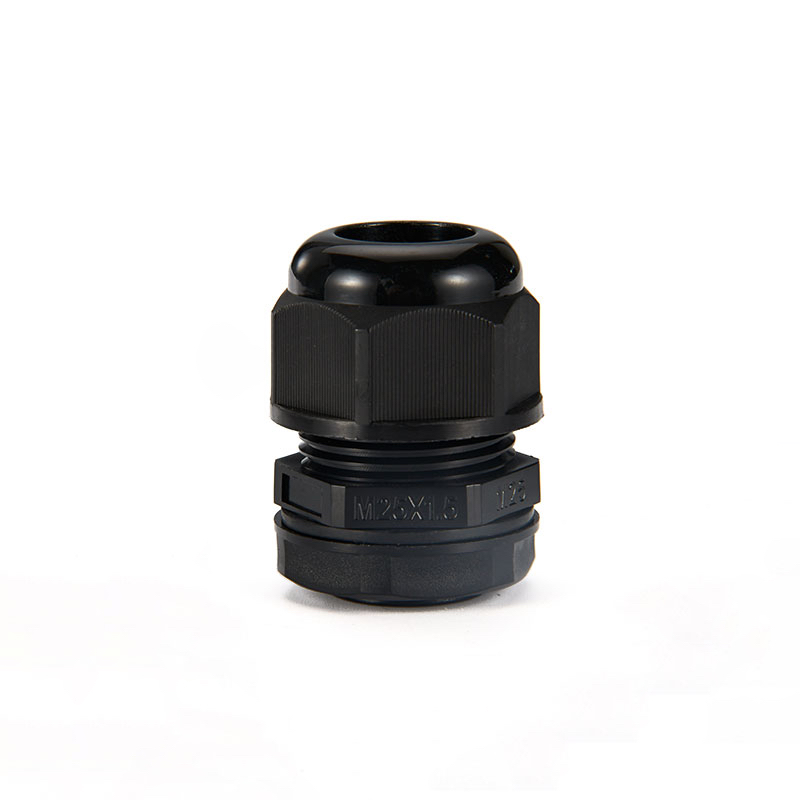
UV-Stabilized Nylon Solutions
Material Advantages:
- Cost-effective for large-scale installations
- Excellent chemical resistance to cleaning agents
- Lightweight reduces structural loading
- Easy installation reduces labor costs
UV Stabilization Technologies:
- Carbon black additives absorb UV radiation
- Hindered amine light stabilizers (HALS)
- UV absorber compounds prevent polymer breakdown
- Color-stable formulations maintain appearance
Stainless Steel Premium Options
Grade Selection Criteria:
- 316L Stainless Steel: Marine environments, coastal installations
- 304 Stainless Steel: Inland installations, moderate environments
- Duplex Stainless: Extreme corrosion resistance applications
Performance Benefits:
- Zero UV degradation concerns
- Excellent thermal conductivity
- Superior mechanical strength
- Recyclable at end of life
Specialized Polymer Compounds
Advanced Material Options:
- Modified PBT: Enhanced UV resistance with glass fiber reinforcement
- PC/ABS Blends: Impact resistance with UV stabilization
- TPE Seals: Flexible sealing elements with weather resistance
Climate-Specific Considerations
Desert Installations:
- High UV intensity requires maximum stabilization
- Sand abrasion resistance needed
- Extreme temperature cycling accommodation
- Minimal moisture but intense heat exposure
Tropical Environments:
- High humidity and temperature combinations
- Fungal and biological growth resistance
- Enhanced moisture sealing requirements
- Chemical resistance to cleaning compounds
Coastal Locations:
- Salt spray corrosion protection
- Enhanced sealing against moisture ingress
- Stainless steel preferred for metal components
- Regular maintenance accessibility considerations
Material Selection Matrix
| Environment | Primary Material | Secondary Option | Seal Material |
|---|---|---|---|
| Desert | UV Nylon | 316L SS | EPDM |
| Tropical | Modified PBT | UV Nylon | FKM |
| Coastal | 316L SS | UV Nylon | FKM |
| Mountain | 304 SS | UV Nylon | EPDM |
Remember Erik from Denmark? His original installation used standard nylon glands that became brittle after two years of North Sea exposure. Our marine-grade stainless steel replacements with FKM seals have maintained perfect sealing performance through multiple storm seasons.
How Do Wind Energy Requirements Differ from Solar?
Wind energy applications face unique challenges including vibration, altitude variations, and extreme mechanical stress.
Wind energy requirements differ through constant vibration exposure, altitude pressure variations, extreme mechanical loading from tower movement, lightning strike considerations, and accessibility challenges that demand ultra-reliable connections with 25+ year maintenance-free operation in locations that may be 100+ meters above ground level.
Vibration and Mechanical Stress
Vibration Sources:
- Rotor blade rotation creates constant vibration
- Tower sway from wind loading
- Gearbox and generator mechanical vibration
- Brake system engagement shock loads
Anti-Vibration Design Features:
- Strain relief systems prevent cable fatigue
- Flexible sealing elements accommodate movement
- Secure mounting prevents loosening
- Cable armor termination distributes stress
Altitude and Pressure Considerations
High Altitude Effects:
- Reduced air pressure affects sealing performance
- UV intensity increases with altitude
- Temperature extremes more severe
- Moisture condensation challenges
Pressure Compensation:
- Breathable membranes prevent vacuum formation
- Pressure-resistant seal designs
- Altitude-rated components to 3000+ meters
- Thermal expansion accommodation
Lightning Protection Integration
Lightning Strike Requirements:
- Conductive path for surge protection
- Bonding to tower grounding system
- Surge-resistant cable connections
- EMI shielding for sensitive electronics
Grounding System Integration:
- Metal cable glands provide conductive path
- Proper bonding to nacelle structure
- Lightning protection system compatibility
- Ground fault protection coordination
Accessibility and Maintenance
Installation Challenges:
- Limited access during installation
- Crane time minimization requirements
- Weather window constraints
- Safety considerations at height
Maintenance Accessibility:
- 25+ year maintenance-free operation required
- Inspection accessibility when possible
- Component replacement difficulty
- Spare parts inventory considerations
Wind-Specific Material Requirements
Enhanced Durability Needs:
- Fatigue resistance for constant flexing
- Impact resistance from debris
- Chemical resistance to lubricants
- Fire resistance for safety systems
Environmental Exposure:
- Extreme wind loading
- Ice formation and shedding
- Salt spray in coastal installations
- UV exposure at high altitudes
Comparison: Solar vs Wind Requirements
| Factor | Solar Applications | Wind Applications |
|---|---|---|
| Vibration | Minimal | Constant high-level |
| Accessibility | Ground level | 100+ meters height |
| Maintenance | Possible | Extremely limited |
| Mechanical Stress | Low | Very high |
| Lightning Risk | Moderate | Extreme |
| Service Life | 25 years | 25+ years |
At Bepto, our wind energy cable glands feature enhanced strain relief systems and vibration-resistant designs. We’ve supplied over 10,000 units to offshore wind farms across Europe, achieving 99.8% reliability in the harshest marine conditions.
What Are the Key Selection Criteria for Long-Term Performance?
Selecting the right cable glands for renewable energy requires balancing performance, cost, and long-term reliability factors.
Key selection criteria for long-term performance include material compatibility with 25+ year service life, environmental rating matching site conditions, certification compliance with renewable energy standards, total cost of ownership including maintenance, and supplier reliability with proven track record in renewable energy applications.
 4") 

Environmental Rating Requirements
IP Rating Selection:
- IP65: Minimum for most renewable applications
- IP68: Required for flood-prone areas
- IP69K: High-pressure cleaning environments
- NEMA 4X: US installations requiring corrosion resistance
Temperature Rating Verification:
- Ambient temperature range at installation site
- Solar heating effects on equipment
- Cold weather performance requirements
- Thermal cycling stress analysis
Certification and Standards Compliance
Essential Certifications:
- UL Listed: Required for US installations
- CE Marking: European market compliance
- TUV Certification: German quality standards
- IECEx: International explosive atmosphere certification
Renewable-Specific Standards:
- IEC 61215: Photovoltaic module qualification
- IEC 61400: Wind turbine safety requirements
- UL 2703: Mounting systems and grounding
- IEEE 1547: Interconnection standards
Total Cost of Ownership Analysis
Initial Cost Factors:
- Material and manufacturing costs
- Certification and testing expenses
- Installation labor requirements
- Shipping and logistics costs
Lifecycle Cost Considerations:
- Maintenance and replacement costs
- System downtime economic impact
- Warranty coverage and terms
- End-of-life disposal costs
Supplier Evaluation Criteria
Technical Capabilities:
- Manufacturing quality systems (ISO9001)
- Testing and certification facilities
- Engineering support capabilities
- Custom design and modification ability
Business Reliability:
- Financial stability and longevity
- Renewable energy market experience
- Global supply chain capabilities
- Technical support and service network
Performance Verification Methods
Pre-Installation Testing:
- Sample testing under actual conditions
- Accelerated aging test programs
- Third-party verification testing
- Pilot installation performance monitoring
Long-Term Monitoring:
- Performance tracking systems
- Failure analysis programs
- Preventive maintenance protocols
- Continuous improvement processes
Selection Decision Matrix
| Criteria | Weight | Evaluation Method |
|---|---|---|
| Environmental Rating | 25% | Site condition analysis |
| Material Durability | 20% | Accelerated testing |
| Certification | 15% | Standards compliance |
| Cost of Ownership | 15% | Lifecycle analysis |
| Supplier Reliability | 15% | Track record review |
| Technical Support | 10% | Service evaluation |
Risk Assessment Framework
Technical Risks:
- Material degradation over time
- Seal failure in extreme conditions
- Mechanical failure from stress
- Electrical performance degradation
Business Risks:
- Supplier discontinuation
- Certification changes
- Market price volatility
- Technology obsolescence
Hassan, a renewable energy developer from Abu Dhabi, initially selected cable glands based solely on lowest price. After experiencing failures in his first solar farm, he adopted our comprehensive selection criteria and achieved 99.9% reliability across 500MW of subsequent installations.
How Do You Ensure Proper Installation in Harsh Environments?
Proper installation techniques are critical for achieving design life in renewable energy applications.
Ensuring proper installation in harsh environments requires specialized tools and techniques, environmental protection during installation, quality control procedures, proper training for installation teams, and comprehensive testing protocols that verify performance before system commissioning and throughout the operational lifecycle.
Pre-Installation Preparation
Site Assessment Requirements:
- Environmental condition documentation
- Access route planning and safety analysis
- Weather window identification
- Equipment and tool requirements verification
Material Handling Protocols:
- UV protection during storage
- Temperature control for sensitive materials
- Moisture protection before installation
- Inventory management and tracking
Installation Tool Requirements
Specialized Equipment:
- Calibrated torque wrenches for proper tightening
- Cable stripping tools for armor termination
- Continuity testers for grounding verification
- Environmental protection equipment
Safety Equipment:
- Fall protection systems for height work
- Electrical safety equipment and procedures
- Weather protection for installation teams
- Emergency communication systems
Environmental Protection During Installation
Weather Considerations:
- Temperature limits for material handling
- Wind speed restrictions for safe work
- Moisture protection during installation
- UV protection for extended work periods
Contamination Prevention:
- Clean installation environment maintenance
- Dust and debris exclusion methods
- Chemical contamination avoidance
- Proper material storage and handling
Quality Control Procedures
Installation Verification Steps:
- Visual inspection of all components
- Torque verification with calibrated tools
- Continuity testing of grounding connections
- Seal integrity verification
- Final system integration testing
Documentation Requirements:
- Installation checklists and sign-offs
- Torque values and test results
- Material traceability records
- As-built drawings and specifications
Training and Certification
Installer Qualification:
- Renewable energy installation experience
- Cable gland specific training programs
- Safety certification requirements
- Ongoing education and updates
Quality Assurance Programs:
- Installation procedure standardization
- Regular audits and inspections
- Continuous improvement processes
- Best practice sharing and implementation
Testing and Commissioning
Pre-Energization Testing:
- Insulation resistance measurement
- Ground fault circuit verification
- Continuity testing of all connections
- Environmental seal integrity testing
Performance Monitoring:
- Initial baseline establishment
- Periodic inspection schedules
- Performance trending analysis
- Preventive maintenance planning
Common Installation Mistakes
Material Handling Errors:
- UV exposure during installation
- Contamination of sealing surfaces
- Improper storage conditions
- Mixing of incompatible materials
Installation Technique Problems:
- Inadequate torque application
- Poor surface preparation
- Incorrect cable armor termination
- Insufficient strain relief
Environmental-Specific Considerations
Desert Installations:
- Sand contamination prevention
- Extreme temperature work scheduling
- UV protection for materials and workers
- Water scarcity planning
Offshore Wind:
- Weather window coordination
- Salt spray protection during installation
- Crane vessel scheduling optimization
- Emergency evacuation procedures
At Bepto, we provide comprehensive installation training and support for renewable energy projects. Our field service team has successfully commissioned over 2GW of solar and wind installations worldwide, achieving industry-leading reliability through proper installation techniques.
Conclusion
Cable glands for renewable energy applications require specialized design, materials, and installation techniques to achieve 25+ year service life in harsh outdoor environments. Success depends on understanding the unique requirements of solar and wind applications, selecting appropriate materials and certifications, and implementing proper installation and testing procedures.
The key differentiators are enhanced UV resistance, expanded temperature ranges, superior sealing performance, and long-term material stability. Whether you’re developing utility-scale solar farms or offshore wind installations, the right cable gland selection and installation practices ensure reliable power generation and minimize lifecycle costs.
At Bepto, we’ve dedicated significant resources to developing renewable energy-specific solutions that meet the demanding requirements of clean energy infrastructure. Our comprehensive product line, technical support, and field service capabilities help customers achieve optimal performance in their renewable energy investments 😉
FAQs About Renewable Energy Cable Glands
Q: What’s the difference between regular cable glands and renewable energy cable glands?
A: Renewable energy cable glands feature enhanced UV stabilization, wider temperature ranges (-40°C to +85°C), superior sealing (IP68), and 25+ year service life ratings compared to standard industrial glands with 5-10 year lifespans and limited environmental resistance.
Q: How do I choose between nylon and stainless steel for solar applications?
A: Choose UV-stabilized nylon for cost-effective installations in moderate environments, and stainless steel for coastal, desert, or extreme conditions where maximum durability is required. Consider total cost of ownership including maintenance and replacement costs over 25+ years.
Q: What IP rating do I need for wind turbine applications?
A: Wind turbines typically require IP68 rating for nacelle installations due to extreme weather exposure and limited maintenance access. Offshore installations may need even higher protection levels with additional corrosion resistance features.
Q: How often should renewable energy cable glands be inspected?
A: Solar installations should be inspected annually during routine maintenance, while wind turbines require inspection every 6 months or per manufacturer recommendations. Any signs of UV degradation, seal deterioration, or mechanical damage require immediate attention.
Q: Can I use standard installation techniques for renewable energy cable glands?
A: No, renewable energy applications require specialized installation techniques including proper torque specifications, environmental protection during installation, enhanced testing procedures, and documentation requirements to ensure 25+ year performance in harsh outdoor conditions.
-
See the official definitions from the IEC standard for IP68 (submersion) and IP69K (high-pressure wash-down) ratings. ↩
-
Learn about the mechanisms used to protect polymers from degradation caused by ultraviolet radiation. ↩
-
Understand the electrochemical process of galvanic corrosion and how it affects dissimilar metals, especially in harsh environments. ↩
-
Access the official IEC overview for the standard covering terrestrial photovoltaic (PV) module design qualification and type approval. ↩
-
View the official IEC overview for the standard series related to wind energy generation systems. ↩
