

Solar installers face catastrophic system failures and safety hazards when they select incompatible cables for MC4 connectors, leading to overheating, voltage drop, arc faults, and fire risks that can destroy entire photovoltaic installations worth hundreds of thousands of dollars. The wrong cable choice creates high resistance connections, inadequate current capacity, and insulation breakdown that triggers inverter shutdowns, reduces energy production, and violates electrical codes, potentially resulting in failed inspections, insurance claim denials, and dangerous electrical conditions that threaten both equipment and personnel safety.
Selecting the right cable for MC4 connectors requires matching cable gauge to system current capacity, choosing appropriate insulation ratings for environmental conditions, ensuring proper voltage ratings for system design, and verifying compatibility with connector specifications for reliable long-term performance. The cable must handle maximum system current with minimal voltage drop, withstand UV exposure and temperature extremes, maintain insulation integrity over 25+ year system life, and provide proper mechanical support for outdoor installations while meeting all applicable electrical codes and safety standards.
Last month, I received an urgent call from Marcus Thompson, project manager at a leading solar EPC company in Phoenix, Arizona, who discovered that using undersized 12 AWG cable with MC4 connectors on a 400-amp commercial installation had created 23 overheating connections showing temperatures exceeding 90°C during thermal imaging inspection. The local electrical inspector immediately shut down the 1.5MW system, forcing a complete cable replacement project costing $85,000 and delaying commissioning by eight weeks. This expensive lesson demonstrates why proper cable selection for MC4 connectors is absolutely critical for every solar professional! ⚡
Table of Contents
- What Cable Specifications Are Critical for MC4 Connectors?
- How Do You Calculate the Right Cable Gauge for Your System?
- Which Insulation Types Work Best with MC4 Connectors?
- What Are the Key Installation Considerations for MC4 Cable Systems?
- How Do You Ensure Long-Term Reliability and Code Compliance?
- FAQs About MC4 Connector Cable Selection
What Cable Specifications Are Critical for MC4 Connectors?
Understanding the essential cable specifications ensures proper MC4 connector performance and system safety.
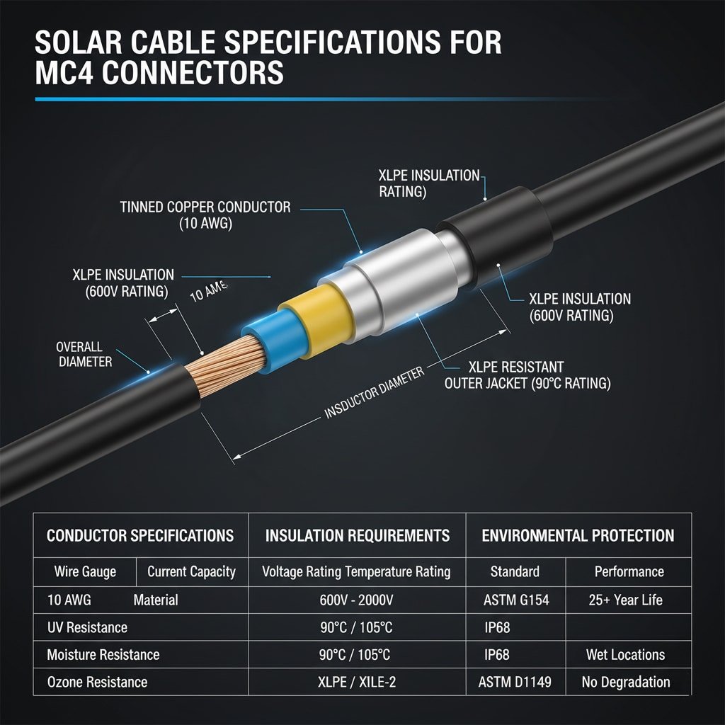
Critical cable specifications for MC4 connectors include conductor size (10-14 AWG1 typically), insulation voltage rating (600V minimum for most applications), temperature rating (90°C minimum for outdoor use), UV resistance for sunlight exposure, and proper conductor material (tinned copper2 preferred). The cable must also meet specific dimensional requirements for MC4 connector compatibility, including conductor diameter, insulation thickness, and overall cable diameter to ensure proper crimping, sealing, and mechanical retention within the connector assembly.
Conductor Specifications
Wire Gauge Requirements: MC4 connectors typically accommodate 10, 12, and 14 AWG conductors, with specific connector models designed for each gauge range.
Conductor Material: Tinned copper conductors provide superior corrosion resistance and connection reliability compared to bare copper in outdoor environments.
Stranding Configuration: Fine-strand conductors offer better flexibility and vibration resistance than solid or coarse-strand alternatives.
Current Capacity: Conductor ampacity must exceed maximum system current with appropriate derating factors for temperature and installation conditions.
Insulation Requirements
Voltage Rating: Minimum 600V insulation rating for most photovoltaic applications, with 1000V or 2000V ratings for higher voltage systems.
Temperature Rating: 90°C minimum temperature rating for outdoor installations, with 105°C preferred for extreme climate conditions.
Material Properties: Cross-linked polyethylene (XLPE)3 or electron beam cross-linked (XLPE-2) insulation provides optimal performance and longevity.
Thickness Standards: Proper insulation thickness ensures electrical safety and mechanical protection during installation and operation.
Environmental Protection
| Protection Type | Specification | Application | Performance Standard |
|---|---|---|---|
| UV Resistance | ASTM G154 tested | Direct sunlight | 25+ year life |
| Moisture Resistance | Water immersion rated | Wet locations | IP67/IP68 compatible |
| Temperature Range | -40°C to +90°C | Extreme climates | UL 4703 certified |
| Ozone Resistance | ASTM D1149 tested | High altitude/pollution | No cracking/degradation |
Mechanical Properties
Flexibility: Cable must maintain flexibility at low temperatures while resisting damage from thermal cycling and mechanical stress.
Crush Resistance: Adequate mechanical strength to withstand installation stresses and long-term environmental loading.
Bend Radius: Minimum bend radius specifications ensure cable integrity during installation and prevent conductor damage.
Abrasion Resistance: Protective jacket materials resist wear from wind-induced movement and installation handling.
Certification and Standards
UL 4703 Listing: Primary certification for photovoltaic wire and cable used in solar installations throughout North America.
TUV Certification: European certification standard for solar cables used in international markets and high-quality installations.
RoHS Compliance4: Environmental compliance ensuring cables are free from hazardous substances and suitable for global markets.
NEC Compliance: Meeting National Electrical Code requirements for photovoltaic system wiring and installation methods.
Working with Ahmed Hassan, electrical contractor for a major solar farm project in Dubai, UAE, I learned that Middle Eastern installations face extreme temperature and UV conditions that demand the highest quality cable specifications. Ahmed told me that cable failures account for 40% of early system problems in desert installations, with inadequate UV protection and temperature ratings being the primary failure modes. This experience reinforced the critical importance of proper cable specification for MC4 connector applications! 🌞
How Do You Calculate the Right Cable Gauge for Your System?
Proper cable gauge calculation ensures adequate current capacity and minimal voltage drop for optimal system performance.
Cable gauge calculation for MC4 connectors requires determining maximum system current, applying appropriate derating factors for temperature and installation conditions, calculating voltage drop for the specific cable run length, and selecting the largest gauge needed to meet both ampacity and voltage drop requirements. Professional installations typically limit voltage drop to 2-3% maximum, which often requires larger cable gauges than basic ampacity calculations alone would suggest, especially for longer cable runs or high-current applications.
Current Capacity Calculations
System Current Determination: Calculate maximum current based on module specifications, string configuration, and system design parameters.
Safety Factors: Apply 125% safety factor as required by NEC for continuous current applications in photovoltaic systems.
Derating Factors: Account for ambient temperature, conduit fill, and bundling effects that reduce cable current-carrying capacity.
Future Expansion: Consider potential system expansion when selecting cable gauge to avoid costly upgrades later.
Voltage Drop Analysis
Acceptable Limits: Industry best practice limits voltage drop to 2% for DC circuits and 3% maximum for combined DC and AC circuits.
Calculation Methods: Use precise voltage drop formulas accounting for cable resistance, length, and actual operating current.
Temperature Effects: Higher operating temperatures increase cable resistance and voltage drop beyond standard calculations.
String Performance: Excessive voltage drop reduces string voltage and can cause inverter shutdown or reduced power output.
Cable Gauge Selection Matrix
| System Current | Cable Run Length | Minimum AWG | Voltage Drop | Application |
|---|---|---|---|---|
| 10-15A | 0-50 feet | 12 AWG | <2% | Residential strings |
| 15-25A | 0-50 feet | 10 AWG | <2% | Commercial strings |
| 10-15A | 50-100 feet | 10 AWG | <3% | Long residential runs |
| 25-40A | 0-50 feet | 8 AWG | <2% | High-current applications |
Environmental Derating
Temperature Correction: Apply temperature correction factors based on local climate conditions and installation environment.
Altitude Adjustments: High-altitude installations may require additional derating for reduced air density and cooling.
Installation Method: Cable installation method (conduit, cable tray, direct burial) affects current-carrying capacity.
Bundling Effects: Multiple cables in close proximity require derating factors to prevent overheating.
Calculation Tools and Resources
Software Solutions: Professional cable sizing software provides accurate calculations for complex installations with multiple variables.
Manufacturer Tables: Cable manufacturers provide comprehensive ampacity and voltage drop tables for their specific products.
Code References: NEC Article 690 provides detailed requirements and calculation methods for photovoltaic system wiring.
Engineering Support: Consulting with electrical engineers ensures proper cable sizing for complex or critical installations.
Which Insulation Types Work Best with MC4 Connectors?
Selecting appropriate insulation materials ensures long-term reliability and compatibility with MC4 connector systems.
The best insulation types for MC4 connectors include cross-linked polyethylene (XLPE) for superior temperature and UV resistance, thermoplastic elastomer (TPE) for flexibility and environmental protection, and electron beam cross-linked materials for enhanced durability and performance. These insulation materials provide excellent compatibility with MC4 connector sealing systems, maintain electrical properties over 25+ year service life, resist environmental degradation from UV exposure and temperature cycling, and offer proper mechanical properties for outdoor photovoltaic installations.

Cross-Linked Polyethylene (XLPE)
Performance Advantages: XLPE insulation offers exceptional temperature resistance, chemical stability, and long-term aging characteristics.
UV Resistance: Specially formulated XLPE compounds provide excellent resistance to UV degradation and maintain properties over decades.
Temperature Range: Operating temperature range from -40°C to +90°C covers most installation environments and climate conditions.
Electrical Properties: Superior dielectric strength and insulation resistance maintain electrical safety throughout system lifetime.
Thermoplastic Elastomer (TPE)
Flexibility Benefits: TPE insulation maintains flexibility at low temperatures while providing excellent high-temperature performance.
Environmental Resistance: Outstanding resistance to ozone, weathering, and chemical exposure common in outdoor installations.
Processing Advantages: TPE materials allow precise control of cable dimensions and properties during manufacturing processes.
Recyclability: Thermoplastic nature allows recycling and reprocessing, supporting environmental sustainability goals.
Insulation Performance Comparison
| Insulation Type | Temperature Rating | UV Resistance | Flexibility | Cost Factor |
|---|---|---|---|---|
| XLPE | 90-105°C | Excellent | Good | Standard |
| TPE | 90-125°C | Excellent | Superior | Premium |
| PVC | 60-75°C | Poor | Fair | Economy |
| EPR | 90°C | Good | Excellent | Premium |
Jacket Materials
Polyurethane Jackets: Provide superior abrasion resistance and mechanical protection for harsh installation environments.
Halogen-Free Compounds: Low-smoke, zero-halogen materials meet environmental and safety requirements for sensitive installations.
Color Coding: Proper color coding (red for positive, black for negative) ensures correct polarity connections and code compliance.
Marking Requirements: Clear, permanent marking with cable specifications, certifications, and manufacturer identification.
Compatibility Considerations
Connector Sealing: Insulation materials must be compatible with MC4 connector sealing systems to maintain IP67/IP68 ratings.
Thermal Expansion: Matching thermal expansion coefficients between cable and connector materials prevents seal degradation.
Chemical Compatibility: Insulation materials must resist degradation from cleaning solvents and maintenance chemicals.
Mechanical Interface: Proper hardness and surface properties ensure reliable crimping and mechanical retention.
At Bepto, we’ve extensively tested various cable insulation types with our solar connector products to ensure optimal compatibility and performance. Our engineering team has validated XLPE and TPE insulation materials through accelerated aging tests, thermal cycling, and UV exposure testing to guarantee 25+ year service life. When you choose Bepto solar connectors, you get comprehensive compatibility data and technical support to ensure your cable selection delivers maximum reliability and performance! 🔧
What Are the Key Installation Considerations for MC4 Cable Systems?
Proper installation techniques ensure reliable MC4 connector performance and long-term system integrity.
Key installation considerations for MC4 cable systems include proper crimping techniques using manufacturer-specified tools, adequate strain relief to prevent mechanical stress on connections, appropriate cable routing to minimize UV exposure and physical damage, and proper grounding and bonding for electrical safety. Professional installations also require attention to cable support spacing, bend radius limitations, thermal expansion accommodation, and protection from sharp edges or abrasive surfaces that could damage cable insulation over time.
Crimping and Assembly Techniques
Tool Selection: Use only manufacturer-specified crimping tools calibrated for the specific MC4 connector and cable combination being installed.
Crimp Quality: Proper crimping creates gas-tight connections5 with optimal contact resistance and mechanical retention strength.
Inspection Procedures: Visual and mechanical inspection of each crimp connection ensures quality and reliability before system energization.
Pull Testing: Sample pull testing verifies proper crimp integrity and mechanical retention according to manufacturer specifications.
Cable Routing and Support
Support Spacing: Maintain proper cable support spacing (typically 3-5 feet) to prevent sagging and mechanical stress on connections.
Bend Radius: Respect minimum bend radius requirements to prevent conductor damage and insulation stress during installation.
Thermal Expansion: Allow for thermal expansion and contraction through proper cable routing and expansion loops.
Protection Methods: Use cable trays, conduits, or protective covers where cables are exposed to mechanical damage or extreme weather.
Installation Best Practices
| Installation Aspect | Requirement | Best Practice | Common Mistake |
|---|---|---|---|
| Crimp tool calibration | Annual calibration | Monthly verification | Using uncalibrated tools |
| Cable support | Every 4 feet maximum | Every 3 feet | Inadequate support |
| Bend radius | 8x cable diameter | 10x cable diameter | Sharp bends |
| Strain relief | At all terminations | Proper strain relief boots | No strain relief |
Environmental Protection
UV Exposure: Minimize direct sunlight exposure through proper routing and protective covers where necessary.
Moisture Protection: Ensure proper sealing at all connection points and use appropriate cable entry methods.
Temperature Management: Route cables to avoid hot surfaces and provide adequate ventilation for heat dissipation.
Chemical Protection: Protect cables from exposure to cleaning chemicals, bird droppings, and other potentially corrosive substances.
Grounding and Bonding
Equipment Grounding: Proper grounding of all metallic components ensures electrical safety and code compliance.
Bonding Continuity: Maintain grounding conductor continuity throughout the cable system for effective fault protection.
Grounding Electrode: Connect system grounding to appropriate grounding electrodes as required by local electrical codes.
Lightning Protection: Consider lightning protection systems for installations in high-lightning-activity areas.
Quality Control Procedures
Pre-Installation Inspection: Inspect all cables and connectors for damage before installation begins.
Installation Testing: Perform continuity, insulation resistance, and thermal imaging testing after installation completion.
Documentation: Maintain detailed records of cable specifications, installation methods, and test results for warranty and maintenance purposes.
Final Inspection: Conduct comprehensive final inspection before system commissioning and utility interconnection.
How Do You Ensure Long-Term Reliability and Code Compliance?
Implementing comprehensive quality assurance and maintenance programs ensures MC4 cable systems meet performance and safety requirements.
Ensuring long-term reliability and code compliance requires selecting UL-listed cables meeting NEC requirements, implementing regular inspection and maintenance schedules, monitoring system performance for early failure detection, and maintaining detailed documentation for warranty and regulatory compliance. Professional installations should include thermal imaging inspections, contact resistance testing, insulation resistance verification, and systematic replacement of components showing signs of degradation before they cause system failures or safety hazards.
Code Compliance Requirements
NEC Article 690: Comprehensive requirements for photovoltaic system wiring, including cable specifications and installation methods.
UL Standards: UL 4703 certification for photovoltaic wire and cable ensures safety and performance standards compliance.
Local Amendments: Local electrical codes may have additional requirements beyond national standards that must be followed.
Inspection Requirements: Regular electrical inspections ensure ongoing compliance with applicable codes and safety standards.
Preventive Maintenance Programs
Visual Inspections: Regular visual inspections identify signs of cable damage, connector degradation, or environmental exposure issues.
Thermal Imaging: Annual thermal imaging inspections detect high-resistance connections before they cause failures or safety hazards.
Performance Monitoring: Continuous system monitoring identifies performance degradation that may indicate cable or connection problems.
Cleaning Procedures: Regular cleaning removes contamination that could affect connector performance or cause tracking failures.
Testing and Verification
| Test Type | Frequency | Acceptance Criteria | Equipment Required |
|---|---|---|---|
| Visual inspection | Quarterly | No visible damage | Visual examination |
| Thermal imaging | Annually | <10°C above ambient | IR camera |
| Insulation resistance | Annually | >1000 MΩ | Megohmmeter |
| Contact resistance | As needed | <0.5 mΩ | Micro-ohmmeter |
Documentation and Record Keeping
Installation Records: Detailed documentation of cable specifications, installation methods, and initial test results.
Maintenance Logs: Comprehensive records of all maintenance activities, inspections, and component replacements.
Performance Data: Long-term performance monitoring data to identify trends and predict maintenance needs.
Compliance Certificates: Certificates demonstrating ongoing compliance with applicable codes and standards.
Component Replacement Strategies
Predictive Replacement: Replace components showing signs of degradation before they cause system failures or safety issues.
Scheduled Replacement: Systematic replacement of critical components based on manufacturer recommendations and service life data.
Emergency Procedures: Established procedures for rapid response to component failures that affect system safety or performance.
Inventory Management: Maintain adequate spare parts inventory to support maintenance and emergency repair activities.
Performance Optimization
System Monitoring: Advanced monitoring systems provide real-time performance data and early warning of potential problems.
Data Analysis: Regular analysis of performance data identifies optimization opportunities and maintenance needs.
Upgrade Planning: Systematic evaluation of upgrade opportunities to improve system performance and reliability.
Technology Updates: Stay current with evolving technology and code requirements that may affect system performance.
Working with Jennifer Martinez, O&M manager for a 500MW solar portfolio in California, I’ve seen how proactive maintenance and quality cable selection dramatically improve system reliability. Jennifer’s team has achieved 99.7% uptime across their portfolio by implementing rigorous cable inspection programs and using only premium-grade cables with proper MC4 connector compatibility. Their systematic approach to cable system maintenance has prevented over 200 potential failures and saved millions in lost revenue over the past five years! 📊
Conclusion
Selecting the right cable for MC4 connectors is a critical decision that affects system safety, performance, and long-term reliability over the 25+ year operational life of photovoltaic installations. Proper cable selection requires careful consideration of conductor size, insulation type, environmental ratings, and compatibility with MC4 connector specifications, while installation quality and ongoing maintenance programs ensure optimal performance and code compliance. The investment in premium cables and professional installation practices pays dividends through reduced maintenance costs, improved system reliability, and enhanced safety that protects both equipment and personnel. By following the comprehensive guidelines outlined in this guide, solar professionals can ensure their MC4 cable systems deliver maximum performance, safety, and return on investment throughout their operational lifetime.
FAQs About MC4 Connector Cable Selection
Q: What cable gauge should I use with MC4 connectors for residential solar?
A: Most residential solar installations use 10 or 12 AWG cable with MC4 connectors, depending on string current and cable run length. Calculate based on maximum string current plus 125% safety factor, with voltage drop limited to 2-3% maximum.
Q: Can I use regular electrical wire with MC4 connectors?
A: No, you must use UL 4703 listed photovoltaic wire specifically designed for solar applications. Regular electrical wire lacks the UV resistance, temperature rating, and environmental protection required for outdoor solar installations.
Q: How do I know if my cable is compatible with MC4 connectors?
A: Check that cable conductor size matches MC4 connector specifications (typically 10-14 AWG), verify proper insulation diameter for connector sealing, and ensure cable meets UL 4703 certification requirements for photovoltaic applications.
Q: What’s the difference between XLPE and TPE insulation for solar cables?
A: XLPE offers excellent temperature and UV resistance at standard cost, while TPE provides superior flexibility and environmental protection at premium pricing. Both work well with MC4 connectors when properly specified.
Q: How often should I inspect MC4 cable connections?
A: Perform visual inspections quarterly and thermal imaging inspections annually to detect potential problems early. Additional inspections may be needed after severe weather events or if performance monitoring indicates issues.
-
See a chart and explanation of the American Wire Gauge (AWG) standard, where a smaller gauge number corresponds to a larger wire diameter. ↩
-
Learn why copper wire is often tinned, a process that adds a thin layer of tin to protect against corrosion and improve solderability. ↩
-
Explore the properties of Cross-linked Polyethylene (XLPE), a thermoset insulation material known for its excellent thermal, electrical, and weather-resistant characteristics. ↩
-
Understand the Restriction of Hazardous Substances (RoHS) directive, which originated in the European Union and restricts the use of specific hazardous materials found in electrical and electronic products. ↩
-
Discover the importance of a gas-tight connection, a type of crimp that is so tight it prevents oxygen and moisture from oxidizing the metals, ensuring a long-term reliable connection. ↩
