Short circuit faults cause devastating electrical fires, equipment damage, and safety hazards when inadequate cable protection allows fault currents to create dangerous arcing, overheating, and insulation breakdown, while improper cable gland installation compromises circuit integrity and creates additional fault paths that can bypass protective devices and escalate minor faults into catastrophic failures.
Cable glands contribute to short circuit protection under BS 76711 by maintaining cable integrity, providing proper earthing continuity, preventing ingress that could cause faults, ensuring secure cable termination, and supporting the overall protective conductor system that enables circuit breakers and RCDs2 to operate effectively during fault conditions while maintaining IP ratings and mechanical protection. Proper cable gland selection and installation is essential for comprehensive electrical safety.
Having worked with electrical contractors across major UK infrastructure projects, from London’s Crossrail installations to offshore wind farms in the North Sea, I’ve witnessed how proper cable gland installation can be the difference between a minor fault being safely cleared and a catastrophic electrical fire. Understanding BS 7671 requirements for cable protection is crucial for every electrical professional.
Table of Contents
- What Are the BS 7671 Requirements for Short Circuit Protection?
- How Do Cable Glands Support Circuit Protection Systems?
- What Role Do Cable Glands Play in Earthing and Bonding?
- How Do You Select Cable Glands for Short Circuit Protection Compliance?
- What Are the Installation Requirements for BS 7671 Compliance?
- FAQs About Cable Glands and Short Circuit Protection
What Are the BS 7671 Requirements for Short Circuit Protection?
BS 7671 requires comprehensive short circuit protection through proper protective device selection, adequate fault current ratings, correct earthing arrangements, secure cable terminations, and environmental protection that prevents fault conditions, with cable glands playing a critical role in maintaining circuit integrity, providing earthing continuity, and preventing ingress that could compromise protection systems or create additional fault paths.
Understanding these requirements ensures electrical installations meet safety standards and provide reliable protection.

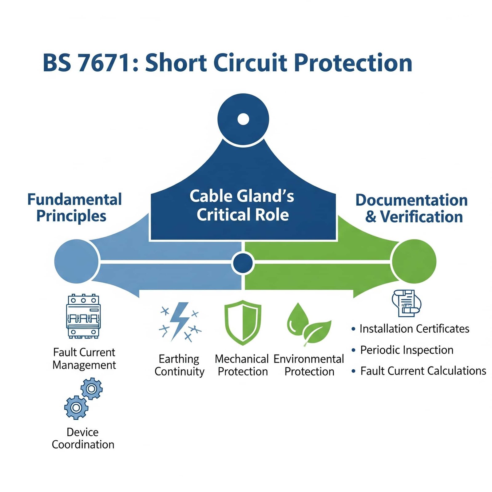
Fundamental Protection Principles
Fault Current Management: BS 7671 requires that all circuits can safely carry and clear fault currents without causing fire or injury hazards.
Protective Device Coordination: Circuit breakers, fuses, and RCDs must be properly coordinated to clear faults quickly and selectively.
Earth Fault Protection: Reliable earthing systems must ensure fault currents have a safe path to earth, enabling protective devices to operate.
Cable Integrity: Cables must be protected from mechanical damage, environmental conditions, and thermal effects that could cause faults.
Cable Protection Requirements
Mechanical Protection: Cables must be protected from physical damage that could cause short circuits or earth faults.
Environmental Protection: Ingress protection prevents moisture, dust, and contaminants from causing insulation breakdown and faults.
Thermal Management: Cable installations must prevent overheating that could lead to insulation failure and short circuits.
Segregation Requirements: Different circuit types must be properly segregated to prevent interference and fault propagation.
Earthing and Bonding Standards
Protective Conductor Continuity: All metallic parts must be properly bonded to ensure fault currents have a reliable path to earth.
Earth Electrode Systems: Adequate earth electrode arrangements must provide low-resistance paths for fault currents.
Equipotential Bonding: Main and supplementary bonding must eliminate dangerous potential differences during fault conditions.
Cable Gland Earthing: Metal cable glands must be properly earthed to maintain protective conductor continuity.
Documentation and Verification
| Requirement | Purpose | Cable Gland Impact |
|---|---|---|
| Installation Certificates | Verify compliance | Proper gland selection and installation |
| Periodic Inspection | Maintain safety standards | Gland condition and earthing integrity |
| Fault Current Calculations | Ensure adequate protection | Gland current-carrying capacity |
| Earth Fault Loop Impedance3 | Verify protection operation | Earthing continuity through glands |
James, an electrical contractor working on a major hospital expansion in Manchester, faced repeated RCD tripping issues that were traced to inadequate cable gland sealing allowing moisture ingress. The damp conditions were creating earth leakage currents that interfered with the protection systems. We provided IP68-rated4 cable glands with enhanced sealing that eliminated the moisture ingress problem, ensuring reliable operation of the critical medical equipment protection systems. 😊
How Do Cable Glands Support Circuit Protection Systems?
Cable glands support circuit protection systems by maintaining cable mechanical integrity, providing secure terminations that prevent loose connections, ensuring proper earthing continuity for fault current paths, preventing environmental ingress that could cause faults, and maintaining IP ratings that protect sensitive protection equipment while supporting the overall electrical safety system required by BS 7671 standards.
Proper cable gland selection and installation is essential for reliable protection system operation.
Mechanical Integrity and Fault Prevention
Strain Relief Function: Cable glands provide essential strain relief that prevents cable damage from mechanical stress, vibration, and thermal movement.
Secure Termination: Proper cable termination prevents loose connections that can cause arcing, overheating, and potential fire hazards.
Cable Support: Adequate cable support prevents damage from excessive bending, crushing, or pulling forces that could compromise insulation.
Ingress Protection: Environmental sealing prevents moisture, dust, and contaminants from entering enclosures and causing faults.
Earthing System Integration
Protective Conductor Continuity: Metal cable glands provide continuous earthing paths for cable armor, screens, and protective conductors.
Bonding Requirements: Proper bonding of cable glands ensures all metallic parts are at the same potential during fault conditions.
Earth Fault Current Paths: Cable glands must provide low-impedance paths for earth fault currents to enable protective device operation.
EMC Considerations: Screened cable glands maintain electromagnetic compatibility by providing 360-degree shielding continuity.
Protection System Compatibility
Current Rating Compliance: Cable glands must have adequate current-carrying capacity for the circuits they serve, including fault current conditions.
Voltage Rating Requirements: Insulation levels must be appropriate for the system voltage and fault conditions that may occur.
Arc Fault Considerations: Proper installation prevents arc fault conditions that could bypass or interfere with protection systems.
Selective Coordination: Cable gland installations must not interfere with selective coordination of protective devices.
Environmental Protection Standards
IP Rating Maintenance: Cable glands must maintain specified IP ratings to protect sensitive protection equipment from environmental conditions.
Temperature Performance: Thermal stability ensures reliable operation across the full range of operating and fault conditions.
Chemical Resistance: Resistance to environmental chemicals prevents degradation that could compromise protection system integrity.
UV Stability: Outdoor installations require UV-resistant materials to maintain long-term performance and protection.
Integration with Modern Protection Systems
Digital Protection Compatibility: Modern protection systems require reliable earthing and screening that cable glands must support.
Communication System Protection: Data and communication cables require specialized cable glands that maintain signal integrity while providing protection.
Renewable Energy Integration: Solar and wind installations require cable glands that support DC fault protection and arc fault detection systems.
Smart Grid Applications: Advanced metering and control systems require cable glands that support both power and communication circuit protection.
What Role Do Cable Glands Play in Earthing and Bonding?
Cable glands play a critical role in earthing and bonding by providing continuous electrical paths for protective conductors, maintaining low-impedance connections for fault currents, ensuring proper bonding of cable armor and screens, supporting equipotential bonding requirements, and integrating with main earthing terminals while meeting BS 7671 requirements for protective conductor continuity and earth fault loop impedance.
Proper earthing through cable glands is essential for electrical safety and protection system effectiveness.
Protective Conductor Continuity
Armor Earthing: Cable glands provide the primary connection point for earthing steel wire armor (SWA) and other metallic cable components.
Screen Termination: Screened cables require proper termination of their metallic screens through cable glands to maintain earthing continuity.
Conductor Routing: Cable glands must accommodate protective conductors without compromising their integrity or current-carrying capacity.
Connection Integrity: Reliable electrical connections ensure fault currents have uninterrupted paths to the main earthing terminal.
Earth Fault Loop Impedance
Low-Impedance Paths: Cable glands must provide low-impedance connections to ensure earth fault loop impedance values meet BS 7671 requirements.
Connection Quality: High-quality connections prevent voltage drops that could affect protective device operation during fault conditions.
Corrosion Resistance: Materials and finishes must resist corrosion that could increase impedance over time and compromise protection.
Testing Access: Installation methods must allow for earth fault loop impedance testing as required by BS 7671.
Equipotential Bonding Integration
Main Bonding Connections: Cable glands may form part of the main equipotential bonding system for metallic services and structural elements.
Supplementary Bonding: In special locations, cable glands contribute to supplementary equipotential bonding requirements.
Metallic Service Integration: Cable glands connecting to metallic conduit systems must maintain bonding continuity throughout the installation.
Potential Equalization: Proper bonding prevents dangerous potential differences during fault conditions.
Special Location Requirements
| Location Type | Earthing Requirements | Cable Gland Considerations |
|---|---|---|
| Bathrooms | Enhanced bonding | IP-rated glands, supplementary bonding |
| Swimming Pools | Zone-specific requirements | Specialized materials, enhanced sealing |
| Medical Locations | Medical earthing systems | High-reliability connections, testing access |
| Explosive Atmospheres | ATEX compliance5 | Explosion-proof glands, certified earthing |
| Outdoor Installations | Lightning protection | Surge-resistant materials, enhanced bonding |
Testing and Verification Requirements
Continuity Testing: All protective conductor connections through cable glands must be tested for continuity and low resistance.
Earth Fault Loop Impedance Testing: Complete earth fault loops including cable gland connections must meet specified impedance values.
Insulation Resistance Testing: Cable gland installations must not compromise insulation resistance between conductors and earth.
Periodic Inspection: Regular inspection of cable gland earthing connections ensures continued compliance with BS 7671.
Hassan, who manages electrical installations at a petrochemical facility in Aberdeen, Scotland, required cable glands that could maintain reliable earthing in the corrosive North Sea environment. Standard brass glands were experiencing corrosion that increased earth fault loop impedance beyond BS 7671 limits. We provided marine-grade stainless steel cable glands with enhanced corrosion resistance that maintained consistent earthing performance for over 5 years, ensuring continued compliance with safety standards and reliable protection system operation.
How Do You Select Cable Glands for Short Circuit Protection Compliance?
Selecting cable glands for short circuit protection compliance requires evaluating fault current ratings, ensuring adequate earthing capability, verifying IP rating requirements, confirming material compatibility with protection systems, assessing installation environment conditions, and ensuring compliance with BS 7671 standards for mechanical protection, environmental sealing, and electrical performance while supporting overall circuit protection objectives.
Proper selection ensures cable glands enhance rather than compromise electrical safety systems.
Electrical Performance Criteria
Current Rating Requirements: Cable glands must have adequate current-carrying capacity for both normal operation and fault current conditions.
Voltage Rating Compliance: Insulation levels must be appropriate for the system voltage and any overvoltage conditions that may occur.
Fault Current Withstand: Glands must withstand the mechanical and thermal stresses of fault currents without failure or damage.
Earth Fault Performance: Low-resistance earthing connections must be maintained under all operating and fault conditions.
Material Selection for Protection Systems
Conductivity Requirements: Metal glands must provide adequate conductivity for earthing and bonding applications.
Corrosion Resistance: Materials must resist corrosion that could compromise electrical connections over time.
Temperature Stability: Thermal performance must be adequate for both normal operation and fault current heating effects.
Chemical Compatibility: Resistance to environmental chemicals prevents degradation that could affect protection system performance.
Environmental Protection Standards
IP Rating Selection: Choose appropriate IP ratings to prevent ingress that could cause faults or compromise protection equipment.
Sealing Performance: Gaskets and seals must maintain integrity under pressure, temperature, and chemical exposure conditions.
UV Resistance: Outdoor installations require materials that resist UV degradation and maintain performance over time.
Fire Resistance: Special applications may require fire-resistant materials that maintain integrity during fire conditions.
Installation Environment Considerations
Vibration Resistance: Industrial environments may require glands that maintain connections despite mechanical vibration.
Thermal Cycling: Temperature variations must not compromise sealing or electrical performance over time.
Accessibility Requirements: Installation and maintenance access must be considered in gland selection and positioning.
Future Expansion: Selection should consider potential future circuit modifications or additions.
Compliance Verification Methods
Third-Party Testing: Verify that cable glands have appropriate test certificates for electrical and mechanical performance.
Standards Compliance: Ensure glands meet relevant British Standards and European Norms for electrical safety.
Installation Guidelines: Follow manufacturer installation instructions to maintain compliance with BS 7671 requirements.
Documentation Requirements: Maintain proper documentation of gland specifications and installation details for inspection purposes.
Application-Specific Selection Guide
| Application | Primary Requirements | Recommended Gland Type | Key Considerations |
|---|---|---|---|
| Industrial Power | High current, reliable earthing | Brass/Stainless Steel | Fault current capacity |
| Control Circuits | EMC shielding, signal integrity | EMC Screened | Screen termination |
| Hazardous Areas | ATEX compliance, explosion-proof | Certified Ex Glands | Safety certification |
| Outdoor Installations | Weather resistance, UV stability | Marine Grade | Environmental protection |
| Medical Facilities | High reliability, easy testing | Premium Materials | Testing accessibility |
What Are the Installation Requirements for BS 7671 Compliance?
BS 7671 compliance for cable gland installation requires proper torque specifications, correct earthing connections, adequate IP rating verification, secure cable termination, appropriate segregation from other services, proper documentation, and regular inspection schedules that ensure continued performance of protection systems while maintaining electrical safety standards throughout the installation’s service life.
Following proper installation procedures is essential for maintaining BS 7671 compliance and electrical safety.
Installation Procedure Requirements
Pre-Installation Inspection: Verify all components are suitable for the application and meet specification requirements before installation.
Panel Preparation: Ensure mounting surfaces are clean, properly prepared, and provide adequate support for cable glands.
Cable Preparation: Strip and prepare cables according to manufacturer specifications to ensure proper termination and sealing.
Torque Specifications: Apply correct torque values using calibrated tools to ensure proper sealing and electrical connections.
Earthing Connection Requirements
Protective Conductor Termination: Ensure all protective conductors are properly terminated and have adequate current-carrying capacity.
Armor Earthing: Steel wire armor must be properly earthed through cable glands using appropriate termination methods.
Bonding Connections: All metallic parts must be properly bonded to maintain equipotential conditions during fault situations.
Connection Verification: Test all earthing connections for continuity and low resistance as required by BS 7671.
Testing and Verification Procedures
Continuity Testing: Verify protective conductor continuity through all cable gland connections using appropriate test equipment.
Insulation Resistance Testing: Confirm insulation resistance values meet BS 7671 requirements for the specific installation type.
Earth Fault Loop Impedance: Measure complete earth fault loop impedance including cable gland connections to verify protection operation.
IP Rating Verification: Test environmental protection performance to ensure specified IP ratings are maintained.
Documentation and Certification
Installation Records: Maintain detailed records of cable gland specifications, installation procedures, and test results.
Compliance Certificates: Provide appropriate certificates demonstrating compliance with BS 7671 and relevant product standards.
As-Built Drawings: Update installation drawings to reflect actual cable gland locations and specifications.
Maintenance Schedules: Establish appropriate inspection and maintenance schedules based on installation environment and criticality.
Quality Assurance Measures
Installation Inspection: Conduct thorough inspection of all cable gland installations before energization and commissioning.
Performance Verification: Verify that protection systems operate correctly with installed cable glands under test conditions.
Environmental Testing: Confirm that environmental protection remains effective under actual operating conditions.
Long-Term Monitoring: Establish monitoring procedures to detect any degradation in cable gland performance over time.
Common Installation Errors to Avoid
Inadequate Torque: Under-torquing compromises sealing while over-torquing can damage threads and gaskets.
Poor Cable Preparation: Inadequate cable stripping or preparation can compromise both sealing and electrical performance.
Incorrect Earthing: Improper earthing connections can create safety hazards and compromise protection system operation.
Environmental Exposure: Failure to consider environmental conditions can lead to premature failure and safety hazards.
Conclusion
Cable glands play a vital role in short circuit protection systems by maintaining cable integrity, providing reliable earthing paths, and preventing environmental conditions that could compromise electrical safety. Understanding BS 7671 requirements and proper selection criteria ensures installations meet safety standards and provide reliable protection throughout their service life.
Success in electrical protection depends on recognizing that cable glands are not just mechanical components but integral parts of the safety system. At Bepto, we provide comprehensive cable gland solutions that meet BS 7671 requirements and support reliable electrical protection systems, backed by detailed technical documentation and expert application support.
FAQs About Cable Glands and Short Circuit Protection
Q: Do cable glands need to be rated for short circuit current?
A: Yes, cable glands must have adequate current-carrying capacity for both normal operation and fault current conditions. The earthing connections through cable glands must handle fault currents without failure to ensure protective devices operate correctly.
Q: What IP rating do I need for cable glands in electrical panels?
A: Most electrical panel applications require minimum IP54 rating for dust and water splash protection. Higher IP ratings like IP65 or IP67 may be required for harsh environments or outdoor installations to prevent ingress that could cause faults.
Q: How do I earth cable armor through cable glands?
A: Steel wire armor is earthed through the cable gland body using proper termination techniques. The armor must make reliable electrical contact with the metal gland body, which is then bonded to the enclosure earthing system.
Q: Can plastic cable glands be used for earthed installations?
A: Plastic cable glands can be used but require separate earthing arrangements for cable armor and screens. A separate earth tag or banjo must be used to maintain protective conductor continuity as required by BS 7671.
Q: How often should cable gland earthing connections be tested?
A: Cable gland earthing connections should be tested during initial installation and at periodic inspection intervals as specified in BS 7671. Typically this is every 5 years for most installations, or more frequently in harsh environments or critical applications.
-
Learn more about the IET Wiring Regulations, the UK standard for the safety of electrical installations. ↩
-
Understand the operating principle of Residual Current Devices (RCDs) and their role in electric shock protection. ↩
-
Explore the technical definition of Earth Fault Loop Impedance (Zs) and why it’s a critical safety measurement. ↩
-
Discover what the IP68 rating means and how the Ingress Protection system classifies degrees of sealing effectiveness. ↩
-
Review the official guidance on the ATEX directives for equipment intended for use in potentially explosive atmospheres. ↩


