Last week, I received a frantic call from Marcus, a project manager in Manchester. His team had just completed a major industrial installation, but half the cable glands were leaking within days. The culprit? Over-tightening that crushed the seals and under-tightening that left gaps. Sound like a nightmare? It doesn’t have to be! 😰
The optimal torque value1 for cable glands typically ranges from 15-45 Nm depending on size and material, with over-tightening causing seal damage and under-tightening leading to IP rating2 failure. Proper torque application ensures reliable sealing while preserving component integrity and maintaining long-term performance.
After 10+ years at Bepto Connector, I’ve seen countless installations fail due to improper torque application. The frustrating part? It’s completely preventable with the right knowledge and tools. Let me share the insider secrets that will save you from costly callbacks and reputation damage.
Table of Contents
- Why Does Torque Matter So Much for Cable Glands?
- What Are the Standard Torque Values for Different Cable Gland Types?
- How Do You Know When You’ve Over-Tightened a Cable Gland?
- What Tools and Techniques Ensure Perfect Torque Application?
- How Do Environmental Factors Affect Torque Requirements?
- FAQ
Why Does Torque Matter So Much for Cable Glands?
Think of cable gland torque like Goldilocks’ porridge – it needs to be just right. Too loose, and you lose environmental protection. Too tight, and you damage critical sealing components.
Proper torque application creates optimal seal compression while preventing material deformation, ensuring reliable IP ratings and long-term performance. The torque value directly controls how much the sealing elements compress, which determines the effectiveness of environmental protection.
The Physics of Seal Compression
When you apply torque to a cable gland, you’re creating controlled compression on multiple sealing elements:
- Primary Seal: Usually an O-ring or gasket between gland body and locknut
- Cable Seal: Compression around the cable itself
- Thread Seal: Metal-to-metal or thread compound sealing
Each seal has an optimal compression range – typically 15-25% of the original thickness for elastomeric seals. Here’s what happens at different torque levels:
Under-Torque Consequences
- Insufficient seal compression (less than 10%)
- Micro-gaps allowing moisture ingress
- Vibration loosening over time
- IP rating degradation from IP68 to IP54 or worse
Optimal Torque Results
- Proper seal compression (15-25%)
- Uniform stress distribution
- Maximum sealing effectiveness
- Long-term stability under environmental stress
Over-Torque Problems
- Seal extrusion and permanent deformation
- Thread damage or galling
- Stress concentration leading to cracking
- Impossible disassembly for maintenance
I remember Hassan from a petrochemical facility in Kuwait calling me after discovering water in junction boxes despite “tight” installations. The problem? His technicians were using impact wrenches set to maximum torque, crushing every seal in the process.
Material-Specific Torque Sensitivity
Different cable gland materials respond differently to torque application:
| Material | Torque Sensitivity | Key Considerations |
|---|---|---|
| Brass | Moderate | Thread galling risk at high torque |
| Stainless Steel | Low | Excellent torque retention |
| Nylon | High | Stress cracking potential |
| Aluminum | High | Soft threads, easy damage |
What Are the Standard Torque Values for Different Cable Gland Types?
After years of field testing and customer feedback, we’ve established proven torque ranges for every cable gland type in our product line. These values ensure optimal performance across various applications.
Standard torque values range from 8 Nm for small M12 glands to 60 Nm for large M63 glands, with material and application-specific adjustments required for optimal performance. These values are based on achieving 20% seal compression while maintaining thread integrity.
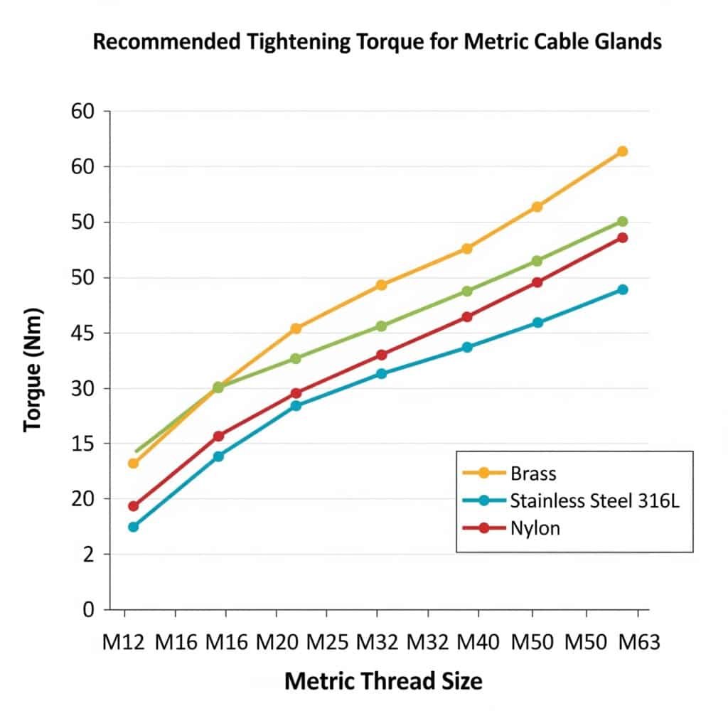
Metric Thread Cable Glands (Standard Applications)
Brass Cable Glands
- M12: 8-12 Nm
- M16: 12-18 Nm
- M20: 15-22 Nm
- M25: 18-28 Nm
- M32: 25-35 Nm
- M40: 30-42 Nm
- M50: 35-50 Nm
- M63: 40-60 Nm
Stainless Steel 316L Cable Glands
- M12: 10-15 Nm
- M16: 15-22 Nm
- M20: 18-28 Nm
- M25: 22-35 Nm
- M32: 30-45 Nm
- M40: 35-52 Nm
- M50: 42-58 Nm
- M63: 48-65 Nm
Nylon Cable Glands (UV-Stabilized)
- M12: 6-10 Nm
- M16: 8-14 Nm
- M20: 10-16 Nm
- M25: 12-20 Nm
- M32: 15-25 Nm
- M40: 18-30 Nm
- M50: 22-35 Nm
- M63: 25-40 Nm
NPT Thread Cable Glands
NPT threads3 require different torque values due to their tapered design:
Brass NPT Cable Glands
- 1/2″ NPT: 20-30 Nm
- 3/4″ NPT: 25-40 Nm
- 1″ NPT: 35-50 Nm
- 1-1/4″ NPT: 45-65 Nm
- 1-1/2″ NPT: 55-75 Nm
- 2″ NPT: 65-90 Nm
Specialized Application Adjustments
Explosion-Proof (ATEX/IECEx) Cable Glands
- Add 10-15% to standard values for enhanced sealing
- Maximum torque limits to prevent thread damage
- Mandatory torque documentation for certification compliance
EMC Cable Glands
- Reduce by 10% to prevent shield compression damage
- Focus on uniform compression around cable shield
- Special consideration for braided shield integrity
Marine Cable Glands
- Standard values apply with stainless steel materials
- Thread compound required for corrosion prevention
- Regular re-torque schedule due to thermal cycling
Real-World Application Example
Marcus from Manchester learned this lesson the hard way. His team was installing M25 brass cable glands and applying 50 Nm torque – nearly double our recommended maximum of 28 Nm. Result? Crushed O-rings, extruded seals, and water ingress within a week.
After switching to our recommended 22 Nm torque with proper technique, his follow-up installations have been leak-free for over two years. The key was using a calibrated torque wrench and following our step-by-step procedure.
How Do You Know When You’ve Over-Tightened a Cable Gland?
Recognition is the first step to prevention. Over-tightening symptoms are often visible during installation, but some only appear over time.
Over-tightening symptoms include visible seal extrusion, thread damage, stress whitening in plastic materials, and difficulty in future disassembly. Early recognition prevents installation failure and allows corrective action before system commissioning.
Immediate Visual Indicators
Seal Extrusion
- O-ring squeeze-out around threads or mating surfaces
- Gasket material visible outside intended grooves
- Uneven compression with material bunching on one side
Thread Damage
- Cross-threading or thread deformation
- Metal shavings from brass or aluminum glands
- Galling4 marks on stainless steel threads
Material Stress Signs
- Stress whitening in nylon materials around threads
- Micro-cracking in plastic components
- Surface deformation or tool marks
Performance-Based Indicators
Installation Resistance
- Sudden increase in turning resistance
- Grinding or scraping sounds during tightening
- Uneven torque progression (should be smooth and consistent)
Post-Installation Issues
- Inability to remove for maintenance
- Continued tightening without seal improvement
- Cable damage from excessive compression
Long-Term Failure Patterns
Environmental Seal Failure
Despite appearing tight, over-tightened glands often fail IP testing due to:
- Damaged seals that can’t maintain compression
- Stress concentration causing premature aging
- Uneven loading creating leak paths
Mechanical Degradation
- Thread wear accelerating with thermal cycling
- Stress cracking propagation over time
- Galvanic corrosion at damaged interfaces
The “Feel” Factor
Experienced installers develop a sense for proper torque, but it’s not reliable enough for critical applications. Here’s what proper installation should feel like:
- Initial threading: Smooth, even resistance
- Seal engagement: Gradual increase in torque requirement
- Final tightening: Steady resistance to target torque
- Completion: Clean stop at specified value
Sarah, a senior electrician from a wind farm in Texas, described it perfectly: “It should feel like you’re compressing something, not crushing it. When the torque wrench clicks, you should feel like you could go a little more, but you don’t need to.”
Correction Techniques
If you suspect over-tightening:
- Stop immediately – don’t continue tightening
- Back off 1/4 turn and reassess
- Check seal condition for damage
- Replace damaged components before proceeding
- Use proper torque values for reinstallation
What Tools and Techniques Ensure Perfect Torque Application?
The right tools make perfect torque application straightforward and repeatable. After testing dozens of options with our installation teams, I can recommend the most effective approaches.
Calibrated torque wrenches5 with appropriate socket sets provide the most reliable torque application, while proper technique ensures consistent results across different installers and conditions. The investment in quality tools pays for itself in reduced callbacks and improved reliability.
Essential Torque Tools
Torque Wrench Selection
Click-Type Torque Wrenches (Recommended)
- Range: 5-60 Nm covers most cable gland applications
- Accuracy: ±3% for professional models
- Durability: Mechanical mechanism, reliable in field conditions
- Cost: $150-400 for quality units
Digital Torque Wrenches (Premium Option)
- Features: Real-time display, data logging, multiple units
- Accuracy: ±2% with temperature compensation
- Benefits: Audit trail capability, preset values
- Cost: $300-800 for professional models
Beam-Type Torque Wrenches (Budget Option)
- Simplicity: No calibration drift, always accurate
- Limitations: Harder to read, requires good lighting
- Applications: Low-volume installations
- Cost: $50-150
Socket and Adapter Requirements
Standard Hex Sockets
- Sizes needed: 8mm, 10mm, 13mm, 17mm, 19mm, 22mm, 27mm, 32mm
- Quality: Chrome vanadium steel minimum
- Length: Short sockets for confined spaces
Specialized Cable Gland Tools
- Spanner wrenches: For glands with slots instead of hex
- Pin spanners: For adjustment rings on some designs
- Strap wrenches: For large diameter or round glands
Professional Installation Technique
Step-by-Step Torque Application
Preparation Phase
– Clean all threads and mating surfaces
– Apply thread sealant if specified
– Hand-tighten to finger-tight plus 1/2 turnInitial Torque Application
– Set torque wrench to 50% of target value
– Apply torque smoothly and steadily
– Check for proper seal engagemenFinal Torque Application
– Increase to full target torque
– Apply in smooth, continuous motion
– Stop immediately when wrench clicksVerification
– Back off 1/8 turn and re-torque to verify setting
– Check for seal extrusion or damage
– Document torque value applied
Common Technique Mistakes
Rapid or Jerky Application
- Causes uneven stress distribution
- Can damage threads or seals
- Results in inaccurate torque readings
Multiple Click Ignoring
- Continuing past the first click
- Over-torques and damages components
- Defeats the purpose of using a torque wrench
Wrong Angle Application
- Torque wrench not perpendicular to fastener
- Results in incorrect torque values
- Can damage the wrench mechanism
Quality Control and Documentation
Installation Records
For critical applications, maintain records including:
- Gland size and type
- Target torque specification
- Actual torque applied
- Installer identification
- Date and environmental conditions
Torque Wrench Maintenance
- Annual calibration for professional use
- Proper storage at lowest setting
- Regular inspection for damage or wear
- Replacement schedule based on usage volume
David from that Arizona solar project now requires all his installers to use calibrated torque wrenches and maintain installation logs. His callback rate dropped from 15% to less than 1% after implementing these procedures.
How Do Environmental Factors Affect Torque Requirements?
Environmental conditions significantly impact both the torque application process and long-term performance. Understanding these factors helps you adjust techniques for optimal results.
Temperature, humidity, vibration, and chemical exposure all affect optimal torque values and long-term joint integrity, requiring application adjustments of ±10-20% from standard specifications. Environmental compensation ensures reliable performance across varying conditions.
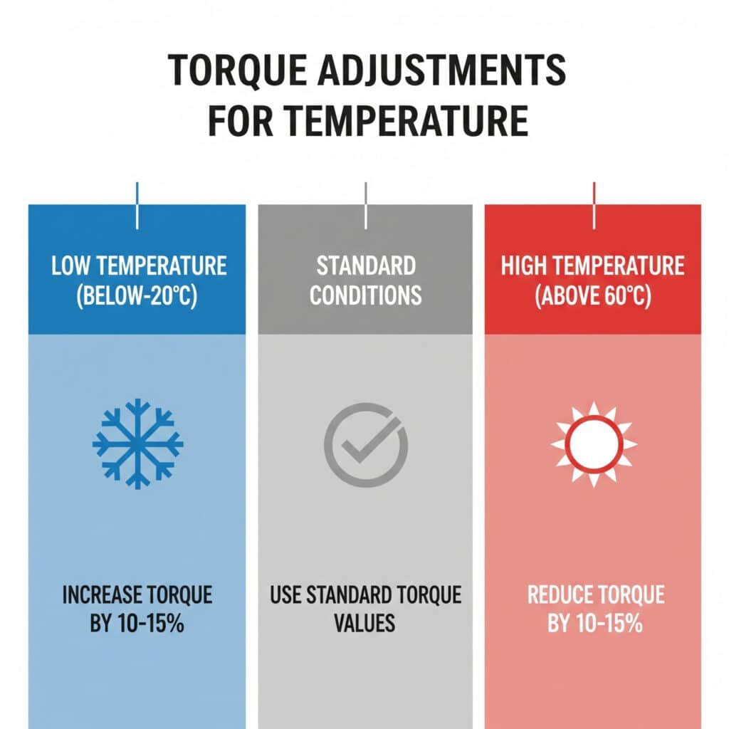
Temperature Effects
High Temperature Applications (Above 60°C)
- Reduce torque by 10-15% to account for thermal expansion
- Material softening reduces required compression force
- Seal expansion provides additional sealing pressure
- Re-torque schedule needed due to thermal cycling
Low Temperature Applications (Below -20°C)
- Increase torque by 10-15% to compensate for material hardening
- Seal stiffening requires higher compression force
- Thermal contraction reduces joint preload
- Cold weather lubricants may be required
Thermal Cycling Environments
- Standard torque values with scheduled re-torquing
- Quarterly inspections for joint integrity
- Spring washers or similar devices to maintain preload
- Material selection critical for coefficient of expansion matching
Vibration and Mechanical Stress
High Vibration Environments
Examples: Motor mounts, conveyor systems, mobile equipment
Adjustments Required:
- Increase torque by 15-20% for additional preload
- Thread locking compound application
- More frequent inspection schedule (monthly)
- Vibration-resistant seal materials
Shock and Impact Applications
Examples: Mining equipment, construction machinery
Special Considerations:
- Maximum torque values to prevent stress concentration
- Flexible mounting to absorb impact energy
- Redundant sealing systems where possible
- Regular replacement schedule regardless of appearance
Chemical Environment Adjustments
Corrosive Atmospheres
- Stainless steel materials mandatory
- Reduced torque values to prevent stress corrosion cracking
- Specialized thread compounds for corrosion resistance
- Accelerated inspection schedules
Hydrocarbon Exposure
- Chemical compatibility verification for all seal materials
- Standard torque values typically acceptable
- Explosion-proof requirements may override standard practices
- Specialized cleaning procedures for maintenance
Humidity and Moisture Considerations
High Humidity Environments (>80% RH)
- Corrosion prevention measures for metal components
- Drainage provisions for condensation management
- Seal material selection for moisture resistance
- Standard torque values with corrosion monitoring
Submersible Applications
- Maximum specified torque for optimal seal compression
- Hydrostatic pressure considerations for deep installations
- Specialized sealing compounds for underwater service
- Pressure testing verification before deployment
Real-World Environmental Case Study
Hassan’s petrochemical facility in Kuwait presents multiple environmental challenges:
- Temperature range: -5°C to 65°C
- Humidity: 20-95% RH
- Chemical exposure: H2S, hydrocarbons, salt spray
- Vibration: Pump and compressor installations
Our solution involved:
- Stainless steel 316L cable glands exclusively
- Torque values adjusted +15% for vibration, -10% for high temperature
- Quarterly re-torque schedule during maintenance shutdowns
- Specialized thread sealant for chemical resistance
Results: Zero environmental seal failures in three years of operation, compared to monthly failures with the previous standard approach.
Environmental Torque Adjustment Chart
| Condition | Torque Adjustment | Inspection Frequency | Special Requirements |
|---|---|---|---|
| High Temp (>60°C) | -10 to -15% | Quarterly | Thermal expansion joints |
| Low Temp (<-20°C) | +10 to +15% | Bi-annual | Cold-weather lubricants |
| High Vibration | +15 to +20% | Monthly | Thread locking compound |
| Corrosive Atmosphere | -5 to -10% | Monthly | Stainless steel materials |
| High Humidity | Standard | Quarterly | Corrosion monitoring |
| Submersible | Maximum spec | Before deployment | Pressure testing |
Conclusion
Perfect cable gland torque isn’t about following a single number – it’s about understanding the complete system and adapting to your specific conditions. The difference between a reliable installation and a costly callback often comes down to proper torque application and environmental consideration.
Remember Marcus’s expensive lesson in Manchester: over-tightening caused more problems than under-tightening ever could. The key is finding that sweet spot where seals compress properly without damage, threads engage correctly without galling, and long-term performance meets your reliability requirements.
At Bepto Connector, we provide detailed torque specifications with every shipment because we know that proper installation is just as important as quality manufacturing. Our technical support team is always available to help you navigate specific application challenges and ensure your installations perform flawlessly for years to come. 😉
FAQ
Q: What happens if I don’t use a torque wrench for cable gland installation?
A: Without a torque wrench, you risk over-tightening (causing seal damage) or under-tightening (allowing water ingress). Hand-tightening typically results in 2-5 times the optimal torque, leading to premature failure and costly repairs.
Q: Can I reuse a cable gland that was over-tightened?
A: It depends on the damage extent. If only the O-ring is extruded, replacement of seals may allow reuse. However, if threads are damaged or plastic components show stress cracking, the entire gland should be replaced for reliable performance.
Q: How often should I re-torque cable glands in outdoor installations?
A: For standard outdoor applications, annual re-torquing is sufficient. High-vibration or thermal cycling environments may require quarterly checks, while stable indoor installations rarely need re-torquing unless disturbed for maintenance.
Q: Why do nylon cable glands require lower torque values than metal ones?
A: Nylon has lower compressive strength and higher stress concentration sensitivity than metals. Excessive torque can cause stress cracking, thread stripping, or permanent deformation that compromises long-term sealing performance.
Q: What’s the best torque wrench range for general cable gland installation work?
A: A 5-60 Nm range torque wrench covers 95% of cable gland applications from M12 to M63 sizes. This range handles everything from small control panels to large industrial installations with a single tool.
-
Learn the fundamental engineering principle of torque and how it is measured. ↩
-
Review the official International Electrotechnical Commission standard that defines the Ingress Protection (IP) rating system. ↩
-
Explore the American National Standard Pipe Thread standard and how its tapered design creates a fluid-tight seal. ↩
-
Understand this form of wear caused by adhesion between sliding surfaces, a common issue when tightening threaded fasteners. ↩
-
Discover the different types of torque wrenches and the mechanisms they use to apply a precise amount of torque. ↩
