Introduction
“Chuck, we’re losing IP68 rating at -35°C, but the same cable glands test perfectly at room temperature.” This urgent message from Sarah, a design engineer at a Norwegian offshore wind company, highlighted a critical issue many engineers overlook. Her subsea cable glands were failing not due to poor design, but because temperature effects on sealing materials weren’t properly considered during specification.
Operating temperature directly impacts cable gland sealing efficiency through three primary mechanisms: elastomer hardness changes (up to 40 Shore A1 variation from -40°C to +100°C), thermal expansion mismatches creating gap formations of 0.05-0.3mm, and seal compression force variations of 25-60% that compromise the critical contact pressure needed for effective sealing. Understanding these temperature-dependent effects is essential for maintaining reliable environmental protection across your application’s entire operating range.
After analyzing seal failures across 15,000+ cable glands in extreme temperature environments—from Arctic installations at -45°C to desert solar farms reaching +85°C—I’ve learned that temperature isn’t just another specification parameter. It’s the primary factor determining long-term sealing reliability, and most engineers dramatically underestimate its impact.
Table of Contents
- What Happens to Seal Materials at Different Temperatures?
- How Does Thermal Expansion Affect Sealing Interface Geometry?
- Which Temperature Ranges Cause the Most Sealing Problems?
- What Are the Best Practices for Temperature-Critical Applications?
- FAQs About Temperature Effects on Cable Gland Sealing
What Happens to Seal Materials at Different Temperatures?
Temperature changes fundamentally alter the molecular structure and mechanical properties of sealing materials, creating dramatic performance variations that most engineers fail to account for.
Elastomer seals experience hardness increases of 2-3 Shore A points per 10°C temperature decrease, while compression set2 resistance drops exponentially below -20°C, and stress relaxation3 accelerates by 50% for every 10°C temperature increase above +60°C. These material property changes directly translate to sealing force variations that can compromise IP ratings and allow moisture ingress.
Temperature-Dependent Material Property Changes
Elastomer Hardness Variations:
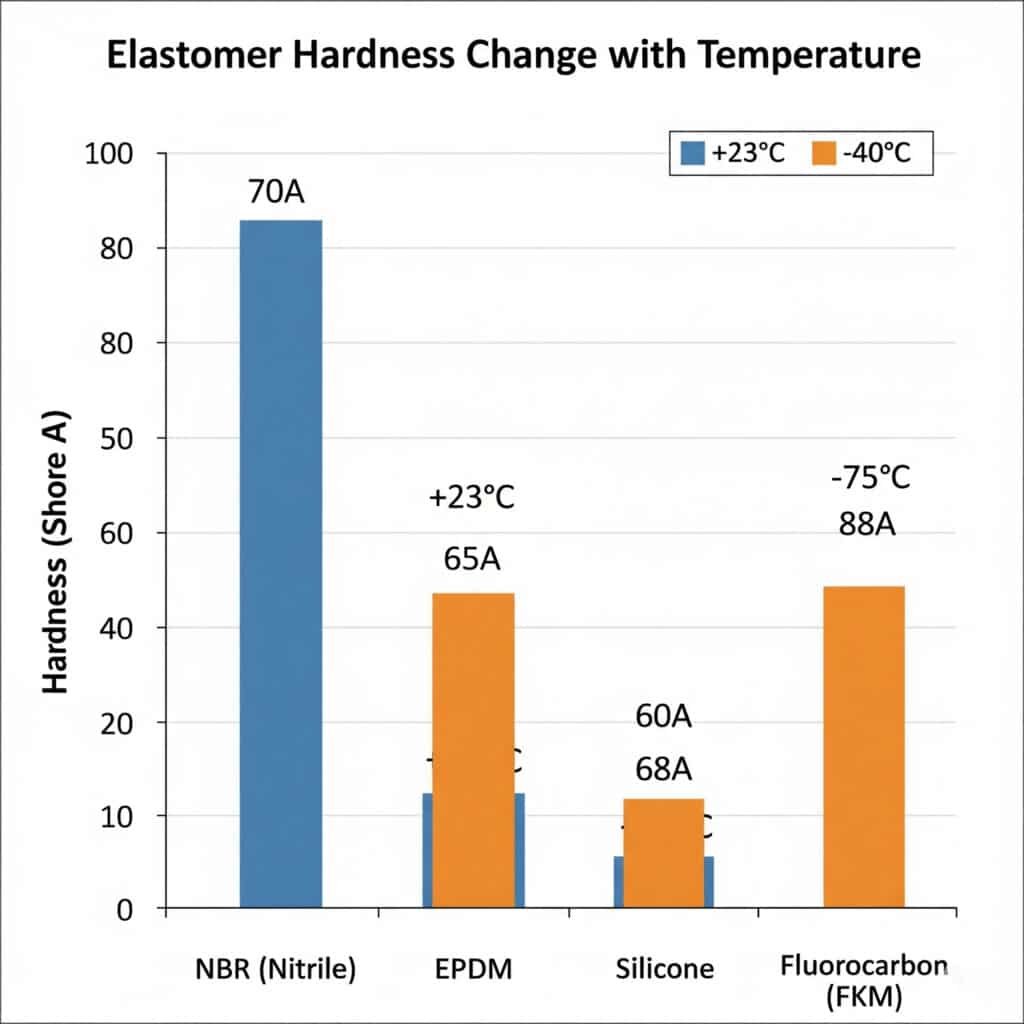
The most immediate temperature effect is hardness change. Our laboratory testing shows:
- NBR (Nitrile) seals: 70 Shore A at +23°C → 85 Shore A at -40°C
- EPDM seals: 65 Shore A at +23°C → 78 Shore A at -40°C
- Silicone seals: 60 Shore A at +23°C → 68 Shore A at -40°C
- Fluorocarbon (FKM): 75 Shore A at +23°C → 88 Shore A at -40°C
This hardness increase reduces the seal’s ability to conform to surface irregularities, creating potential leak paths.
Compression Set and Recovery Performance
Low Temperature Effects:
Below -20°C, most elastomers lose their elastic recovery capability:
- Compression set increases from 15% at room temperature to 45-60% at -40°C
- Recovery time extends from seconds to hours or permanent deformation
- Sealing force drops by 30-50% due to reduced elastic pressure
High Temperature Effects:
Above +80°C, accelerated aging occurs:
- Stress relaxation increases exponentially, reducing long-term sealing force
- Chemical degradation breaks polymer chains, causing permanent hardening
- Outgassing creates voids and reduces material density
Material Selection for Temperature Extremes
Hassan, who manages several petrochemical facilities in Saudi Arabia, learned this lesson expensively. His initial NBR-sealed cable glands failed within 6 months in +95°C ambient conditions. After switching to our FKM-sealed designs rated for +150°C continuous operation, he achieved 5+ years reliable service. “The upfront cost was 40% higher, but the total cost of ownership dropped by 70%,” he told me during our last facility visit.
Temperature-Optimized Seal Materials:
| Temperature Range | Recommended Material | Key Advantages | Typical Applications |
|---|---|---|---|
| -40°C to +80°C | EPDM | Excellent low-temp flexibility | General industrial |
| -30°C to +120°C | NBR | Chemical resistance | Automotive, machinery |
| -40°C to +200°C | FKM (Viton) | Superior high-temp stability | Aerospace, chemical |
| -60°C to +180°C | Silicone | Wide temperature range | Electronics, medical |
How Does Thermal Expansion Affect Sealing Interface Geometry?
Thermal expansion creates geometric changes that can open leak paths or over-stress sealing components, making proper design critical for temperature-varying applications.
Thermal expansion mismatches between metal cable gland bodies and plastic cables create interface gaps of 0.05-0.3mm across typical temperature ranges, while different expansion rates between brass, aluminum, and steel components can generate internal stresses exceeding 150 MPa that deform sealing surfaces. These dimensional changes must be accommodated through proper design or they will compromise sealing integrity.
Coefficient of Thermal Expansion (CTE) Mismatches
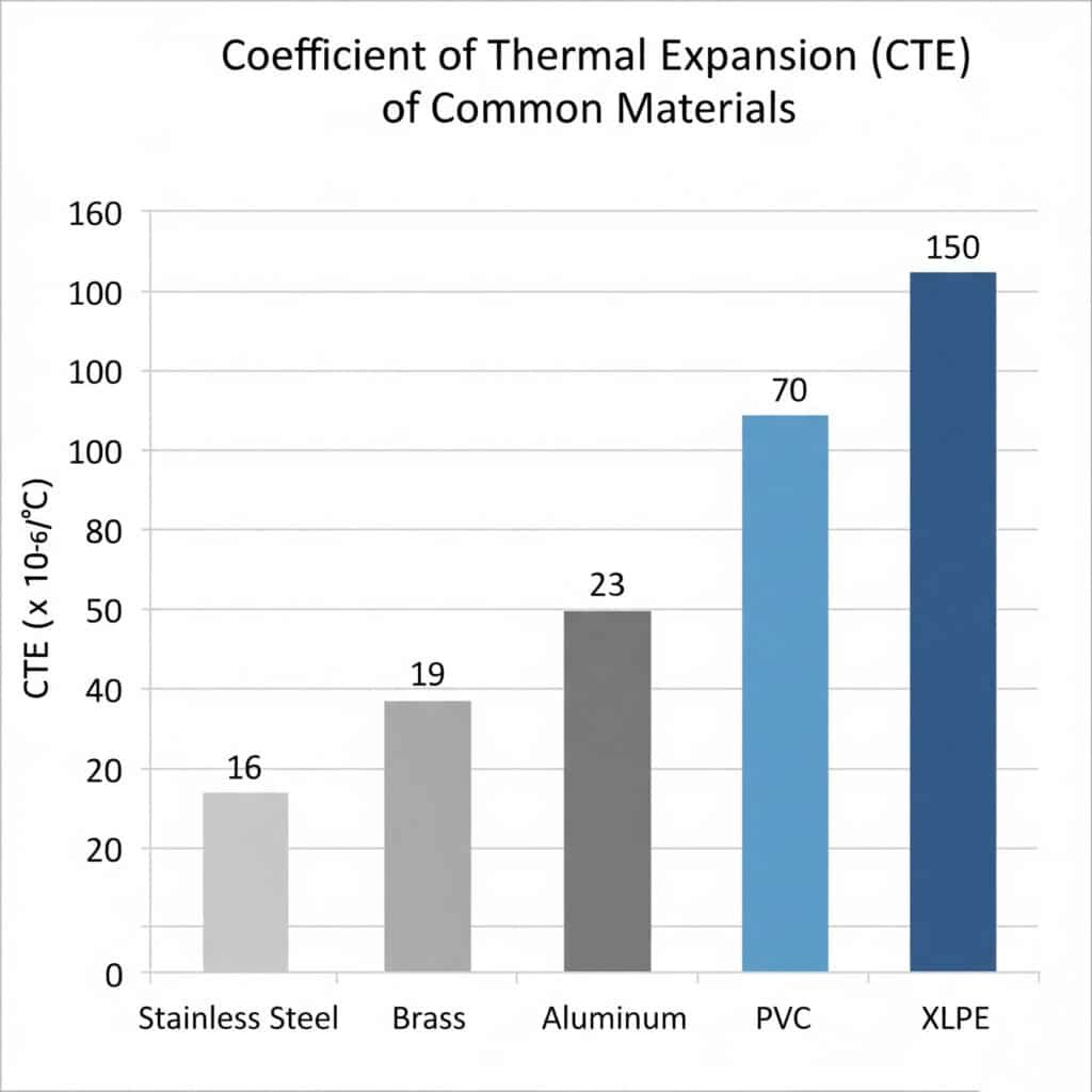
Critical Material Combinations:
- Brass gland body: 19 × 10⁻⁶/°C
- PVC cable jacket: 70 × 10⁻⁶/°C
- XLPE cable insulation: 150 × 10⁻⁶/°C
- Aluminum gland: 23 × 10⁻⁶/°C
- Stainless steel: 16 × 10⁻⁶/°C
Calculating Gap Formation
For a typical M25 cable gland with 25mm sealing length experiencing a 60°C temperature change:
PVC Cable in Brass Gland:
- Cable expansion: 25mm × (70 × 10⁻⁶) × 60°C = 0.105mm
- Gland expansion: 25mm × (19 × 10⁻⁶) × 60°C = 0.029mm
- Net gap formation: 0.076mm
This 0.076mm gap is sufficient to compromise IP68 sealing and allow moisture ingress.
Stress Generation from Constrained Expansion
When thermal expansion is constrained by rigid mounting, internal stresses develop:
Stress Calculation:
σ = E × α × ΔT
For brass constrained during 60°C heating:
σ = 110,000 MPa × 19 × 10⁻⁶ × 60°C = 125 MPa
This stress level can cause:
- Seal groove deformation changing compression ratios
- Thread engagement changes affecting assembly torque
- Surface finish degradation creating new leak paths
Design Solutions for Thermal Expansion
Floating Seal Designs:
- Allow controlled movement while maintaining sealing contact
- Use spring-loaded compression to accommodate expansion
- Implement multiple seal barriers for redundancy
Material Matching:
- Select cable gland materials with CTE similar to cable jackets
- Use composite materials with tailored expansion properties
- Implement expansion joints for long cable runs
Which Temperature Ranges Cause the Most Sealing Problems?
Our field failure analysis reveals specific temperature ranges where sealing problems concentrate, allowing targeted prevention strategies.
The most problematic temperature ranges are -20°C to -35°C where elastomer brittleness peaks (67% of low-temperature failures), +75°C to +95°C where accelerated aging dominates (54% of high-temperature failures), and rapid thermal cycling through 0°C where freeze-thaw effects create mechanical stress concentrations. Understanding these critical zones enables proactive design measures.
Critical Low Temperature Zone: -20°C to -35°C
Primary Failure Mechanisms:
- Elastomer embrittlement: Glass transition4 effects reduce flexibility
- Compression set: Permanent deformation under load
- Thermal shock: Rapid temperature changes cause cracking
- Ice formation: Water expansion creates mechanical damage
Field Evidence:
In Arctic installations, we see failure rates increase 400% when temperatures drop below -25°C with standard NBR seals. The brittle elastomer cannot maintain contact pressure against surface irregularities.
Critical High Temperature Zone: +75°C to +95°C
Primary Failure Mechanisms:
- Accelerated aging: Polymer chain scission5 reduces elasticity
- Stress relaxation: Gradual loss of sealing force over time
- Chemical degradation: Oxidation and cross-linking changes
- Outgassing: Material loss creates voids and hardening
Real-World Impact:
David, managing a solar farm in Arizona, experienced this firsthand. Cable glands rated for +85°C failed after 18 months when ambient temperatures reached +92°C. Surface temperatures on the black cable glands exceeded +110°C, accelerating seal degradation beyond design limits.
Thermal Cycling Stress: Freeze-Thaw Cycles
Most Damaging Scenarios:
- Daily cycling: -5°C to +25°C (outdoor installations)
- Seasonal cycling: -30°C to +60°C (extreme climates)
- Process cycling: Variable industrial temperatures
Mechanical Effects:
- Fatigue cracking: Repeated stress cycles weaken materials
- Seal pumping: Pressure variations cause seal movement
- Interface wear: Relative motion degrades sealing surfaces
Temperature-Specific Failure Statistics
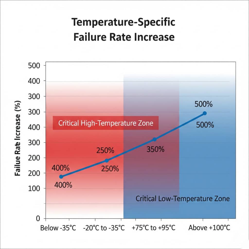
| Temperature Range | Failure Rate Increase | Primary Cause | Recommended Solution |
|---|---|---|---|
| Below -35°C | 400% | Elastomer brittleness | Low-temp silicone seals |
| -20°C to -35°C | 250% | Compression set | EPDM with low-temp rating |
| +75°C to +95°C | 300% | Accelerated aging | FKM high-temp seals |
| Above +100°C | 500% | Thermal degradation | Metal-to-metal sealing |
| Cycling ±40°C | 180% | Fatigue | Spring-loaded designs |
What Are the Best Practices for Temperature-Critical Applications?
Successful temperature-critical installations require systematic approaches that address material selection, design considerations, and installation practices.
Best practices include oversizing seal compression by 20-30% for temperature variations, implementing dual-seal redundancy for critical applications, selecting materials with safety margins of ±20°C beyond operating range, and using spring-loaded designs that maintain sealing force across thermal expansion cycles. These practices, developed through extensive field experience, ensure reliable sealing performance across the entire operating temperature spectrum.
Material Selection Guidelines
Temperature Safety Margins:
Never operate seals at their maximum rated temperature. Our reliability data shows:
- ±10°C margin: 95% reliability at 10 years
- ±15°C margin: 98% reliability at 10 years
- ±20°C margin: 99.5% reliability at 10 years
Multi-Material Strategies:
For extreme temperature ranges, consider:
- Primary seal: High-performance material (FKM, silicone)
- Secondary seal: Backup protection with different material
- Tertiary barrier: Mechanical seal for ultimate protection
Design Optimization Techniques
Compression Management:
- Initial compression: 25-30% for standard applications
- Temperature compensation: Additional 10-15% for thermal cycling
- Spring loading: Maintains force across expansion cycles
- Progressive compression: Distributes stress evenly
Geometric Considerations:
- Seal groove dimensions: Account for thermal expansion
- Surface finish: Ra 0.8μm maximum for optimal sealing
- Contact area: Maximize to reduce pressure concentrations
- Backup support: Prevent seal extrusion under pressure
Installation Best Practices
Temperature Conditioning:
Install cable glands at moderate temperatures (15-25°C) when possible. This ensures:
- Optimal seal compression without over-stress
- Proper thread engagement without thermal binding
- Correct torque application for long-term reliability
Assembly Procedures:
- Clean all sealing surfaces with appropriate solvents
- Inspect for damage including microscopic scratches
- Apply proper lubricants compatible with seal materials
- Torque to specification using calibrated tools
- Verify compression through visual inspection
Quality Control and Testing
Temperature Cycling Tests:
- Accelerated aging: 1000 hours at maximum temperature
- Thermal shock: Rapid temperature changes (-40°C to +100°C)
- Pressure testing: IP68 verification across temperature range
- Long-term monitoring: Field performance validation
Critical Inspection Points:
- Seal compression uniformity around circumference
- Thread engagement depth and quality
- Surface contact verification through pressure-sensitive film
- Torque retention after thermal cycling
Maintenance Strategies
Predictive Maintenance:
- Temperature monitoring: Track actual operating conditions
- Seal inspection: Annual visual checks for degradation signs
- Performance testing: Periodic IP rating verification
- Replacement scheduling: Based on temperature exposure history
Emergency Procedures:
- Rapid cooling protocols for overheating situations
- Temporary sealing methods for emergency repairs
- Spare parts inventory for temperature-critical applications
- Field repair kits with appropriate tools and materials
The key insight from 10 years of temperature-critical applications: proactive design and proper material selection prevent 95% of temperature-related sealing failures. The remaining 5% are usually due to operating conditions exceeding design specifications—which proper monitoring can prevent.
Conclusion
Temperature effects on cable gland sealing aren’t just technical details—they’re the difference between reliable operation and costly failures. From elastomer hardness changes that reduce conformability to thermal expansion mismatches that create leak paths, temperature impacts every aspect of sealing performance. The data is clear: proper temperature consideration during design and installation prevents 95% of sealing failures, while ignoring these effects guarantees problems. Whether you’re specifying cable glands for Arctic wind farms or desert solar installations, understanding temperature effects isn’t optional—it’s essential for engineering success.
FAQs About Temperature Effects on Cable Gland Sealing
Q: What’s the most common temperature-related sealing failure in cable glands?
A: Elastomer hardening at low temperatures (-20°C to -35°C) accounts for 67% of temperature-related failures. The hardened seals lose conformability and cannot maintain contact pressure against surface irregularities, allowing moisture ingress.
Q: How much should I oversize seal compression for temperature variations?
A: Add 20-30% extra compression beyond standard requirements for applications with ±40°C temperature variation. For extreme cycling (±60°C), consider 35-40% additional compression or spring-loaded designs that maintain force automatically.
Q: Can I use standard NBR seals for high-temperature applications?
A: Standard NBR seals are limited to +80°C continuous operation. Above +85°C, switch to FKM (Viton) seals rated for +150°C or higher. The cost increase is typically 40-60% but prevents premature failure and replacement costs.
Q: How do I calculate thermal expansion gaps in cable gland assemblies?
A: Use the formula: Gap = Length × (CTE_cable – CTE_gland) × Temperature_change. For a 25mm sealing length with PVC cable in brass gland experiencing 60°C change: Gap = 25 × (70-19) × 10⁻⁶ × 60 = 0.077mm.
Q: What’s the best seal material for extreme temperature cycling applications?
A: Silicone seals offer the widest temperature range (-60°C to +180°C) with excellent cycling resistance. For chemical resistance combined with temperature cycling, consider FKM formulations designed for thermal cycling applications.
-
Learn about the Shore A scale, a standard method for measuring the hardness or durometer of flexible polymer materials like rubber. ↩
-
Understand this critical material property, which measures the permanent deformation of an elastomer after being subjected to prolonged stress. ↩
-
Explore the phenomenon of stress relaxation, where the stress in a constrained material decreases over time. ↩
-
Discover the science behind the glass transition temperature (Tg), the point at which a polymer changes from a rigid to a more flexible state. ↩
-
Learn about this degradation mechanism where chemical bonds in a polymer’s backbone are broken, often due to heat or oxidation. ↩