

Introduction
Electrical installations fail catastrophically when the smallest components are overlooked, and nowhere is this more evident than with cable gland accessories. A missing locknut can cause vibration-induced loosening that leads to arcing1, fires, and equipment damage worth millions. Inadequate sealing washers allow moisture ingress that destroys sensitive electronics, while improperly installed earth tags create dangerous potential differences that can electrocute workers and damage equipment.
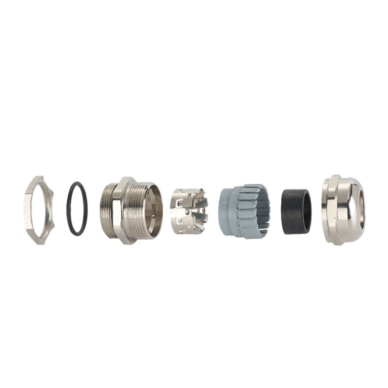
Cable gland accessories including locknuts, sealing washers, and earth tags are essential components that ensure mechanical security, environmental protection, and electrical safety in industrial installations, with each accessory serving specific functions that prevent common failure modes like vibration loosening, moisture ingress, and grounding faults that can cause catastrophic system failures.
Last year, David, procurement manager at a automotive manufacturing plant in Detroit, learned this lesson the hard way when 127 cable glands loosened due to missing locknuts, causing a production line shutdown that cost $1.8 million in lost production and emergency repairs. This comprehensive guide ensures you understand every critical accessory needed for reliable, long-term cable gland performance.
Table of Contents
- What Are the Essential Cable Gland Accessories and Their Functions?
- How Do Locknuts Prevent Mechanical Failure in Cable Gland Installations?
- Which Sealing Washers Provide Optimal Environmental Protection?
- Why Are Earth Tags Critical for Electrical Safety and EMC Compliance?
- How Do You Select and Install Cable Gland Accessories Correctly?
- FAQs About Cable Gland Accessories
What Are the Essential Cable Gland Accessories and Their Functions?
Understanding cable gland accessories isn’t just about completing an installation – it’s about preventing the most common failure modes that plague electrical systems worldwide.
Essential cable gland accessories include locknuts for mechanical retention, sealing washers for environmental protection, earth tags for electrical continuity, blanking plugs for unused entries, and shrouds for additional protection, each serving critical functions that standard cable glands cannot provide alone in demanding industrial environments.
Primary Accessory Categories
Mechanical Security Accessories:
- Locknuts: Prevent gland rotation and loosening under vibration
- Lock washers: Provide spring tension to maintain connection integrity
- Retaining clips: Secure accessories during installation and service
Environmental Protection Accessories:
- Sealing washers: Create weatherproof seals against panel surfaces
- Gaskets: Provide chemical-resistant sealing for harsh environments
- Shrouds: Offer additional protection from mechanical damage
Electrical Safety Accessories:
- Earth tags: Ensure proper grounding and EMC compliance
- Bonding straps: Provide low-impedance grounding paths
- Continuity washers: Maintain electrical connection through painted surfaces
Accessory Compatibility Matrix
Material Compatibility Requirements:
Different gland materials require specific accessory materials to prevent galvanic corrosion2:
| Gland Material | Compatible Locknut | Compatible Washer | Earth Tag Material |
|---|---|---|---|
| Nylon | Brass/Steel | EPDM/Neoprene | Brass/Stainless |
| Brass | Brass | Neoprene/Viton | Brass |
| Stainless Steel | Stainless Steel | Viton/PTFE | Stainless Steel |
| Aluminum | Aluminum/Steel | EPDM/Silicone | Aluminum/Steel |
Industry-Specific Requirements
Automotive Manufacturing (David’s Application):
David’s Detroit plant operates in a high-vibration environment with specific challenges:
- Vibration frequency: 10-500 Hz from production machinery
- Temperature cycling: -20°C to +80°C seasonal variations
- Contamination: Metal particles, cutting fluids, cleaning chemicals
- Required accessories: Lock washers, chemical-resistant sealing washers, stainless earth tags
Chemical Processing Applications:
- Corrosive environments: Require Viton or PTFE sealing materials
- Explosive atmospheres: Need ATEX-certified accessories with proper markings
- High temperatures: Demand specialized high-temperature sealing compounds
- Regulatory compliance: Must meet specific industry standards and certifications
Cost Impact Analysis
Accessory Cost vs. Failure Cost:
While accessories add 15-30% to initial gland cost, they prevent failures costing 1000x more:
David’s Automotive Plant Analysis:
- Standard gland cost: $12 per unit
- Required accessories: $4 per unit (locknut, sealing washer, earth tag)
- Total investment: $16 vs $12 (33% increase)
- Failure prevention value: $1.8M production loss avoided
- ROI calculation: 112,500% return on accessory investment
Failure Mode Prevention:
Each accessory prevents specific, costly failure modes:
- Missing locknuts: Vibration loosening, arcing, fire risk
- Inadequate sealing: Moisture ingress, corrosion, equipment failure
- Poor grounding: EMC issues, safety hazards, regulatory violations
- Incorrect materials: Galvanic corrosion, premature failure
At Bepto, we provide complete accessory kits matched to specific applications, ensuring compatibility and optimal performance while simplifying procurement and reducing the risk of missing critical components.
How Do Locknuts Prevent Mechanical Failure in Cable Gland Installations?
Locknuts are the unsung heroes of mechanical reliability, preventing vibration-induced failures that can shut down entire production facilities and create serious safety hazards.
Locknuts prevent cable gland mechanical failure by creating a positive mechanical lock against the mounting panel, distributing loads evenly, preventing rotation under vibration, and maintaining consistent compression on sealing elements through proper torque application and thread engagement in high-vibration industrial environments.
Locknut Design and Function
Thread Engagement Principles:
Proper locknut installation requires understanding thread mechanics:
- Minimum engagement: 1.5 times the thread pitch for reliable holding
- Maximum engagement: Limited by panel thickness and gland geometry
- Thread condition: Clean, undamaged threads essential for proper torque transfer
- Lubrication: Anti-seize compounds3 prevent galling in dissimilar metals
Load Distribution Mechanics:
Locknuts distribute installation stresses across the panel surface:
Stress Analysis:
- Point loading: Without locknut, all stress concentrates at gland shoulder
- Distributed loading: Locknut spreads load across larger panel area
- Vibration resistance: Locknut prevents micro-movement that causes loosening
- Fatigue prevention: Even load distribution prevents crack initiation
Material Selection Criteria
Standard Locknut Materials:
Brass Locknuts:
- Applications: General industrial, moderate corrosion environments
- Advantages: Good corrosion resistance, easy machining, cost-effective
- Limitations: Not suitable for high-temperature or marine applications
- Compatibility: Works with brass and nylon glands
Stainless Steel Locknuts:
- Applications: Food processing, marine, chemical, high-temperature
- Advantages: Excellent corrosion resistance, high strength, temperature stable
- Limitations: Higher cost, potential for galling with stainless glands
- Compatibility: Universal compatibility with proper anti-seize
Steel Locknuts (Zinc Plated):
- Applications: Indoor industrial, automotive, general manufacturing
- Advantages: High strength, low cost, readily available
- Limitations: Limited corrosion resistance, not suitable for outdoor use
- Compatibility: Good with nylon glands, requires coating compatibility check
Installation Best Practices
Torque Specifications:
David’s automotive plant developed specific torque procedures after their failure:
Torque Values by Size:
| Thread Size | Brass Locknut | Steel Locknut | Stainless Locknut |
|---|---|---|---|
| M12 | 8-12 Nm | 12-15 Nm | 10-14 Nm |
| M16 | 15-20 Nm | 20-25 Nm | 18-22 Nm |
| M20 | 25-30 Nm | 30-35 Nm | 28-32 Nm |
| M25 | 35-40 Nm | 40-45 Nm | 38-42 Nm |
| M32 | 45-50 Nm | 50-55 Nm | 48-52 Nm |
Installation Sequence:
- Panel preparation: Clean threads, check for damage, apply anti-seize if required
- Gland installation: Hand-tighten until gasket contacts panel surface
- Locknut positioning: Thread locknut until hand-tight against panel
- Final torquing: Apply specified torque to locknut, not gland body
- Verification: Check for proper compression and alignment
Vibration Analysis and Prevention
Vibration-Induced Failure Mechanisms:
Understanding how vibration causes locknut failure helps prevent problems:
Frequency Analysis:
- Low frequency (1-50 Hz): Causes gross movement, requires higher torque
- Medium frequency (50-200 Hz): Most damaging, causes micro-loosening
- High frequency (200+ Hz): Less problematic but can cause fatigue
David’s Vibration Solution:
After the $1.8M failure, David’s team implemented comprehensive vibration control:
- Vibration mapping: Identified high-risk installation locations
- Locknut upgrade: Switched to nylon-insert locknuts for critical applications
- Torque protocol: Established regular re-torquing schedule
- Monitoring system: Installed vibration sensors on critical panels
Advanced Locknut Technologies:
- Nylon-insert locknuts: Provide thread locking without liquid compounds
- Prevailing torque locknuts: Maintain tension through controlled deformation
- Spring washers: Add continuous tension to compensate for settling
- Thread-locking compounds: Chemical solutions for permanent installations
Maintenance and Inspection
Inspection Schedule:
Regular locknut inspection prevents catastrophic failures:
- Initial: 30 days after installation to check for settling
- Routine: Every 6 months in high-vibration environments
- Annual: Complete torque verification and visual inspection
- After events: Following any significant vibration or thermal cycling
Inspection Checklist:
- Visual inspection for cracks, corrosion, or deformation
- Torque verification using calibrated torque wrench
- Check for proper thread engagement and alignment
- Verify locknut material compatibility with environment
- Document any changes or anomalies for trend analysis
At Bepto, we provide detailed installation guides and torque specifications for all our locknut accessories, along with training support to ensure proper installation techniques that prevent the costly failures David experienced.
Which Sealing Washers Provide Optimal Environmental Protection?
Sealing washers are the primary defense against environmental contamination, and selecting the wrong material or design can lead to catastrophic moisture ingress and equipment failure.
Optimal sealing washers for cable gland environmental protection include EPDM for general weather resistance, Viton for chemical compatibility, silicone for extreme temperatures, and PTFE for universal chemical resistance, with proper selection based on temperature range, chemical exposure, compression set resistance, and long-term aging characteristics.
Sealing Washer Material Properties
EPDM (Ethylene Propylene Diene Monomer):
- Temperature range: -40°C to +120°C continuous service
- Chemical resistance: Excellent against water, steam, acids, alkalis
- Advantages: Cost-effective, good weather resistance, FDA grades available
- Limitations: Poor petroleum product resistance, limited high-temperature capability
- Applications: General industrial, water treatment, food processing
Viton (Fluoroelastomer):
- Temperature range: -20°C to +200°C continuous service
- Chemical resistance: Outstanding against fuels, oils, chemicals
- Advantages: Excellent chemical compatibility, high-temperature capability
- Limitations: Higher cost, poor steam resistance, limited low-temperature flexibility
- Applications: Chemical processing, automotive, aerospace
Silicone Rubber:
- Temperature range: -60°C to +200°C continuous service
- Chemical resistance: Good against water, limited chemical resistance
- Advantages: Excellent temperature range, flexibility retention, FDA approved
- Limitations: Poor tear resistance, petroleum product incompatibility
- Applications: Food processing, medical devices, extreme temperature environments
Environmental Challenge Analysis
Hassan’s Petrochemical Application:
Hassan, operations director at a refinery in Abu Dhabi, faced multiple environmental challenges:
Environmental Conditions:
- Temperature extremes: -5°C winter nights to +55°C summer days
- Chemical exposure: Hydrocarbon vapors, H2S, caustic cleaning solutions
- Weather conditions: Sand storms, high humidity, UV exposure
- Pressure cycling: Process upsets create pressure differentials
Sealing Washer Selection Process:
Hassan’s team developed a systematic approach:
- Chemical compatibility matrix: Tested materials against actual process chemicals
- Temperature cycling tests: Verified performance through seasonal variations
- Compression set testing: Ensured long-term sealing effectiveness
- Field trials: Installed test samples in representative locations
Performance Results:
| Material | Service Life | Failure Mode | Cost Factor |
|---|---|---|---|
| Standard EPDM | 6 months | Chemical degradation | 1.0x |
| Viton FKM | 24 months | UV degradation | 3.2x |
| PTFE/Viton composite | 36+ months | No failures observed | 4.8x |
Compression and Sealing Mechanics
Proper Compression Requirements:
Sealing washers must achieve optimal compression for effective sealing:
Compression Guidelines:
- Under-compression: <15% compression allows leakage paths
- Optimal compression: 15-25% compression provides reliable sealing
- Over-compression: >30% compression causes material extrusion and failure
Sealing Mechanism Analysis:
- Initial contact: Washer conforms to surface irregularities
- Compression phase: Material flows into micro-gaps and scratches
- Sealing phase: Compressed material creates continuous barrier
- Long-term performance: Material must resist compression set4
Installation Techniques
Surface Preparation Requirements:
Proper sealing requires attention to panel surface conditions:
Surface Finish Specifications:
- Roughness: Ra 1.6-3.2 μm (63-125 μin) for optimal sealing
- Flatness: Within 0.1mm across sealing diameter
- Cleanliness: Free from oil, dirt, paint, or corrosion
- Material: Compatible with washer material to prevent galvanic issues
Installation Procedure:
- Surface inspection: Verify cleanliness and condition
- Washer positioning: Center washer on gland shoulder
- Initial compression: Hand-tighten until washer contacts panel
- Final compression: Apply specified torque through locknut
- Verification: Check for uniform compression around circumference
Advanced Sealing Solutions
Composite Sealing Systems:
For extreme applications, composite washers provide superior performance:
PTFE/Elastomer Composites:
- Construction: PTFE face with elastomer backing
- Advantages: Chemical resistance of PTFE with sealing of elastomer
- Applications: Chemical processing, pharmaceutical, food processing
Metal-Clad Washers:
- Construction: Elastomer core with metal facing
- Advantages: High-pressure capability, temperature resistance
- Applications: High-pressure systems, extreme temperatures
Quality Control and Testing
Incoming Inspection Requirements:
Hassan’s refinery implemented comprehensive quality control:
Test Parameters:
- Durometer testing: Verify material hardness consistency
- Compression set testing: 22 hours at 70°C, 25% compression
- Chemical compatibility: Immersion testing in actual process fluids
- Temperature cycling: -20°C to +80°C for 100 cycles
Field Performance Monitoring:
- Leak detection: Regular inspection for moisture ingress
- Material condition: Visual inspection for cracking, hardening, or swelling
- Replacement scheduling: Proactive replacement based on service history
- Documentation: Detailed records for reliability improvement
At Bepto, we maintain extensive chemical compatibility databases and can provide custom sealing washer solutions for specific applications. Our quality control ensures consistent performance and long service life in demanding environments like Hassan’s refinery. 😉
Why Are Earth Tags Critical for Electrical Safety and EMC Compliance?
Earth tags provide essential electrical continuity and electromagnetic compatibility that can mean the difference between safe operation and catastrophic electrical faults in industrial installations.
Earth tags are critical for electrical safety and EMC compliance because they provide low-impedance grounding paths, ensure electrical continuity through cable armor and shields, prevent dangerous potential differences, enable proper fault current flow for protective device operation, and maintain electromagnetic shielding effectiveness required by modern industrial standards.
Electrical Safety Functions
Ground Fault Protection:
Earth tags enable proper operation of ground fault protection systems:
Fault Current Path Analysis:
- Normal operation: Earth tag provides parallel path for shield currents
- Ground fault condition: Low-impedance path allows sufficient fault current
- Protective device operation: Adequate fault current trips breakers/fuses
- Personnel safety: Prevents dangerous touch potentials during faults
Equipotential Bonding5:
Earth tags maintain equal potential between equipment:
- Potential difference elimination: Prevents voltage differences between equipment
- Arc flash prevention: Reduces energy available for arc formation
- Static charge dissipation: Provides path for static electricity discharge
- Lightning protection: Ensures proper surge current distribution
EMC Compliance Requirements
Electromagnetic Shielding:
Modern industrial environments demand strict EMC compliance:
Shield Continuity Requirements:
- 360-degree connection: Earth tags provide circumferential shield contact
- Low-impedance path: Maintains shield effectiveness at high frequencies
- Transfer impedance: Minimizes coupling between circuits
- Common mode rejection: Reduces noise pickup in sensitive circuits
Regulatory Standards:
- IEC 61000 series: International EMC standards
- FCC Part 15: US electromagnetic compatibility requirements
- EN 55011: European industrial EMC standards
- CISPR standards: International radio interference limits
Earth Tag Design and Materials
Construction Types:
Stamped Earth Tags:
- Material: Brass, stainless steel, or tinned copper
- Advantages: Low cost, readily available, good conductivity
- Limitations: Limited current capacity, potential corrosion issues
- Applications: General industrial, low-current applications
Braided Earth Tags:
- Material: Tinned copper braid with terminal lugs
- Advantages: High current capacity, flexible installation
- Limitations: Higher cost, requires proper termination
- Applications: High-current applications, flexible connections
Spring-Loaded Earth Tags:
- Material: Beryllium copper or stainless steel springs
- Advantages: Maintains contact pressure, accommodates thermal expansion
- Limitations: Complex design, higher cost
- Applications: High-vibration environments, thermal cycling
Installation and Connection Methods
Proper Installation Techniques:
Marcus, electrical supervisor at a steel mill in Birmingham, UK, developed comprehensive earth tag procedures:
Installation Sequence:
- Surface preparation: Remove paint, corrosion, or contamination from contact areas
- Tag positioning: Ensure proper contact with cable armor or shield
- Connection torque: Apply specified torque to maintain contact pressure
- Continuity verification: Test electrical continuity with low-resistance ohmmeter
- Documentation: Record installation details and test results
Connection Torque Specifications:
| Earth Tag Size | Brass Tag | Stainless Tag | Copper Braid |
|---|---|---|---|
| M6 | 3-4 Nm | 4-5 Nm | 2-3 Nm |
| M8 | 6-8 Nm | 8-10 Nm | 4-6 Nm |
| M10 | 10-12 Nm | 12-15 Nm | 8-10 Nm |
| M12 | 15-18 Nm | 18-22 Nm | 12-15 Nm |
Common Installation Errors
Marcus’s Steel Mill Lessons:
After experiencing EMC compliance failures, Marcus identified common mistakes:
Critical Installation Errors:
- Paint interference: Failing to remove paint from contact surfaces
- Inadequate torque: Under-torquing connections leading to high resistance
- Material incompatibility: Using dissimilar metals causing galvanic corrosion
- Missing connections: Forgetting earth tags on shielded cables
- Poor documentation: Inadequate records for compliance verification
Corrective Actions Implemented:
- Surface preparation protocol: Mandatory paint removal and cleaning
- Torque verification: Calibrated torque wrenches and documentation
- Material standardization: Single earth tag material for each application
- Installation checklists: Mandatory verification of earth tag installation
- Training program: Comprehensive electrician training on proper techniques
Testing and Verification
Continuity Testing Requirements:
Proper earth tag installation requires verification:
Test Equipment:
- Low-resistance ohmmeter: Capable of measuring milliohm resistance
- Test current: Minimum 10A DC for accurate low-resistance measurement
- Calibration: Annual calibration traceable to national standards
- Documentation: Detailed test records for compliance verification
Acceptance Criteria:
- Maximum resistance: <0.1 ohm for most industrial applications
- Consistency: Resistance values within 10% of similar connections
- Stability: Resistance must remain stable under vibration testing
- Environmental: Performance maintained through temperature cycling
Maintenance and Inspection
Inspection Schedule:
- Initial: 30 days after installation to verify settling
- Annual: Complete visual and electrical testing
- After maintenance: Following any work that might affect connections
- Compliance audits: As required by regulatory authorities
Inspection Checklist:
- Visual inspection for corrosion, damage, or loosening
- Electrical continuity testing with calibrated equipment
- Torque verification on accessible connections
- Documentation review and update
- Compliance verification against applicable standards
At Bepto, we provide earth tags designed for specific applications and can assist with proper installation techniques and compliance verification. Our technical team works with customers like Marcus to ensure electrical safety and EMC compliance in demanding industrial environments.
How Do You Select and Install Cable Gland Accessories Correctly?
Proper selection and installation of cable gland accessories requires systematic analysis of application requirements, environmental conditions, and performance criteria to ensure long-term reliability and compliance.
Correct cable gland accessory selection and installation involves analyzing environmental conditions, mechanical stresses, electrical requirements, and regulatory compliance needs, followed by proper material selection, installation sequencing, torque application, and verification testing to ensure optimal performance and prevent common failure modes.
Selection Methodology
Application Analysis Framework:
Systematic accessory selection prevents costly mistakes:
Environmental Assessment:
- Temperature range: Continuous and peak operating temperatures
- Chemical exposure: Process chemicals, cleaning agents, atmospheric contaminants
- Mechanical stress: Vibration frequency, amplitude, and duration
- Electrical requirements: Grounding needs, EMC compliance, safety standards
David’s Automotive Plant Selection Process:
After the $1.8M failure, David implemented comprehensive selection criteria:
Selection Matrix Development:
| Requirement | Standard Grade | Premium Grade | Critical Grade |
|---|---|---|---|
| Vibration resistance | Steel locknut | Nylon-insert locknut | Prevailing torque |
| Chemical resistance | EPDM washer | Viton washer | PTFE composite |
| Temperature rating | -20°C to +80°C | -40°C to +120°C | -60°C to +200°C |
| Electrical continuity | Standard earth tag | Tinned earth tag | Braided earth tag |
Material Compatibility Matrix
Galvanic Corrosion Prevention:
Proper material selection prevents electrochemical corrosion:
Compatibility Guidelines:
| Primary Material | Compatible Accessories | Avoid | Reason |
|---|---|---|---|
| Brass gland | Brass locknut, brass earth tag | Aluminum accessories | Galvanic corrosion |
| Stainless gland | Stainless accessories | Carbon steel | Corrosion acceleration |
| Nylon gland | Any metal accessories | None | Non-conductive base |
| Aluminum gland | Aluminum or stainless | Brass, copper | Galvanic series |
Chemical Compatibility Testing:
Hassan’s refinery developed comprehensive compatibility testing:
Test Protocol:
- Sample preparation: Obtain representative material samples
- Chemical exposure: Immerse in actual process chemicals
- Temperature cycling: Simulate operating temperature variations
- Mechanical testing: Verify strength retention after exposure
- Long-term aging: Extended exposure to accelerate aging effects
Installation Procedures
Pre-Installation Preparation:
Proper preparation prevents installation problems:
Panel Preparation:
- Hole size verification: Ensure proper thread engagement
- Surface condition: Clean, flat surface for sealing washer contact
- Thread inspection: Check for damage or contamination
- Material compatibility: Verify panel material compatibility
Tool Requirements:
- Calibrated torque wrench: Appropriate range for application
- Thread gauge: Verify thread pitch and condition
- Surface roughness gauge: Ensure proper sealing surface
- Continuity tester: Verify electrical connections
Step-by-Step Installation Guide
Installation Sequence:
Proper sequence ensures optimal performance:
Step 1: Panel Preparation
- Clean installation area thoroughly
- Verify hole size and thread condition
- Check panel thickness and material
- Apply anti-seize compound if required
Step 2: Sealing Washer Installation
- Select appropriate washer material
- Position washer on gland shoulder
- Ensure washer is properly centered
- Check for damage or contamination
Step 3: Gland Installation
- Thread gland through panel from equipment side
- Hand-tighten until washer contacts panel
- Verify proper alignment and positioning
- Check for adequate thread engagement
Step 4: Locknut Installation
- Thread locknut onto gland from outside
- Hand-tighten until contact with panel
- Apply specified torque using calibrated wrench
- Verify locknut is properly seated
Step 5: Earth Tag Installation
- Position earth tag for optimal contact
- Apply specified connection torque
- Verify electrical continuity
- Document connection resistance
Quality Control and Verification
Installation Verification:
Marcus’s steel mill developed comprehensive verification procedures:
Verification Checklist:
- Visual inspection of all components
- Torque verification with calibrated tools
- Electrical continuity testing
- Sealing effectiveness verification
- Documentation completion
Performance Testing:
- Vibration testing: Simulate operating conditions
- Thermal cycling: Verify performance through temperature range
- Leak testing: Confirm sealing effectiveness
- Electrical testing: Verify grounding and continuity
Common Installation Mistakes
Critical Errors to Avoid:
Torque-Related Errors:
- Under-torquing: Inadequate compression, potential loosening
- Over-torquing: Material damage, stress concentration
- Inconsistent torquing: Uneven load distribution
- Wrong sequence: Torquing gland instead of locknut
Material Selection Errors:
- Incompatible materials: Galvanic corrosion, chemical attack
- Inadequate ratings: Temperature or chemical exposure limits exceeded
- Wrong specifications: Incorrect size, thread pitch, or configuration
- Missing components: Forgetting critical accessories
Maintenance and Service
Preventive Maintenance Schedule:
- Initial inspection: 30 days after installation
- Regular inspection: Every 6 months in demanding environments
- Annual service: Complete disassembly and inspection
- Condition-based: Based on operating conditions and history
Service Procedures:
- Documentation review: Check installation and service history
- Visual inspection: Look for signs of deterioration or damage
- Electrical testing: Verify continuity and resistance values
- Replacement criteria: Establish clear replacement guidelines
Spare Parts Management:
- Critical spares: Maintain inventory of essential accessories
- Material traceability: Ensure compatibility with existing installations
- Quality control: Verify specifications and certifications
- Storage conditions: Proper storage to prevent deterioration
At Bepto, we provide complete installation guides, training materials, and technical support to ensure proper accessory selection and installation. Our field service team can assist with critical installations and provide ongoing support to prevent the costly failures experienced by customers like David and Marcus.
Conclusion
Cable gland accessories are far more than simple add-on components – they’re the critical elements that determine whether your electrical installation operates reliably for decades or fails catastrophically within months. From David’s $1.8 million automotive plant shutdown to Hassan’s petrochemical refinery challenges, the lessons are clear: proper accessory selection, installation, and maintenance are essential investments that pay for themselves many times over. Whether you need locknuts for vibration resistance, sealing washers for environmental protection, or earth tags for electrical safety, each accessory serves a vital function that cannot be overlooked. Remember, in industrial electrical installations, it’s often the smallest components that cause the biggest problems – and the biggest opportunities for improvement.
FAQs About Cable Gland Accessories
Q: What happens if I don’t use locknuts with my cable glands?
A: Without locknuts, cable glands will loosen under vibration, causing arcing, equipment damage, and potential fires. Locknuts provide essential mechanical retention that prevents rotation and maintains proper compression on sealing elements.
Q: Can I use any sealing washer material with my cable glands?
A: No, sealing washer material must be compatible with your specific application’s temperature, chemical exposure, and environmental conditions. EPDM works for general applications, but chemical environments require Viton or PTFE materials.
Q: How do I know if my earth tags are properly installed?
A: Proper earth tag installation requires electrical continuity testing with a low-resistance ohmmeter. Resistance should be less than 0.1 ohm, and connections must be torqued to specification with clean contact surfaces.
Q: What’s the difference between brass and stainless steel cable gland accessories?
A: Brass accessories offer good corrosion resistance and cost-effectiveness for general applications, while stainless steel provides superior corrosion resistance, higher strength, and better performance in marine, chemical, or high-temperature environments.
Q: How often should cable gland accessories be inspected and replaced?
A: Inspect accessories every 6 months in demanding environments, annually in standard applications. Replace based on visual condition, electrical testing results, and manufacturer recommendations – typically every 2-5 years depending on operating conditions.
-
Learn about the dangers of electrical arcing and arc flash events from an occupational safety resource. ↩
-
Understand how galvanic corrosion occurs between dissimilar metals and see a galvanic series chart. ↩
-
See a guide on the proper application of anti-seize compounds to prevent thread galling and corrosion. ↩
-
Get a technical explanation of compression set and how it is tested to determine long-term sealing performance. ↩
-
Explore the principle of equipotential bonding and its critical role in electrical safety and grounding. ↩
