

Overcrowded electrical panels and limited mounting space force engineers to compromise between cable management and system accessibility, leading to maintenance nightmares.
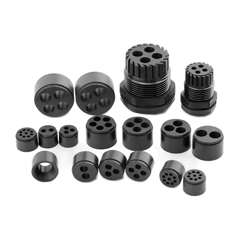
Multi-hole cable glands reduce panel space requirements by 60-80% while maintaining individual cable sealing and strain relief. They accommodate 2-12 cables per gland with IP68 protection and simplified installation procedures.
David’s control panel redesign project was failing until he discovered multi-hole glands could fit 8 cables in the space previously needed for 3 single-cable entries 😉.
Table of Contents
- What Are the Key Design Advantages of Multi-Hole Cable Glands Over Single-Cable Solutions?
- How Do You Select the Right Multi-Hole Configuration for Your Application?
- What Installation and Sealing Considerations Are Critical for Multi-Hole Performance?
- Which Applications Benefit Most from Multi-Hole Cable Gland Solutions?
What Are the Key Design Advantages of Multi-Hole Cable Glands Over Single-Cable Solutions?
Multi-hole cable glands revolutionize space utilization while maintaining the individual cable protection standards that engineers demand for critical applications.
Multi-hole designs provide 60-80% space savings, individual cable sealing, simplified installation, and reduced inventory requirements compared to single-cable glands. Each cable maintains independent strain relief and environmental protection.
Space Optimization Benefits
Panel Real Estate Efficiency
The most compelling advantage is dramatic space reduction:
Footprint Comparison Analysis
Our engineering team has documented significant space savings:
- 2-hole glands: 40% space reduction vs. dual single glands
- 4-hole configurations: 65% space savings with improved accessibility
- 6-hole designs: 75% reduction in required panel area
- 8+ hole systems: Up to 80% space optimization possible
Mounting Density Improvements
- Traditional approach: One M20 thread per cable
- Multi-hole solution: 4-8 cables per M32-M50 thread
- Panel utilization: Increased from 60% to 85% efficiency
- Access space: More room for maintenance and modifications
David’s compact control panel project achieved 70% space savings by replacing 24 individual M16 glands with 6 four-hole M32 units, creating room for additional I/O modules.
Design Flexibility Enhancement
Cable Routing Optimization
Multi-hole glands enable superior cable management:
Organized Cable Paths
- Parallel routing: Cables maintain organized parallel paths
- Separation capability: Different cable types in same gland
- Bend radius1 control: Consistent cable bend management
- Service loops: Easier maintenance access planning
Mixed Cable Applications
- Power and control: Separate holes for different cable types
- Signal segregation: EMI-sensitive cables isolated
- Future expansion: Unused holes for system growth
- Standardization: Consistent gland sizes across applications
Individual Cable Protection Integrity
Independent Sealing Systems
Each cable receives dedicated protection:
Per-Cable Sealing Technology
- Individual O-rings: Each cable has dedicated sealing elements
- Independent compression: Separate strain relief for each cable
- Isolated protection: Failure of one seal doesn’t affect others
- Maintenance access: Individual cable replacement without system shutdown
Environmental Protection Maintenance
- IP68 rating: Each cable entry maintains full environmental protection
- Chemical resistance: Individual sealing prevents cross-contamination
- Temperature stability: Independent thermal expansion accommodation
- Pressure resistance: Each seal handles full rated pressure
Hassan’s chemical plant uses our 6-hole stainless steel glands where each cable maintains IP68 sealing despite different cable diameters and materials in the same assembly.
Strain Relief Performance
Individual Cable Support
Each cable receives proper mechanical protection:
Load Distribution Analysis
- Independent clamping: Each cable has dedicated strain relief
- Load isolation: Cable movement doesn’t affect adjacent cables
- Fatigue prevention2: Individual support prevents cable stress
- Vibration dampening: Separate isolation for each cable
Cable Size Accommodation
- Mixed diameters: Different cable sizes in same gland
- Flexible sizing: Accommodate 6-20mm cables simultaneously
- Future changes: Easy cable replacement without gland modification
- Standardization: Common gland size for various cable types
Installation and Maintenance Advantages
Simplified Installation Process
Reduced Installation Time
Multi-hole glands streamline installation:
Time Efficiency Gains
- Single mounting: One gland replaces multiple installations
- Reduced drilling: Fewer panel penetrations required
- Simplified sealing: One primary seal vs. multiple gland seals
- Quality control: Fewer connection points to verify
Installation Error Reduction
- Consistent torque: Single tightening procedure
- Alignment simplification: One gland orientation vs. multiple
- Seal verification: Single primary seal to test
- Documentation: Simplified installation records
David’s installation team reduced panel wiring time by 40% using multi-hole glands, with 60% fewer potential leak points to test and verify.
Maintenance Accessibility
Service Efficiency Improvements
- Individual access: Service one cable without affecting others
- Reduced downtime: Partial system operation during maintenance
- Simplified troubleshooting: Easier cable identification and access
- Inventory reduction: Fewer gland types to stock
Long-term Serviceability
- Component replacement: Individual sealing elements replaceable
- System expansion: Add cables to unused holes
- Upgrade capability: Replace individual cables without system redesign
- Documentation: Simplified cable tracking and management
Cost-Effectiveness Analysis
Direct Cost Savings
Material Cost Reduction
- Fewer glands: Reduced unit count and inventory
- Simplified mounting: Fewer mounting hardware requirements
- Reduced labor: Installation time savings translate to cost savings
- Panel optimization: Smaller panels possible with space savings
Lifecycle Cost Benefits
- Maintenance efficiency: Reduced service time and complexity
- Inventory simplification: Fewer spare parts required
- System flexibility: Easier modifications and expansions
- Reliability improvement: Fewer connection points reduce failure modes
Hassan calculated 35% total cost reduction over 10 years by standardizing on multi-hole glands, including material, installation, and maintenance savings.
Indirect Value Creation
System Design Benefits
- Panel miniaturization: Smaller enclosures possible
- Improved aesthetics: Cleaner, more organized installations
- Enhanced safety: Better cable organization reduces hazards
- Future-proofing: Built-in expansion capability
Operational Advantages
- Faster troubleshooting: Organized cable routing improves diagnostics
- Reduced errors: Simplified installation reduces mistakes
- Improved documentation: Easier cable tracking and management
- Enhanced reliability: Fewer connection points improve system stability
How Do You Select the Right Multi-Hole Configuration for Your Application?
Proper multi-hole gland selection requires careful analysis of cable requirements, environmental conditions, and future expansion needs to optimize performance and cost.
Selection depends on cable count, diameter range, environmental protection requirements, and panel space constraints. Consider current needs plus 20-30% expansion capacity for future modifications and system growth.
Cable Requirements Analysis
Cable Count and Sizing Determination
Current and Future Cable Needs
Start with comprehensive cable analysis:
Cable Inventory Assessment
- Existing cables: Document all current cable requirements
- Planned additions: Include known future cable needs
- Expansion buffer: Add 20-30% capacity for unforeseen growth
- Cable replacement: Consider larger cables for future upgrades
Cable Diameter Compatibility
- Minimum size: Ensure smallest cables seal properly
- Maximum capacity: Verify largest cables fit comfortably
- Mixed sizing: Plan for different cable diameters simultaneously
- Standard sizes: Align with common cable specifications
David’s machine control panel analysis revealed 12 current cables (8-16mm) with plans for 4 additional control cables, leading to selection of dual 8-hole glands for optimal flexibility.
Cable Type Considerations
Electrical Compatibility
Different cable types may require separation:
Power vs. Control Separation
- EMI considerations: Separate power and signal cables
- Safety requirements: Isolate high and low voltage cables
- Code compliance: Meet electrical separation standards
- Interference prevention: Minimize crosstalk between cable types
Cable Construction Compatibility
- Armored cables: Require larger holes and special sealing
- Flexible cables: Need appropriate strain relief design
- Rigid cables: Require precise hole sizing
- Specialty cables: Fiber optic, coax, or instrumentation cables
Environmental and Performance Requirements
Protection Level Specifications
IP Rating Requirements
Match gland protection to application needs:
Environmental Exposure Assessment
- Water exposure: Splash, spray, or submersion requirements
- Dust protection: Clean room vs. industrial environment needs
- Chemical resistance: Process chemical compatibility requirements
- Temperature range: Operating temperature specifications
Performance Standards
- Pressure resistance: Wash-down or submersion pressure requirements
- Vibration tolerance: Equipment vibration and shock specifications
- UV resistance: Outdoor installation requirements
- Fire resistance: Safety and code compliance needs
Hassan’s offshore platform requires IP68 rating with saltwater resistance, leading to selection of marine-grade stainless steel multi-hole glands with specialized sealing compounds.
Material Selection Criteria
Housing Material Options
Choose materials based on environment:
Metal Housing Benefits
- Stainless steel: Superior corrosion resistance and strength
- Brass: Good conductivity and machinability
- Aluminum: Lightweight with adequate protection
- Zinc alloy: Cost-effective for moderate environments
Polymer Housing Advantages
- Nylon 66: Excellent chemical resistance and strength
- Polycarbonate: Impact resistance and transparency
- Modified polymers: Specialized chemical compatibility
- Cost effectiveness: Lower cost for suitable applications
Configuration Selection Guidelines
Hole Count Optimization
Capacity Planning Matrix
| Cable Count | Recommended Holes | Expansion Capacity | Typical Applications |
|---|---|---|---|
| 2-3 cables | 4-hole gland | 33-100% expansion | Small control panels |
| 4-6 cables | 6-8 hole gland | 33-100% expansion | Medium equipment |
| 6-10 cables | 8-12 hole gland | 20-100% expansion | Large control systems |
| 10+ cables | Multiple glands | Modular expansion | Complex installations |
Sizing Strategy Considerations
- Current utilization: Aim for 70-80% initial hole usage
- Future flexibility: Reserve holes for planned expansions
- Maintenance access: Ensure adequate space around each cable
- Cost optimization: Balance gland cost vs. expansion capability
Hole Size and Pattern Selection
Standard Hole Configurations
Common multi-hole patterns:
Symmetric Patterns
- 4-hole square: Equal spacing for uniform cables
- 6-hole circular: Optimal for round cable bundles
- 8-hole dual row: Linear arrangement for panel mounting
- 12-hole matrix: Maximum density for small cables
Custom Configurations
- Mixed hole sizes: Different diameter holes in same gland
- Asymmetric patterns: Optimized for specific cable layouts
- Specialty arrangements: Application-specific hole patterns
- Modular designs: Expandable configurations
David’s conveyor control system uses custom 6-hole glands with 4 standard holes (12mm) and 2 large holes (20mm) to accommodate mixed power and control cables efficiently.
Application-Specific Selection Criteria
Industry-Specific Requirements
Manufacturing Equipment
- Machine control: Multiple I/O and power cables
- Sensor networks: Numerous small signal cables
- Motor connections: Mixed power and feedback cables
- Safety systems: Dedicated emergency stop circuits
Process Industries
- Instrumentation: Multiple sensor and control cables
- Hazardous areas: Explosion-proof requirements
- Chemical exposure: Specialized material requirements
- Temperature extremes: High-temperature rated components
Infrastructure Applications
- Building automation: HVAC and lighting control cables
- Security systems: Camera and sensor networks
- Communication: Data and power cable combinations
- Renewable energy: Solar and wind power connections
Hassan’s refinery instrument panel consolidation project used explosion-proof multi-hole glands to reduce 48 individual penetrations to 8 multi-hole units while maintaining ATEX certification.
System Architecture Considerations
Panel Design Integration
- Space constraints: Available mounting area and depth
- Cable routing: Entry angle and bend radius requirements
- Maintenance access: Service clearance requirements
- Aesthetic requirements: Visual appearance and organization
Future Expansion Planning
- Technology upgrades: Anticipated cable technology changes
- System growth: Planned equipment additions
- Modification flexibility: Easy reconfiguration capability
- Standardization: Consistent gland types across systems
Selection Decision Framework
Evaluation Criteria Matrix
Technical Requirements Scoring
| Criteria | Weight | Score Method |
|---|---|---|
| Cable compatibility | 25% | Diameter range coverage |
| Environmental protection | 20% | IP rating and material suitability |
| Space efficiency | 20% | Panel space savings achieved |
| Future flexibility | 15% | Expansion capacity provided |
| Cost effectiveness | 10% | Total lifecycle cost analysis |
| Installation complexity | 10% | Installation time and difficulty |
Decision Support Tools
- Requirement checklists: Systematic evaluation of all factors
- Comparison matrices: Side-by-side option evaluation
- Cost-benefit analysis: Quantified value assessment
- Risk assessment: Identify potential issues and mitigation
Supplier Selection Considerations
Quality and Certification
- Manufacturing standards: ISO9001 and industry certifications
- Product testing: Third-party verification and testing
- Traceability: Material certificates and quality documentation
- Technical support: Engineering assistance and documentation
We at Bepto provide comprehensive selection guides and technical support to ensure optimal multi-hole gland selection for each unique application, backed by our ISO9001 quality system and extensive certification portfolio.
What Installation and Sealing Considerations Are Critical for Multi-Hole Performance?
Proper installation techniques and sealing procedures are essential for achieving rated performance and long-term reliability in multi-hole cable gland applications.
Critical factors include proper hole sizing, sequential cable installation, correct torque application, and individual seal verification. Each cable requires independent sealing validation to ensure system integrity and environmental protection.
Pre-Installation Planning and Preparation
Panel Preparation Requirements
Mounting Hole Specifications
Precise panel preparation ensures optimal performance:
Hole Sizing and Tolerance
- Diameter accuracy: ±0.1mm tolerance for proper thread engagement
- Edge finishing: Deburred edges prevent seal damage
- Panel thickness: Verify compatibility with gland thread length
- Mounting surface: Flat surface within 0.2mm for proper sealing
Thread Preparation
- Thread cutting: Use proper taps for clean thread formation
- Thread sealing: Apply appropriate thread sealant
- Torque specifications: Follow manufacturer torque requirements
- Quality verification: Check thread engagement before final installation
David’s installation team reduced seal failures by 90% after implementing strict panel preparation procedures, including proper hole sizing and edge finishing protocols.
Cable Preparation and Organization
Cable End Preparation
Proper cable preparation prevents installation issues:
Cable Stripping and Termination
- Strip length: Appropriate insulation removal for connections
- Conductor preparation: Clean, straight conductor ends
- Shield termination: Proper shield grounding where required
- Identification: Clear cable marking for future reference
Cable Routing Planning
- Entry angle: Plan cable approach angle to minimize stress
- Bend radius: Maintain manufacturer minimum bend radius
- Service loops: Provide adequate length for maintenance
- Cable support: Plan external cable support systems
Installation Procedure and Best Practices
Sequential Installation Process
Step-by-Step Installation Protocol
Follow systematic installation procedures:
Gland Body Installation
- Thread engagement: Hand-start threads to prevent cross-threading
- Sealing compound: Apply thread sealant as specified
- Torque application: Use calibrated torque wrench for proper tightening
- Seal verification: Check primary seal compression and alignment
Cable Installation Sequence
- Largest cables first: Install largest diameter cables initially
- Progressive sizing: Work down to smallest cables
- Individual sealing: Install and verify each cable seal
- Final adjustment: Check all cables for proper positioning
Hassan’s maintenance team developed a standardized 12-step installation procedure that reduced installation time by 30% while improving seal reliability to 99.8%.
Individual Cable Sealing Procedures
Per-Cable Sealing Verification
Each cable requires independent sealing validation:
Sealing Element Installation
- O-ring inspection: Check for damage before installation
- Lubrication: Use compatible lubricant for seal installation
- Compression verification: Ensure proper seal compression
- Position checking: Verify seal alignment and cable centering
Strain Relief Application
- Clamp positioning: Center cable in strain relief clamp
- Compression adjustment: Apply appropriate clamping force
- Cable protection: Verify no insulation damage from clamping
- Movement verification: Check cable cannot pull through
Sealing Performance Validation
Testing and Verification Procedures
Seal Integrity Testing
Comprehensive testing ensures reliable performance:
Pressure Testing Protocol
- Test pressure: Apply 1.5x rated pressure for verification
- Hold time: Maintain pressure for specified duration
- Leak detection: Use appropriate leak detection methods
- Documentation: Record test results for quality records
Environmental Testing
- Water ingress: Spray or submersion testing as appropriate
- Temperature cycling: Verify seal performance across temperature range
- Chemical exposure: Test with relevant process chemicals
- Vibration testing: Verify seal integrity under dynamic conditions
David’s quality control program includes 100% pressure testing of multi-hole installations, achieving zero field failures in over 500 installations.
Long-term Performance Monitoring
Preventive Maintenance Scheduling
- Inspection frequency: Regular visual and performance checks
- Seal replacement: Scheduled replacement based on service conditions
- Performance trending: Monitor seal performance over time
- Predictive maintenance: Identify potential issues before failure
Performance Indicators
- Visual inspection: Check for obvious damage or deterioration
- Pressure testing: Periodic re-testing of seal integrity
- Environmental monitoring: Track exposure conditions
- Performance documentation: Maintain detailed service records
Common Installation Issues and Solutions
Installation Error Prevention
Typical Installation Mistakes
Learn from common installation errors:
Improper Cable Sizing
- Problem: Cables too small or large for hole size
- Solution: Verify cable diameter compatibility before installation
- Prevention: Use cable sizing guides and verification tools
- Correction: Replace with properly sized gland or cables
Inadequate Seal Compression
- Problem: Insufficient or excessive seal compression
- Solution: Follow torque specifications and compression guidelines
- Prevention: Use calibrated tools and proper procedures
- Correction: Re-install with correct compression
Hassan’s installation audit revealed that 80% of seal failures resulted from improper torque application, leading to implementation of mandatory torque wrench calibration and training programs.
Troubleshooting Common Problems
Seal Failure Diagnosis
Systematic approach to seal problems:
Water Ingress Issues
- Symptom: Moisture inside enclosure
- Causes: Damaged seals, improper installation, or material incompatibility
- Diagnosis: Pressure testing and visual inspection
- Resolution: Seal replacement or installation correction
Cable Pull-out Problems
- Symptom: Cables move or pull through gland
- Causes: Insufficient strain relief or improper cable clamping
- Diagnosis: Pull testing and strain relief inspection
- Resolution: Proper strain relief adjustment or gland replacement
Quality Assurance and Documentation
Installation Quality Control
Quality Checkpoints
Implement systematic quality verification:
Installation Verification Checklist
- Panel preparation: Hole size, finish, and cleanliness
- Thread engagement: Proper thread sealing and torque
- Cable preparation: Proper stripping and identification
- Seal installation: Individual seal verification and testing
- Final testing: Complete system pressure and function testing
Documentation Requirements
- Installation records: Detailed installation documentation
- Test results: Pressure testing and verification results
- Material certificates: Seal and gland material certifications
- Maintenance schedules: Planned maintenance and inspection intervals
Certification and Compliance
Regulatory Compliance
Ensure installation meets all applicable standards:
Industry Standards
- IP rating verification: Confirm achieved protection level
- Safety certifications: Verify compliance with safety standards
- Environmental ratings: Confirm chemical and temperature compatibility
- Installation codes: Meet electrical and mechanical installation codes
We at Bepto provide comprehensive installation guides, training materials, and technical support to ensure proper multi-hole gland installation and optimal long-term performance 😉.
Which Applications Benefit Most from Multi-Hole Cable Gland Solutions?
Multi-hole cable glands excel in applications requiring high cable density, space optimization, and organized cable management while maintaining individual cable protection standards.
Control panels, instrumentation systems, machine automation, and compact equipment installations achieve maximum benefit. Applications with 4+ cables in limited space see 60-80% space savings with improved maintenance access and system organization.
Industrial Control and Automation Systems
Control Panel Applications
Machine Control Centers
Multi-hole glands transform control panel design:
Compact Control Solutions
- CNC machine controls: Multiple axis feedback and power cables
- Packaging equipment: Sensor networks and actuator controls
- Assembly line controls: Distributed I/O and communication cables
- Robotic systems: Power, control, and safety circuit consolidation
Space Optimization Benefits
- Panel miniaturization: 40-60% reduction in panel size possible
- Component density: More room for additional control components
- Cooling efficiency: Better airflow with organized cable routing
- Maintenance access: Improved technician access to components
David’s packaging line control panel redesign used 8-hole glands to consolidate 32 individual cable entries into 4 multi-hole units, reducing panel size by 50% while improving cable organization.
Process Control and Instrumentation
Distributed Control Systems
Multi-hole solutions excel in process applications:
Instrumentation Panels
- Sensor consolidation: Multiple temperature, pressure, and flow sensors
- Analyzer connections: Chromatograph and spectrometer cables
- Control valve networks: Positioner and feedback cables
- Safety system integration: Emergency shutdown and fire safety circuits
Field Junction Boxes
- Signal distribution: Multiple instrument signal cables
- Power distribution: 24VDC and 120VAC supply circuits
- Communication networks: Fieldbus and Ethernet connections
- Calibration access: Individual instrument isolation capability
Hassan’s chemical plant instrument consolidation project used explosion-proof multi-hole glands to reduce field junction box count by 60% while maintaining ATEX certification and individual circuit isolation.
Manufacturing and Production Equipment
Machine Tool Applications
CNC and Automated Machinery
Multi-hole glands optimize machine connectivity:
Spindle and Axis Control
- Servo motor connections: Power and encoder feedback cables
- Coolant system controls: Pump and valve control circuits
- Tool changer systems: Pneumatic and electrical controls
- Safety circuit integration: Light curtains and emergency stops
Production Line Integration
- Conveyor controls: Motor and sensor networks
- Quality inspection: Vision system and measurement cables
- Material handling: Pneumatic and electrical actuator controls
- Process monitoring: Temperature and vibration sensors
Packaging and Food Processing
Sanitary Design Requirements
Multi-hole glands meet hygiene standards:
Washdown Environment Solutions
- Stainless steel construction: Corrosion resistance for cleaning chemicals
- Smooth surfaces: Easy cleaning and sanitization
- IP69K rating3: High-pressure, high-temperature washdown capability
- FDA compliance: Food-grade materials and certifications
Equipment Integration
- Filling machines: Multiple valve and sensor controls
- Labeling systems: Print head and applicator controls
- Inspection systems: X-ray and metal detector connections
- Packaging equipment: Sealing and cutting mechanism controls
David’s food processing equipment uses IP69K rated multi-hole glands that withstand daily high-pressure sanitization while maintaining individual cable sealing for 24 control circuits.
Infrastructure and Building Systems
Building Automation Applications
HVAC Control Systems
Multi-hole glands simplify building system installation:
Centralized Control Integration
- Zone control panels: Multiple damper and sensor controls
- Equipment monitoring: Fan, pump, and compressor status circuits
- Energy management: Power monitoring and control circuits
- Safety integration: Fire damper and smoke detector circuits
Lighting Control Systems
- Dimming controls: Multiple lighting circuit controls
- Occupancy sensing: PIR and daylight sensor networks
- Emergency lighting: Battery backup and monitoring circuits
- Smart building integration: Communication and control networks
Security and Access Control
Integrated Security Systems
Multi-hole solutions enhance security installations:
Camera and Sensor Networks
- IP camera power: PoE and separate power circuits
- Access control: Card reader and lock control circuits
- Intrusion detection: PIR and door/window sensor circuits
- Communication networks: Ethernet and fiber optic connections
Perimeter Security
- Fence line detection: Vibration and cut detection sensors
- Lighting integration: Security lighting and control circuits
- Communication systems: Intercom and emergency call circuits
- Power distribution: UPS and backup power circuits
Hassan’s facility security upgrade consolidated 156 individual cable entries into 24 multi-hole glands, reducing installation time by 40% while improving cable organization and maintenance access.
Transportation and Mobile Applications
Railway and Transit Systems
Rolling Stock Applications
Multi-hole glands serve mobile equipment:
Train Control Systems
- Propulsion controls: Traction motor and control circuits
- Brake systems: Pneumatic and electrical brake controls
- Passenger systems: HVAC, lighting, and information displays
- Communication systems: Radio and passenger announcement circuits
Infrastructure Integration
- Signal systems: Track circuit and signal control cables
- Platform systems: Lighting and information display circuits
- Power distribution: Traction power and auxiliary circuits
- Safety systems: Emergency communication and detection circuits
Marine and Offshore Applications
Vessel Control Systems
Multi-hole glands excel in marine environments:
Engine Room Applications
- Propulsion controls: Engine management and monitoring circuits
- Auxiliary systems: Generator and pump control circuits
- Safety systems: Fire detection and suppression circuits
- Navigation integration: Radar and GPS system connections
Offshore Platform Integration
- Process control: Oil and gas processing equipment controls
- Safety systems: Emergency shutdown and fire protection circuits
- Communication systems: Radio and satellite communication circuits
- Power distribution: Generator and distribution control circuits
Renewable Energy Applications
Solar Power Systems
Photovoltaic Installations
Multi-hole glands optimize solar installations:
Array Connection Systems
- DC combiner boxes: Multiple string connections
- Inverter connections: DC input and AC output circuits
- Monitoring systems: Performance monitoring and communication circuits
- Safety systems: Rapid shutdown and arc fault detection circuits
Grid Integration
- Utility interconnection: Metering and protection circuits
- Energy storage: Battery management and control circuits
- Load management: Smart grid communication circuits
- Backup systems: Emergency power and transfer circuits
David’s 2MW solar installation used multi-hole glands in combiner boxes to reduce installation time by 35% while improving cable organization and maintenance accessibility.
Wind Power Applications
Turbine Control Systems
Multi-hole solutions serve wind applications:
Nacelle Integration
- Generator controls: Power and control circuits
- Pitch control: Blade angle control systems
- Yaw systems: Turbine orientation controls
- Safety systems: Lightning protection and emergency circuits
Tower and Foundation
- Power transmission: Generator output circuits
- Control systems: Turbine control and monitoring circuits
- Communication: SCADA4 and remote monitoring circuits
- Safety integration: Obstruction lighting and warning systems
Application Selection Guidelines
Optimal Use Case Identification
Primary Benefit Applications
Multi-hole glands provide maximum value when:
High Cable Density Requirements
- 4+ cables: Minimum cable count for space savings
- Limited panel space: Space constraints drive selection
- Organized routing: Cable management requirements
- Future expansion: Planned system growth
Cost-Benefit Analysis
- Installation savings: Reduced labor and material costs
- Space premiums: High-value panel real estate
- Maintenance efficiency: Improved service accessibility
- System reliability: Reduced connection points
Hassan’s application analysis showed multi-hole glands provide optimal value in applications with 6+ cables in space-constrained installations, delivering 45% total cost savings over traditional single-cable solutions.
Conclusion
Multi-hole cable glands maximize space efficiency and simplify installation while maintaining individual cable protection, making them ideal for high-density control and automation applications.
FAQs About Multi-Hole Cable Glands
Q: How many cables can a single multi-hole gland accommodate?
A: Multi-hole glands typically accommodate 2-12 cables depending on size and configuration. Common options include 4, 6, 8, and 12-hole designs with cable diameters from 3-25mm per hole.
Q: Do multi-hole glands maintain the same IP rating as single-cable glands?
A: Yes, properly installed multi-hole glands maintain full IP68 rating with each cable receiving individual sealing protection. Each hole has dedicated sealing elements for independent environmental protection.
Q: Can I mix different cable sizes in the same multi-hole gland?
A: Yes, most multi-hole glands accommodate mixed cable diameters within their specified range. Each hole can be sealed for different cable sizes using appropriate sealing inserts or gaskets.
Q: What happens if I don’t use all the holes in a multi-hole gland?
A: Unused holes must be sealed with blanking plugs to maintain the gland’s IP rating. These plugs provide the same environmental protection as cable-sealed holes.
Q: Are multi-hole glands more difficult to install than single-cable glands?
A: Installation is actually simpler overall despite initial complexity. While individual cable sealing requires attention, the reduced number of panel penetrations and single mounting procedure typically reduces total installation time by 30-40%.
-
Understand how to determine the minimum bend radius for different cable types and why exceeding it causes damage. ↩
-
Explore the concept of material fatigue and how cyclic loading leads to structural failure in components. ↩
-
See a detailed comparison of the IP69K and IP68 ratings and learn about the high-pressure washdown testing involved. ↩
-
Get an introduction to Supervisory Control and Data Acquisition (SCADA) systems and their role in industrial automation. ↩
